Philips Research Technical Note PR-TN-2003/00399
Issued: 06/2003
Specifications for the RGE Security Architecture A case study for a novel security modeling methodology
Joosten, H.J.M. (TNO Telecom) Knobbe, J.W. (TNO Telecom) Lenoir, P.J. Schaafsma, H. (TNO FEL) Kleinhuis, G. (TNO Telecom) (NATUURKUNDIG LABORATORIUM)
Unclassified Koninklijke Philips Electronics N.V. 2003
PR-TN-2003/00399
Authors’ address
Unclassified
Joosten, H.J.M. (TNO Telecom)
[email protected]
Knobbe, J.W. (TNO Telecom)
[email protected]
Lenoir, P.J.
WY 71
[email protected]
Schaafsma, H. (TNO FEL)
[email protected]
Kleinhuis, G. (TNO Telecom)
[email protected]
© KONINKLIJKE PHILIPS ELECTRONICS NV 2003 All rights reserved. Reproduction or dissemination in whole or in part is prohibited without the prior written consent of the copyright holder .
ii
Koninklijke Philips Electronics N.V. 2003
Unclassified
Koninklijke Philips Electronics N.V. 2003
PR-TN-2003/00399
iii
Unclassified
Title:
PR-TN-2003/00399
Specifications for the RGE Security Architecture A case study for a novel security modeling methodology
Author(s):
Joosten, H.J.M. (TNO Telecom); Knobbe, J.W. (TNO Telecom); Lenoir, P.J.; Schaafsma, H. (TNO FEL); Kleinhuis, G. (TNO Telecom)
Reviewers(s):
IPS Facilities
Technical Note:
PR-TN-2003/00399
Additional Numbers: Subcategory: Project:
DRM@HOME and on the Move (2002-060)
Customer:
Keywords:
formal specification, telecommunication security, security architecture, DRM, residential gateways
Abstract:
Within the Residential Gateway Environment (RGE) project (TS1021, together with TNO Telecom, TUe and TUD) research is performed on aspects of residential gateways and home enviroments, like (home)networking, remote/local storage, network access control, authorized domains and userinterfacing. Part of this research is the specification of the security architecture for the RGE. In this document a new specification and modeling methodology is used to specify the requirements of several security aspects related to residential gateways and home DRM systems (Authorized Domains). The used methodology is the Calculating with Concepts (CC) method. This method allows for a flexible definition of the concepts that are taken into account and which are grouped into directed graphs. The underlying mathematical model allows for the expression of restrictions on the relations between the concepts. These restrictions formally specify the behaviour of the model, but can also be easily expressed in normal written language. The mathematical model also allows for consistency checks on the restrictions across different, but related models. Such consistency checks ensure the correct use of concepts across different models, which therefore helps to increase the security of larger systems, as it can be better verified now that the same functionality in different subsystems behaves the same. This document has been published within the project as 'RGE D5.2'
Koninklijke Philips Electronics N.V. 2003
v
PR-TN-2003/00399
Unclassified
Contents Management Summary...................................................................................................9 List of Abbreviations .....................................................................................................10 1.
Introduction ............................................................................................................13 1.1. 1.2. 1.3. 1.4.
2.
Controlling Complexity, Interconnectedness, and Change.............................14 Controlling the Semantics of Words ...............................................................15 Formalism for Verifiable Consensus ..............................................................16 RGE Security Architecture .............................................................................17
Frames of Reference...............................................................................................18 2.1. Generic Network Services ..............................................................................18 2.1.1. Networks .............................................................................................18 2.1.2. Applications ........................................................................................23 2.1.3. Service Provisioning ...........................................................................26 2.1.4. Integrated Network Services ...............................................................28 2.2. Generic Content and Data ...............................................................................32 2.2.1. Content, Information, Data and Rights ...............................................32 2.2.2. Information, Data Users and Equipment.............................................35 2.2.3. Integrated model..................................................................................37 2.3. Generic Security..............................................................................................39 2.3.1. Registration .........................................................................................39 2.3.2. Authentication .....................................................................................41 2.3.3. Authorization.......................................................................................43 2.3.4. Contracts..............................................................................................46 2.3.5. Role-Based Access Control (RBAC) ..................................................48 2.3.6. Privacy 51 2.3.7. Integrated model..................................................................................52
3.
RGE specific Discussions .......................................................................................54 3.1. RGE Specific Models......................................................................................54 3.1.1. Applications within an RGE ...............................................................54 3.1.2. Packagers, Service Providers, and Services ........................................57 3.1.3. Services and Service Properties ..........................................................61 3.2. Authorized Domains .......................................................................................64
vi
Koninklijke Philips Electronics N.V. 2003
Unclassified
3.2.1. 3.2.2. 3.2.3. 3.2.4.
PR-TN-2003/00399
Domain Management ..........................................................................64 Content Rights provisioning................................................................68 Content Rights processing...................................................................71 Integrated Authorized Domain model.................................................74
4.
Conclusion ...............................................................................................................78
5.
References ...............................................................................................................80 5.1. List of URLs....................................................................................................80 5.2. Bibliography....................................................................................................80
Appendix - CC method..................................................................................................81
Koninklijke Philips Electronics N.V. 2003
vii
Unclassified
PR-TN-2003/00399
Management Summary Information security in RG environments is not limited to just the residential gateways themselves. Information security is an end-to-end (E2E) issue, and concerns all roles involved, their organizations, processes and systems. Security measures should be coherent and consistent across all roles, as hackers usually only require a single exploitable weakness to inflict damage. The lack of coherence and consistency in the way various organizations think about security, implement their processes, and use their systems in the roles assigned to them, makes RGEs heavily interconnected, unnecessarily complex, and prone to changes. This influences RGE security negatively, and we consider this to be (one of) the major impediments on the road to commercial success for residential gateways and home networking. In this document we address the underlying issues by describing how to think about certain ‘topics’ (conceptual models) and specifying the rules that govern our thinking (specifications for the RGE that result from such models). Thus, this document can be seen as (part of) a requirements specification for Residential Gateway Environments. The specifications are written down in plain English, as usual, so as to be readable and understandable by engineers (and others) in the usual way. However, and this is in contrast with common practice, the specification rules are also underpinned with a formal representation, ensuring unambiguousness, and allowing us to check consistency between all these rules using a computer. Also, this representation can be used to resolve conflicts about the meaning of words, thus providing a basis for groups of different people (engineers, sales people, network operators, etc.) to commit themselves to a given set of specifications. Additionally, the formal representation allows requirements to be changed in a controlled fashion as insights progress, as consequences of such changes can be 'calculated'. So, mastery of the underlying formalism provides a means to facilitate constructive deliberations between people that 'live in different worlds' early on in the design phase, rather than solving problems resulting from misunderstandings further down the project, where the cost and impact of changes are much higher. For readability reasons we limit the use of formal notation in this document to a minimum. While security is an end-to-end issue, we realize that we cannot address every issue in this document. Consequently, the specifications are incomplete and should therefore be addressed as such. In particular, we have only given some RGE specific specifications as they are highly likely to be modified once actual RGEs start to emerge. Nevertheless, these specifications, as well as the generic ones, can be used, modified and/or expanded when necessary. The purpose of our endeavor is not so much to provide complete specifications, but to show results of a method that combines the best of the world of natural language specifications and formal specifications, as this augments the quality of the RGE significantly, and consequently improves security. Apart from the RGE-specific specifications, we have also focussed on more generic security topics (e.g. authentication, authorization, confidentiality, etc.) that can be re-used in other projects.
Koninklijke Philips Electronics N.V. 2003
9
PR-TN-2003/00399
Unclassified
List of Abbreviations AD ANSI ATM CA CA CD CC CE CRL CSS DRM EU DVD FTP GIF HTT P ICT IEEE IETF IP IPSec IT ITV JPE G LAN MM S NIC NIST OS PC PKI PVR QoS RBA C RG RGE SLA SMS SPO 10
Authorized Domain American National Standards Institute Asynchronous Transfer Mode Conditional Access Certification Authority Compact Disc Calculate with Concepts Consumer Electronics Certificate Revocation List Content Scrambling System Digital Rights Management European Union Digital Versatile Disc File Transfer Protocol Graphics Interchange Format Hyper Text Transfer Protocol Information and Communication Technology Institute of Electrical & Electronics Engineers Internet Engineering Task Force Internet Protocol Secure IP Information Technology Interactive TeleVision Joint Photographic Experts Group Local Area Network Multi Media SMS Network Interface Card National Institute for Standards and Technology Operating System Personal Computer Public Key Infrastructure Personal Video Recorder Quality of Service Role Based Access Control Residential Gateway Residential Gateway Environment Service Level Agreement Short Message Service System, Process and/or Organization
Koninklijke Philips Electronics N.V. 2003
Unclassified
SSL STP TCP USB UTP VCR WG WP
PR-TN-2003/00399
Secure Sockets Layer Shielded Twisted Pair cable Transmission Control Protocol Universal Serial Bus Unshielded Twisted Pair cable Video Cassette Recorder Working Group Work Package
Koninklijke Philips Electronics N.V. 2003
11
Unclassified
1.
PR-TN-2003/00399
Introduction
Security is complex and concerns every bit and piece of the service chain. It is not only a technical issue in the systems and processes that the service chain consists of, but it has organizational aspects as well. The difficulty to address security is the fact that you need to address all weaknesses, in relation to one another so as to avoid that patching a security leak in one part of the service chain introduces a vulnerability somewhere else. Security must be addressed consistently and coherently over all aspects that a service chain has dealings with. After all, an attacker needs to find one single hole in the defenses, and he is in. The following statements are generalizations of predictions made by the renowned security expert Bruce Schneier1 (the word 'SPOs’ is shorthand for 'Systems, Processes, and Organizations'): •
As SPOs get more security will get worse.
complex,
•
As SPOs become more interconnected, security will get worse.
•
As SPOs security will get worse.
change,
Looking at a future residential gateway environment (RGE)2, we see a lot of complexity and interconnectedness in the networks that have to be supported, systems that are necessary to support services, processes for fulfillment, assurance, and billing, as well as many organizational entities that are involved in playing the roles of packager, network provider, service provider. Also, we see the home environment itself becoming more complex and interconnected as more networks (wired or wireless) are installed in the home, and more networked devices (phones, videos, to even the 'renowned' refrigerator) become commonplace. Many changes in SPOs must be expected to occur in the near future, not just as a result from ever newer devices and services hitting the market, but also as a result of the ongoing unbundling in the telecom market. From this, we can only conclude that it is very likely, if not certain, that RGEs will be insecure, unless a co-ordinated effort is put in place to actually control the risks involved. The justification for such an effort is that if it is not done to a reasonable extent, a large scale commercial success of non-proprietary, general purpose RGEs is unlikely to happen. 1
Bruce Schneier: A Plea for Simplicity - You cannot secure what you do not understand, Information Security, 19 november 1999 (http://www.counterpane.com/infosec-simplicity-ft.html) 2
In this project we define an RGE as the residential gateway (RG) plus the networks directly connected to it, plus the services or applications in which the RG is directly involved.
Koninklijke Philips Electronics N.V. 2003
13
PR-TN-2003/00399
1.1.
Unclassified
Controlling Complexity, Interconnectedness, and Change
In order to control the risks involved in RGEs, we need to get a handle on complexity, interconnectedness, and change. Complexity refers to the human property of not being able to think about more than say 7 +/- 2 concepts at one particular time, and the fact that one concept may have different meaning (semantics) depending on the context in which the concept is used (ambiguity of words). This is particularly relevant to RGEs as there are many relevant concepts, such as (stacked and meshed) networks, a residential gateway, applications running on the residential gateway, applications running on in-home equipment (so what's the difference?), applications running somewhere on the Internet, servers running applications, servers running services that themselves act as users for other services (e.g. proxies), and so on. The consequence of this wealth of ambiguous concepts is that it is hard, if not impossible, to provide a set of decent requirements that should be the basis on which to provide guarantees to users with respect to security. For how would you implement a specification saying that 'all network communications between the server on the internet, and the client in the home, shall be confidential'? How would you validate a requirement saying that 'if an alarm in the house goes off, at least one senior employee from the security service company that is qualified to react, shall be at the doorstep of the house in which the alarm went off, within 10 minutes'? All this depends on the meaning of words and phrases such as 'confidential', 'alarm goes off', 'server', 'network', etc. So: getting our semantics unambiguous, across multiple people with different frames of reference, and being able to limit conceptual models to 7 +/- 2 concepts, is a first step to get to grips with complexity. It is a first step to sound security. By 'Interconnectedness' we not only refer to the interconnectedness of RGE systems by means of a multitude of networks, but also to the related processes and organizational entities. So if we have requirements that we, in our frame of reference, find unambiguous, people from other organizational entities may not. For instance, the requirements, definitions, and standards for the Multi-Media SMS (MMS) service in an RGE are interpreted differently by different equipment vendors. Hence, equipment vendors need to develop software to cope with the various interpretations ('versions') of MMS data. Also, because of the different interpretations of the MMS service standards, we need gateways between networks that use such different interpretations. Hence, if we can have unambiguous semantics across multiple parties, we have set another step in controlling interconnectedness in an RGE. By "changes", we refer not only to patches or version upgrades being made to RGE services, but also to changes in processes and organizational units that are involved. For example, continuously changing organizations (such as Telcos seem to be) are less likely to deliver high quality services than stable organizations that keep on doing what they have been doing for a long time. Consider our earlier example of the security service company, that is supposed to get a senior employee to respond to alarms within within 10 minutes. What would happen if the organisation has a unit consisting of senior employees just for responding to alarms, and management decides to reorganise into units containing senior and junior employees? How are they going to guarantee that a senior employee will respond to alarms? So in order to control changes, you need a means for 14
Koninklijke Philips Electronics N.V. 2003
Unclassified
PR-TN-2003/00399
controlling requirements governing the services you offer; you need a means to detect where changes have taken place, and being able to straighten out any violation of specifications. The specifications provided in this document are created using a method that is capable of finding and resolving ambiguities in the process of finding requirements. The specifications are not a complete set, as the limit resources for this part of the project didn't allow for that. However, we feel that the resulting specifications are much less ambiguous, and much more consistent than most of the specification documents we've seen so far. In particular, for topics of the complexity as RGEs, this is obviously a necessary step if we want 'security' to have any meaning at all, and RGs to take off the way we would like them to.
1.2.
Controlling the Semantics of Words
Security deals with a variety of concerns, such as 'confidentiality', 'integrity', 'availability', 'non-repudiation', 'copyright', and so on. What each of these concerns means, depends on the context in which they are used. Also, their meaning (semantics) is likely to depend on the party that uses these terms. For example: page 7 of D5.1 [5], has already inventoried five different definitions of DRM (Digital Rights Management), by five different parties (with five different interests). It is obvious that this inconsistent usage of words gives rise to unnecessary complexity because - unless the meaning of these words is explicitly stated - we do not know which of these interpretations are used. An example is given in the Appendix, which shows the ambiguity for commonly used terminology such as 'networks'. In order to come to grips with security in an RGE, we need consensus with respect to what the security issues are, and their meaning to the parties involved. Ideally, we would like such parties to agree on, and commit themselves to a single meaning, preferably verifiable by another party as this enables the resolution of arguments. Such a consensus, to which all parties involved can agree, is to be part of a systems specifications document. Our contribution to the security of RGEs consists of showing how the first steps in this long-term trajectory can be taken. We do so by: - addressing the fact that each party has 'private' terminology, i.e. each party assigns its own meaning to the set of terminology it uses3, on a case-by-case basis4. - using a method for achieving sufficient and verifiable consensus about which terms are used by which parties in which context, and the meaning of such terms. - using a method for making agreements, arrangements, containing rules (specifications) with respect to the RGE, based on such consensus, so that parties can commit themselves to these rules. - using a method for checking consistency of rules between the various agreements. 3
Paul Watzlawick (see http://www.gwu.edu/~asc/biographies/watzlawick/MATRIX/BMA/bma.html, and click the link saying ' One's Own View of Reality as the Only Reality is the Most Dangerous of all Delusions ') 4
We have observed that people can switch the meaning of a term, depending on the case they are thinking of.
Koninklijke Philips Electronics N.V. 2003
15
PR-TN-2003/00399
Unclassified
In order to do this, we use the CC-technique, as this is perhaps the only practically useful method for this. An introduction to this technique can be found in the Appendix, and it is summarized below.
1.3.
Formalism for Verifiable Consensus
The CC-method, see also [1] and [2], is used to establish a way of thinking about a certain topic, or concern. It does so by specifying the concepts (nouns) involved, and the relations between these concepts. The concepts and relations are just syntax, as they provide the vocabulary in which to express concerns, or rules that must apply. The semantics (meaning) is defined in terms of 'restrictions', i.e. rules about the relations that must be valid. As each rule coincides with one specification, the creation of a topic description implies that the specifications for that topic are created. For an example, please refer to the Appendix. What ensures the practical use of a CC model, or pattern (i.e. the set of concepts, relations and restrictions), is that it has two representations. One representation uses natural language (English, or Dutch), and is hence useful to quickly convey the concepts, their relations, and accompanying specifications between people that are not required to know that much about the underlying method, such as engineers, salespeople, managers, and the like. Such people will percieve this representation as a 'specification as usual', albeit without inconsistencies in the text, nor ambiguities. The other representation is formal (mathematical), and it is this representation, and the math that can be applied to it, that ensures that ambiguities can be detected and resolved, and consistency can be properly checked. This representation is the precise, formal basis, and the ultimate reference with respect to syntax and semantics from which the natural language description is derived. The formal representation is intended to be used only by those who are versed in the method (e.g. security architects). Because of this precise, formal basis, discussions that revolve around some concern can be kept small, in the sense that not that many concepts need to be involved (7 +/- 2), allowing the participating people to not get swamped by (often technical) details. For any other, relating concern, can be independently discussed, to be later formally 'glued' to the already existing discussion results, where the formalism guarantees to submerge any inconsistencies in the discussions. This is pretty much the way architects work when 'designing' a house. Architects and their clients talk in a natural language drawing visions of the house the client has in mind, even making a scale-model model if necessary. Then, the architect draws up the specifications, i.e. the rules according to which a contractor can build the house. These rules, when drawn up properly, allow the architect to: - provide a reliable estimate (say within 10-20%) of the building costs in advance. - send out a proper specification, and check the offers that the contractors return (e.g. for costs); - ensure that the contractor actually builds the house that was intended, rather than some hallucination that does not match the vision of the client.
16
Koninklijke Philips Electronics N.V. 2003
Unclassified
1.4.
PR-TN-2003/00399
RGE Security Architecture
Given that CC provides us with a method to make proper specifications with respect to security issues in a residential gateway environment, all we need to do now is draw up a rough sketch of what 'our house' is going to look like. In the following chapters, we will then provide the patterns (models) for each of the 'rooms' in this house. The 'foundations' of this 'house' consist of a description of our frames of reference with respect to systems, security, content and data. While these descriptions do not actually deliver specifications, they do provide 'rules' that we use in our way of thinking, and that the reader must be aware of as they are being used - sometimes implicitly - by specification models. In this sense, the metaphor applies as well as such 'rules' are normally not seen - they are - like the foundations of the house - below the ground, and crucial to the strength of the house. The frames of reference section (chapter 2) consists of three parts: - Generic Network Services frames of reference. In this part, we describe our way of thinking with respect to networks, applications, as well as authentication and authorization between users and service providers. - Generic Content and Data frames of reference. In this part we develop a way of thinking about information, content, data, rights, content providers, users and related equipment. - Generic Security frames of reference. In this part, we describe how we as security minded people like to think about registration, authentication, role-based access control, privacy, and contracts. When the foundation of our house is in place, we can start building. This building has two major parts (chapter 3): - RGE specifications. This part develops a means for looking at the packager role, service provider, services and service properties. Also, resulting specifications are described. - Authorized Domain specifications. Within the RGE, we have looked at authorized domains as a means for providing content to a household. This part describes such authorized domains, including its specifications. As mentioned before, we stress again that this document does not provide a complete set of specifications for an RGE, as this is out of the scope of this project. For example, the 'foundation' of the building lacks frames of reference with respect to processes, which is a major shortcoming as 50% or more of security incidents are associated with 'insiders' of companies. Also, frames of reference lack with respect to organizational entities, e.g. for security and quality officers. Nevertheless, we think this document has its place as it points out a direction that might lead to better E2E security in RGEs.
Koninklijke Philips Electronics N.V. 2003
17
PR-TN-2003/00399
2.
Unclassified
Frames of Reference
This chapter defines the core-concepts, relations, and rules that are necessary as a foundation on which we can subsequently build consistent security architectures for RGEs. The patterns described in this chapter are generic (reusable), and describe our frames of reference with respect to systems, security, content and data. We consider the rules provided by these descriptions to be (generic, reusable) specifications. Note that these specifications are being used - sometimes implicitly - by specification models such as provided in chapter 3. This frames of reference chapter consists of three parts: - Generic Network Services frames of reference. This part is about how we thing about authentication and authorisation between users and service providers, about networks, and applications. - Generic Content and Data frames of reference. Here we describe how one may think about content, information, content providers, users and related equipment. - Generic Security frames of reference. In this part, we describe a way to think about well known security toptics such as registration, authentication, role-based access control, privacy, and contracts.
2.1.
Generic Network Services
In this section, we describe our way of thinking with respect to networks, applications, as well as authentication and authorization between users and service providers. After discussing these reference models separately we will combine the three models into an Integration model. 2.1.1. Networks This model is about data networks and is intended to act as a common frame of reference for analyzing complex networks. The model may be applied to any type of network transporting data packets. Within the model, data networks consist of adapters and connections: adapters use connections to send and/or receive data packets. The modeling decision with the most impact is probably that networks are considered to deal with one single protocol. We can talk about a physical network (with a physical/electrical data protocol), an Ethernet network, a token ring network, an IP network, an FTP network, and so on. Thus, within this model, if we talk about an IP network, we can be sure that this network only carries IP datagrams. Hence, a network is considered to be 'flat'. However networks can carry other networks: a physical network may carry an Ethernet network, which in turn may carry an IP network, which in turn can carry a TCP network, which in turn... and so on. The scope, i.e. the endpoints, of one network need not be related to the scope of another network: small networks may carry (parts of) larger networks, and vice versa. An adapter (A) can be visualized as a piece of software or hardware that handles one or more protocols, and is part of the protocol stack in a computer or network element. As 18
Koninklijke Philips Electronics N.V. 2003
Unclassified
PR-TN-2003/00399
such, operating systems, applications, RGs, and Network Interface Cards (NIC) can all be considered adapters. An adapter talks at least one protocol. Because an adapter may talk several protocols, it can be part of several networks. Also, it can transmit and/or receive data packets, and it can talk to another adapter. Note that ‘talking to’ is directional: data packets are transferred from the sending to the receiving adapter. Two-way communication can be modeled with two ‘talk to’ relations. In addition, adapters can setup, use, or breakdown a connection. Finally, adapters that talk to each other can be viewed actually talking to each other (as the physical layer would), but higher layer adapters can also be viewed as calling, i.e. using, adapters of the underlying network/protocol, and having them send data packets that encapsulate the higher level message. In cases where a higher layer adapter calls a lower layer adapter, we find that the two adapters communicate with one another, talking the same protocol (as defined by the calling syntax), sending datagrams to one another (through the calling interfaces), etc. In fact, this calling mechanism between two software and/or hardware component is actually well described by the concepts, relations, and rules as set forth in our network model. Hence, we can consider the communication path between higher- and lower layer adapters as networked communications5. An example of this stacking of networks on top of each other is given in Figure 1. Here two PCs are connected via a cable, e.g. parallel, serial, USB, UTP, that allows files to be transferred between the PCs. Network 3
IP Adapter
IP Adapter
Network 2
Network 1
Ethernet Adapter
Ethernet Adapter
Network 4 PC 1
PC 2
Figure 1: Stacked networks
5
The reasoning here is equivalent with: if X has legs like a horse, a head like a horse, a tail like a horse, and all other properties of horses, then X is a horse. This demonstrates that models are a way of thinking, and parts of the real world that you had not thought of before might fit the thinking pattern equally well. In such cases, all reasoning within the model can also be applied to such unthought of parts of the real world.
Koninklijke Philips Electronics N.V. 2003
19
PR-TN-2003/00399
Unclassified
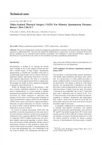
In terms of our model several (stacked) networks can be distinguished in this situation. The lowest network is the physical network (not drawn in the figure). It includes the physical cable (= the physical network connection) and the electronics within the PC that control its data transport (= the adaptors). Then there is a layer 2 network taking care of the Ethernet protocol. Then there are higher-level networks stacked on top of these networks, e.g. an IP network), and this continues up to (at least) the application level. In Figure 1 these networks are drawn horizontally and typically consist of an adapter in one PC talking to an adapter in the other PC. Secondly, the stack within a PC also maps onto several networks in our model. These networks consist of two protocol drivers associated with different levels in the stack, since the calling and called protocol drivers in the stack together form a network (as explained above). In Figure 1 these networks are drawn vertically. In our model's parlance, we say that the physical connection tunnels the ethernet connection, which in turn tunnels the IP connections. Connections (C) can be set up, used, and broken down. Each connection is part of one network, and hence is associated with only one protocol. Connections can be stacked called 'tunneling' in the model - in a similar way as networks and protocols are stacked. Connections exist so data packets can traverse them. As within this model only adapters set up connections, setting up a physical connection (i.e. connecting cables) is outside the scope of this model; physical connections either exist, or they do not. The model does not require that connections be set up by following some protocol steps (as in TCP); the mere fact that a data packet has been received implies that a connection must have existed. So, even multicast protocols or unreliable protocols such as UDP use connections. A graphical representation of the network model is depicted in Figure 2. tt
tunnel
u1
s A
c1 P
C
u2
t
b rx tx
trv
ipo1
c2
DP
encap
ipo2
N c3
Figure 2: Network model
20
Koninklijke Philips Electronics N.V. 2003
Unclassified
Abbr Concept . N Network P A
Protocol Adapter
DP C
Data Packet Connection
Abbr. c1 c2 c3 t ipo1 ipo2 rx tx encap tunnel trv s b u2 u1 tt
# 1. 2. 3. 4. 5. 6. 7. 8.
PR-TN-2003/00399
Description E.g.: LAN at the author’s home, KPN backbone network. E.g.: ATM, Ethernet, IP, UDP, FTP, etc. E.g.: a NIC, a computer, an RG, Ethernet driver, networking OS component, an OS, an FTP client or server, etc. E.g.: an IP datagram, an Ethernet packet, etc. E.g.: a UTP cable between two NICs, or an IPSEC pipe.
Relation Protocol p1 carries protocol p2. Network n carries protocol p. Network n1 carries network n2. Adapter a talks (speaks) protocol p. Adapter a is part of network n. Connection c is part of network n. Adapter a receives data packet dp. Adapter a transmits data packet dp. Data packet dp1 encapsulates data packet dp2. Connection c1 tunnels connection c2. Data packet dp traverses connection c. Adapter a sets up connection c. Adapter a breaks down connection c. Adapter a uses connection c. Adapter a1 uses (calls) adapter a2 to obtain a service that a2 offers. Think of this as a1 stacked on top of a2. Adapter a1 talks to adapter a2. Think of this as a1 talking to a2 on the same level in the protocol stack. Rule
A network n carries one and only one protocol. An adapter talks at least one protocol. Adapters may however talk multiple protocols. Hence adapters can be part of more than one network. A connection is part of one and only one network. A data packet is transmitted by one and only one adapter.
All adapters a that are part of network n talk (at least) the protocol p that is carried by network n. If adapter a1 has talked to adapter a2, then both adapters are part of the same network. If adapter a has used a connection c, then both a and c are part of the same network. If an adapter a has broken down a connection c, then it must also have set up that connection.
Koninklijke Philips Electronics N.V. 2003
21
PR-TN-2003/00399 # 9.
Unclassified
Rule
If connection c is part of network n, then the connection has been set up by an adapter that is also part of network n. Data Transport 10. Adapter a1 can only talk to adapter a2 if they speak the same protocol. 11. If adapter a has received data packet dp, it has used a connection c that data packet dp has traversed. 12. If adapter atx has talked to adapter arx, it has transmitted a data packet dp that was received by arx. Also, if atx has transmitted a data packet dp that was received by arx, then atx has talked to arx. Thus, ‘talk to’ implies not only that a data packet has been transmitted but that data packet must have been received as well. Therefore, a broadcast cannot be modeled with a ‘talk to’ relation. 13. If adapter atx has talked to adapter arx, they have both used the same connection. 14. If adapter ah has setup a connection ch, then ah has used an adapter al that has used a connection cl which tunnels ch. Stacking 15. If adapter al, being part of network nl, has been used (called) by adapter ah which is part of network nh, we then say that network nl carries network nh. 16. If adapter ah has used (called) adapter al for transmitting a data packet dpl that encapsulates data packet dph, we then say that adapter ah has transmitted data packet dph. 17. If adapter ah has used (called) adapter al for receiving a data packet dpl that encapsulates data packet dph, we then say that adapter ah has received data packet dph. 18. If connection cl tunnels connection ch, then there are adapters al and ah such that al uses cl and ah uses ch, while ah uses (calls) al. 19. If adapter ah talks protocol ph, and ah uses (calls) adapter al which talks protocol pl, we then say that protocol pl carries ph. 20. If data packet dph traverses connection ch, and dph is encapsulated in data packet dpl which traverses connection cl, we then say that cl tunnels ch. 21. If data packet dph is encapsulated by data packet dpl that traverses connection cl that tunnels connection ch, we then say that dph traverses ch. Network Security 22. if data packet dp has been received by adapter a1, then no other adapter has received dp.6 23. if adapter a1 has received a data packet dp, then there is an adapter a2 that has transmitted dp.7
6
This rule must only be applied to networks that need to transport data confidentially. Note that this rule implies that networks that carry multicast or broadcast protocols cannot be confidential. 7
22
This rule expresses the integrity of data packets.
Koninklijke Philips Electronics N.V. 2003
Unclassified
PR-TN-2003/00399
2.1.2. Applications This model is about applications running in some electronic equipment and how users (and other applications) can obtain functionality from an application. Basically, the model applies to all electronic equipment that has, or can be thought of as having software inside of it and that may be connected, through a physical connection (cable, or wireless connection), to other electronic equipment. The central concept in this model is the application component (AC). The reason for this is that we require application components to run in a single box, e.g. computer hardware or switch box, whereas an application might be distributed over several boxes. We consider applications to consist of one or more application components. However we have chosen not to include (distributed) applications in our model. Examples of application components are an email client, operating system components, or firewall software. Application components run in a single box, e.g. computer hardware or switch box, or a Residential Gateway. Application components may run on other application components (e.g. operating system components). Furthermore, application components provide a unique functionality that users and/or other application components can obtain by calling the unique interface provided by the application component. In order to provide their functionality, application components may talk to other application components, possibly running in another box. The latter option provides for networking applications to be described by the model, although no actual modeling of the network is done. A user (in this model) is any one (human) or any application component that obtains functionality from another application component by calling its (user) interface. In this model, we assume that there is always a user that obtains some functionality once such functionality is provided, or once an interface is called.
Koninklijke Philips Electronics N.V. 2003
23
PR-TN-2003/00399
Unclassified
A graphical representation of the model for applications is depicted in the figure below. r
u1
tt1 AC
iaa U
in1
p
obt
tt2
F
o
c
B
in2
plug u2
I
C
Figure 3: Applications model
Abbr Concept Description . AC Application E.g.: Windows OS, Network Management System, FTP (Component) Client, Webserver, Dynamic Link Library, Firewall software, etc. B Box E.g.: computer hardware, network element hardware, switch box, etc. C Cable E.g.: UTP or STP cable, coax, serial/parallel cables, etc. F Functional- A set of functions or procedures (actions) offered by an ity application component. I Interface An interface can be thought of as the set of methods that an application component offers for obtaining functionality. Interfaces include: user interfaces, component - component interfaces (calling interfaces), networking interfaces, etc. U User Anyone or anything that needs some functionality off an application (component). Note that application (components) themselves are users. While not formally modeled this way, it seems fair to assume that non-AC type users are human. Abbr. u1 u2 Iaa 24
Relation User u uses application (component) ac. Box b uses cable c. Application (component) ac is also a user u.
Koninklijke Philips Electronics N.V. 2003
Unclassified
Abbr. c obt p o tt1 tt2 r in1 in2 plug # 1.
PR-TN-2003/00399
Relation User u calls interface i. User u obtains functionality f. Application (component) ac provides functionality f. Application (component) ac offers (publishes) interface i. Application (component) ac1 talks to application (component) ac2. Box b1 talks to box b2. Application (component) ac1 runs on application (component) ac2. Application (component) ac runs in box b. Interface i resides in box b. Cable c plugs into box b.
Rule
user u has used application component ac if and only if user u has obtained a functionality f that has been provided by application component ac. 2. If a user u has used an application component ac, then the user has called an interface i that has been offered (published) by ac. 3. If a user u has obtained a functionality f, then u has used an application component ac that has provided f. 4. Every application (component) is in at least one box. 5. Any given functionality is provided by one and only one application component. 6. If an application component ac has provided a functionality f, then a user u has used the application component and u has obtained the provided functionality. 7. Saying that 'application component ac1 has talked to application component ac2' is identical with saying 'application component ac1, in its role as user, has obtained a functionality f provided by application component ac2'. 8. Saying that 'application component ac1 has talked to application component ac2' is identical with saying 'application component ac1, in its role as user, has called an interface i offered (published) by application component ac2'. 9. If an application component ac1 has run on application component ac2, then ac1 has talked to ac2. 10. If an interface i is in box b then i has been offered (published) by an application component that is also in box b. 11. If a box b has used cable c, then cable c has been plugged into box b. 12. If a box b1 has talked to box b2, both boxes have used some cable c.
Koninklijke Philips Electronics N.V. 2003
25
PR-TN-2003/00399
Unclassified
2.1.3. Service Provisioning This model is about service providers providing services to users.
ru
rsp
az t
U
SP at
iaa p
obt iwi
o SVC
Figure 4: Service provisioning model
As can be seen in Figure 4 this model consists of only three concepts: user, service and service provider. From the point of view of the service provider the model basically describes the different stages between offering a service, i.e. claiming “I can provide a certain service”, and actually providing the service to a user. First, the service provider needs to offer a certain service, for example via a website. If a user wants to obtain this service he needs to express interest in the service (for example via a subscription to a service, or via a direct service request). After this the service provider needs to decide whether or not to provide the requested service to the user. Making this decision is called authorization, i.e. ensure - by the business rules of the service provider - that the user is actually entitled to the service. Only if the user is authorized the service will be provided and the user will actually obtain the service. In our model the service provider must ensure that the user that expresses interest in his service, is in fact the user that he claims to be (this is authentication). Therefore all authorizations are preceded by an authentication. Note that an authentication method only provides a certain level of certainty: the better the authentication method, the more certain the service provider can be about the users identity. By using an authentication method with zero level of certainty this model can therefore even cover situations where a service provider does not care about the users identity at all. The most interesting part of the model deals with 'trust propagation'. Users can delegate service acquisition (e.g. to a clerk or a computer program); they are then represented by 26
Koninklijke Philips Electronics N.V. 2003
Unclassified
PR-TN-2003/00399
another user. In fact, this other user provides a (representation) service, and as such, needs to be treated as a service provider (which is formally modeled via the 'is also a'relation). Therefore the user that provides the representation service (the so-called representing user) needs to authorize, and with that authenticate, the user that wants to be represented (the so-called represented user). In addition the model states that any services that the representing user expresses an interest in, or actually obtains, are considered to be interesting for (or obtained by) the represented user as well. If this were not the case, then a service provider would have trouble in deciding which of the users to authenticate. Similarly, service providers can delegate service provisioning (e.g. to a server computer); they are then represented by another service provider. Then, any services offered or provided by the representing service provider are considered to be offered or provided by the represented service provider. Therefore the represented service provider is still liable in case something goes wrong with the service provisioning. Abbr. U
Concept User
SP
Service Provider
SVC
Service
Abbr. iwi
Relation User u wants (wishes) a service s (“I want it”). Or perhaps: user has demonstrated interest in service s. User u obtains a service s. Service provider sp provides service s. Service provider sp offers service s. Service provider sp authorizes user u. Service provider sp authenticates user u. User u1 represents user u2. Service provider sp1 represents service provider sp2. User u is also a service provider sp.
obt p o az at ru rsp iaa
Description Anyone or anything that obtains, or wishes to obtain some service from a service provider or another user (e.g. a human being, a legal entity, or a computer application). N.B.: some restrictions refine this notion. Anyone or anything that provides, or (at least) offers, a service (e.g.: a human being, a legal entity, or a computer application). N.B.: some restrictions refine this notion. The thing (tangible or intangible) that a service provider offers (and provides) and that a user (wants to) obtain(s).
Koninklijke Philips Electronics N.V. 2003
27
PR-TN-2003/00399
# 1. 2.
Unclassified
Rule
If a service provider sp has provided service s, then sp has offered s8. If a service provider sp has provided service s, then sp has authorized a user u that has shown interest in service s. 3. If a user u has obtained a service s, then u has shown interest in s 4. If a user u has obtained a service s, then u has been authorized by the service provider that has provided s. 5. If a service provider sp has authorized user u, then sp has authenticated u. 6. If a service provider sp has authorized user u, then sp has offered a service s in which u has shown interest. Representation 7. If user u1 represents user u2, then u1 is also a service provider sp that has authorized user u1. 8. If service provider sp1 represents service provider sp2, then sp1 is also a user u that sp2 has authorized. 9. If user u1 is represented by user u2, and user u2 has obtained service s, then user u1 has obtained service s. 10. If user u1 is represented by user u2, and user u2 has shown interest in service s, then user u1 has shown interest in service s. 11. If service provider sp1 is represented by service provider sp2, and sp2 has provided service s, then sp1 has provided s. 12. If service provider sp1 is represented by service provider sp2, and sp2 has offered service s, then sp1 has offered s.
2.1.4. Integrated Network Services In order to form integrated Network Services the three models described in the sections above need to be combined. This is done by deciding which relations in one model map onto which relations in another. Let us, for example, assume that there is an application component ac1 that talks to application component ac2 (as can be expressed in the Application model). We can easily also think of these application components as if they were network adapters that talk to each other. So we decide that the relation tt1 (from the Application model) maps onto relation tt (from the Network model). This decision has consequences, namely that as the application components can now be thought of as if they were network adapters, they must also satisfy the relations and rules for network adapters. For example, if an application component speaks to another application component, they both must speak the same protocol. See the network model for the other rules that must apply. In this section, we define the Integrated Network Services model, which consists of - the Application, Network, and Service Provisioning models as described in previous sections, and - a list of mappings of relations between these models. 8
28
This seems reasonable - how else would a user know of their existence?
Koninklijke Philips Electronics N.V. 2003
Unclassified
PR-TN-2003/00399
Because we need a notation for referring to relations of specific models, we prefix such relations as follows: - prefix A: is used for relations from the Application model - prefix N: is used for relations from the Network model - prefix SP: is used for relations from the Service Provisioning model For example, A:tt1 represents relation tt1 from the Application model. Mappings between Integrated Application and Network models The following table describes the mapped relations between the Application and Network model, where A and N refer to Application and Network model respectively: Mapping Description A:tt1 ⊆ N:tt Application components are adapters. Whenever an application component ac1 talks to application component ac2, then all rules (from the Network model) must hold that apply when an adapter a1 (being the same as ac1) talks to adapter a2 (= ac2)9. A:tt2 ⊆ N:tt Boxes are adapters. Whenever a box b1 talks to a box b2, all restrictions must hold that apply when an adapter a1 (=b1) talks to an adapter a2 (=b2). A:r ⊆ N:u Application components are adapters. 1 Whenever an application component ac1 runs on application component ac2, then all restrictions must hold that apply when an adapter a1 (=ac1) uses adapter a2 (=ac2). A:in ⊆ N:u Application components are adapters. 1 Boxes are adapters. 1 Whenever an application component ac runs in a box b, then all restrictions must hold that apply when an adapter a1 (=ac) uses adapter a2 (=b). A:u2 ⊆ N:u Boxes are adapters. 2 Cables are connections. Whenever a box b uses a cable c, all restrictions must hold that apply when an adapter a (=b) uses a connection c' (=c). The integrated model describes users and (stacked) application components, interconnected by (stacked) networks. In this integrated model cables are network connections and application components and boxes are network adapters that talk to, or use one another as described by the network model. This implies that application components only talk to one another by transmitting and receiving data packets over a connection. Hence, 9
This sometimes gives rise to some confusion, e.g. that adapter a1 does not support other application components than ac1. However, conceptually speaking a1 and ac1 are the same, although a1 is its designation from the networking perspective (and hence seen as an adapter), while ac1 is seen as an application component from the application model's point of view.
Koninklijke Philips Electronics N.V. 2003
29
PR-TN-2003/00399
Unclassified
a term such as 'software calling mechanism' is modeled as a connection through which data packets can travel according to a protocol. Also, application components that use such an interface, together with the application component providing that interface, make up a network.10 Boxes talk to one another using hardware calling mechanisms (both for signaling and data transfer), which are also modelled as a network connection. Hence, boxes talk to one another by transmitting and receiving data packets through a cable, talking a (one) protocol. Confidentiality and Integrity in inter-application component communication are also governed by the corresponding (optional) rules of the network model. Mappings between Integrated Application and Service Provisioning models The following table describes the mapping between the Service Provisioning and Application model, where SP and A refer to Service Provisioning and Application model respectively: Mapping Description ⊆ SP:obtain Functionality is a service Whenever a user obtains functionality, then all restrictions must hold that apply when a user obtains a service. A:p ⊆ SP:provid Application components are service providers. e Functionality is a service. Whenever an application component provides functionality, all restrictions must hold that apply when a service provider provides a service. A:iaa ⊆ SP:Liaa Application components are service providers A:obt
The integrated model describes that the way users obtain functionality from application components is identical with users obtaining services from service providers. In this integrated model, application components are service providers and functionality is a service. This implies that application components need to authorize and authenticate users before actually providing the functionality.
10
The reader may object to this paragraph as its contents diverges from conventions such as the OSI model. However, models (including the OSI model) are just means of looking at parts of the world (in this case: networks), and should be used only if they in fact are useful: different models can do different things, and the 7 network layers in the OSI model are not particularly useful from a security point of view. For instance, the TCP/IP protocol suite can only forcefully be mapped onto the OSI model. Another example is NetBIOS (NetBEUI), that have different implementations on different levels in network stacks, and as such cannot be easily assigned an OSI level. While our network model may not adapt easily to the OSI model (and vice versa), it is much more compliant with the more recent ITU-T Recommendation G.805 (Generic Functional Architecture of Transport Networks).
30
Koninklijke Philips Electronics N.V. 2003
Unclassified
PR-TN-2003/00399
Because application components are considered to be service providers, they can delegate the provisioning of functionality to another application component. Furthermore, an application component (in its identity as a user of another application component) can delegate the acquisition of the functionality to some other application component.
Koninklijke Philips Electronics N.V. 2003
31
PR-TN-2003/00399
2.2.
Unclassified
Generic Content and Data
In this section, we present models with respect to content, data representing such content, and the processing thereof. The first model focuses on rights assigned to users for performing actions, e.g. play or copy, on information and data, whereas the second model focuses data representing content and the processing thereof. After discussing these reference models separately we will combine the two models into an Integration model. 2.2.1. Content, Information, Data and Rights This model discusses the terms 'content', 'information', and 'rights', and provides a basic terminology and semantics on which digital rights management can be built. The central ideas here are that content is (intangible) information that is owned by a content owner. The content owner may tell what actions can be done with the content. In other words: the content owner has all rights to the content information. However, no one can do something with content information unless it is represented by some kind of data - dubbed 'content data' - of which there can be various different kinds (a picture, for instance, can be represented in a GIF image, a JPEG image, or by ink on a piece of paper). Similarly, rights are not useful (at least not within an RGE) unless they, too, have a data representation - dubbed 'rights data'. Rights data must refer to content data, and allow an action on that content data. Thus, they represent a (generic) right to the content represented by the content information. Rights data are generated by the content owner, which also generates the content data11.
11 This does not mean that the content owner himself actually generates the content data (or rights data). He can have delegated this operational job to someone else. However, this other person does so on behalf of the content owner, and as such the content owner can be thought of as having generated the content data (or rights data).
32
Koninklijke Philips Electronics N.V. 2003
Unclassified
PR-TN-2003/00399
A graphical representation of the content, information, data and rights model is given below: allow2 R
A
repr2 allow RD
isa
on2
act ref
gen2
CR
own2
on1
CO
own
gen
CD
repr
CI
Figure 5: Content information, Data and Rights model
Abbr. A
Concept Action
CD
Content Data
CI
Content Information Content Owner Content Right Right
CO CR R RD
Right Data
Description The set of all possible actions on content data. Examples: play, copy, distribute, render, etc. The physical representation of a piece of content (information). It is the data that represents a piece of information. Examples: a file 'mypicture.jpg', a book 'Sprookjes van Moeder de Gans', etc. The actual content as referenced by content data, e.g. the actual story in a book (not the book, or the letters, but the information it conveys). The entity that owns information, and controls the rights on that information. A (generic) right tied to a piece of content. For example: the right to play the film 'Sound of Music'. A generic right. Think of this as the right to copy, the right to distribute, the right to play, etc. The physical representation of a right (information). It is the data that represents a right. Examples: a certificate granting the right to distribute a movie, a key unlocking a data file that can subsequently be viewed, etc.
Koninklijke Philips Electronics N.V. 2003
33
PR-TN-2003/00399
Abbr. allow allow2 gen gen2 isa on1 on2 act own own2 ref repr repr2
Unclassified
Relation Rights data rd allows action a. Right r allows action a. Content owner co generates content data cd. Content owner co generates rights data rd. Content right cr is a right r. Content right cr (is a content right) on content information ci. Action a (is an action) on content data cd. Action a has acted on content data cd. Content owner co owns content information ci.12 Content owner co owns content right cr. Rights data rd references content data cd. Content data cd represents content information ci. Rights data rd represents right r.
# Rule Cardinalities 1. Any (generic) right r allows one and only one action a. 2. Any content right cr is a content right on one and only one content information ci. 3. Any rights data rd references one and only one content data cd. 4. Any content data cd represents one and only one content information ci. 5. Any content data cd is generated by one and only one content owner co. 6. Any rights data rd is generated by one and only one content owner co. 7. Any content information ci is owned by one and only one content owner co. 8. Any content right cr is owned by one and only one content owner co. Equivalencies (Definitions) 9. A rights data rd allows an action a if and only if rd represents a (generic) right r that allows a. Other restrictions 10. If an action a has acted on content data cd, then a is an action on cd.13 11. If an action a has acted on content data cd, then there is a rights data rd that allows a, and rd also references cd. 12. If content owner co has generated content data cd, then co owns the content information ci that cd represents. 12
Given the natural language representations of the relations 'act' and 'on2' it might seem that they are identical. However, the relation 'on2' refers to the ability of an action to operate on content data, while 'act' refers to the actual acting. The difference becomes apparent in rule 11 (If an action a has acted on content data cd, then there is a rights data rd that allows a, and rd also references cd), which uses the relation 'act'. If this were replaced with the relation 'on2', rule 11 would read as: 'if an action a is an action on content data cd, then there is a rights data rd that allows a, and rd also references cd'. Obviously, this rule would not always be true, as the action may not have yet taken place. 13
This rule seems trivial, in particular when presented as a natural language sentence. However 'trivial' rules like this can be a crucial part of logical reasonings that can be held in the formal model, and hence should not be omitted.
34
Koninklijke Philips Electronics N.V. 2003
Unclassified
# 13. 14. 15. 16. 17.
PR-TN-2003/00399
Rule If content owner co owns a content right cr, that is a (generic) right r represented by some rights data rd, then co has generated rd. If content owner co owns a content right cr on content information ci, then co owns ci. If rights data rd references a content data cd, then rd is generated by the same content owner co that generated cd. If rights data rd references a content data cd, then rd allows an action a on cd. If content data cd represents content information ci, then the cd has been generated by the content owner co that owns ci.
2.2.2. Information, Data Users and Equipment This model is intended to act as a common frame of reference for the processing of content data representing (content) information. The idea is to link the processing of data that represents content (information) to users consuming this information. Such a link is imperative if we want to talk about DRM, and ultimately get some money for the content that is provided. If data is being processed, i.e. there is a process that operates on some data, there is also a processor (computer, or human) executing this process. If the processor is a machine (computer, VCR, etc), this machine executes said process on behalf of the user that uses this machine, so it is valid to say that this user actually executes the process, thereby using the data. By using data that represents content information, we say that the user consumes said information. A graphical representation of this model is given below: D
typeof
DT
repr
oo
I
use2
req
cons
proc exec2
P
exec1
U
use1 EQT
Figure 6: Information, Data users and Equipment model
Koninklijke Philips Electronics N.V. 2003
35
PR-TN-2003/00399
Abbr. D
Concept Data
DT
Data Type
Eqt
Equipment
I
Information
P
Process
U
User
Abbr. cons exec1 exec2 oo proc repr req typeof use1 use2 #
Unclassified
Description Think of this as a book (in which a story is written down), or a celluloid film (that can be put in a projector to show a movie), or a piece of data in a computer. This is the set of data types that content can be represented with, e.g.: book, celluloid film, JPEG-file, etc. Equipment is a piece of machinery, such as a computer, that can be used by a user for executing processes. Think of this as a story, information about a person, a movie, etc. without thinking about how this information is carried. A series of actions or operations conducing to an end, either automated (executed by a piece of equipment), or manual (executed by a person). A user is a person or a piece of equipment that uses data, executes processes, and such.
Relation User u consumes information i. Equipment e executes process p. User u executes process p. Process p operates on data d. Process p processes data d. Data d represents information i. Process p requires data of type dt. Data d is of data type dt. User u uses equipment e. User u uses data d. Rule
Cardinalities 1. Every process is executed by at least one user. 2. Every user has at least executed one process. 3. Every data d represents at least one piece of information i. 4. Every piece of information is represented by at least one data d. 5. Every data d is of one and only one data type dt. 6. Every process p requires one and only one data type dt. Equivalencies (Definitions) 7. Process p operates on data d if and only if p also operates on d. Other restrictions 8. If a piece of equipment e executes a process p, then there is a user u that uses data d that is operated on by p. 9. If a user u uses data d, then u consumes the information i that is represented by d. 36
Koninklijke Philips Electronics N.V. 2003
Unclassified
PR-TN-2003/00399
# Rule 10. If a user u consumes information I, then u uses some data d that represents i. 11. If a user u uses a piece of equipment e that executes process p, then we say
that u executes p (as well). 12. If a user u uses data d, then u executes a process p that operates on d. 13. If a process p operates on data d, then there is a user that both uses d, and
executes p. 14. If a process p has operated on data d, then p requires data type dt.
2.2.3. Integrated model In order to form an integrated model for content, data, rights, users, and equipment, the two models described in the sections above need to be combined. This is done again by deciding which relations in one model map onto which relations in the other. In this section, we need a notation for referring to relations of specific models. To this end, we prefix such relations as follows: - prefix IDUE: is used for relations from the Information, Data Users and Equipment model - prefix CIDR: is used for relations from the Content, Information, Data and Rights model For example, IDUE:proc represents relation proc from the Information, Data Users and Equipment model. The following table describes the mapped relations between the Information, Data Users and Equipment model (abbreviated by IDUE model), and the Content, Information, Data and Rights model (designated by CIDR in the table) Mapping IDUE:pro ≡ CIDR:act c
Description Data is Content Data Processes are Actions Processing data, or acting on content data, are equivalent. Hence, all restrictions applying to 'proc' also apply to 'act', and vice versa. For example, if an action a acts on content data cd, then there is a user that executes a, and uses cd. IDUE:rep ≡ CIDR:repr Data is Content Data Information is Content Information r Data representing information and content data representing content information, are equivalent. Hence, all restrictions that apply to the relation repr from IDUE also apply to the relation repr from CIDR. For example, if a user u consumes content information ci, then u uses some content data cd that represents ci.
Koninklijke Philips Electronics N.V. 2003
37
PR-TN-2003/00399
Unclassified
The consequences of these mappings are that if content data, when operated on by some process, means that this content data is owned by a content owner that has not only generated the content data14, but also rights data that refer to this content data, and that are necessary for the processing to take place. This processing of content data further implies that there is a user that consumes the information the processed data represents. This model provides a basis onto which payment mechanisms can be installed, as it formalizes the notions of users consuming information owned by content owners. Integration of the IDUE and CIDR models with the service provisioning models leads to the following additional constraints: Mapping IDUE:cons; ⊆ SP:obt; SP: prov CIDR:own
Description IDUE:Users are SP:Users Content Owners are Service Providers If a user u consumes information i that is owned by content owner co, then u has obtained a service s from service provider/content owner co.
One of the consequences of this rule is that the consumer (u) must be authorized by the content owner to consume the information (i). From the generic security models, it then follows that u must have been authenticated, etc.
14 This does not mean that the content owner himself actually generates the content data and rights data. He can have delegated this operational job to someone else. However, this other person does so on behalf of the content owner, and as such the content owner can be thought of as having generated these data.
38
Koninklijke Philips Electronics N.V. 2003
Unclassified
2.3.
PR-TN-2003/00399
Generic Security
In this section, we present a frame of reference for several generic security issues. First we model entity registration, authentication and authorization. Then, we continue with contracts, Role Based Access Control (RBAC), and Privacy. After discussing these reference models separately we will combine them in an Integration model for generic security issues. 2.3.1. Registration This model is about registered entities, i.e. entities that have been registered at some institution that we call a 'registration authority'. Registered entities can be anything, ranging from persons, computers, and organizations to tokens that reference the identity of some registered entity. The registration authority registers the identity of its registered entities, and issues tokens that refer to these identities. Identity tokens include digital identity certificates, passports, drivers licenses, username/password combinations, but a piece of paper with the name of a registered entity could do just as well15. We only require that the token references in some way the identity of the registered entity. There is a subtlety in the way we talk about identity tokens belonging to a registered entity, and identity tokens (being registered entities as well) being owned by a registered entity. When we say that an identity belongs to a registered entity, this is to say that the token references an identity that the registered entity has. Ownership is different, as is illustrated by the example where an identity token (e.g. a digital certificate) identifying a computer can hardly be owned by the computer. However, it is useful to say that an identity token has a registered entity as its owner, allowing that this registered entity is not the registered entity does not have the identity that the identity token references. Also, there is a registration authority that has issued the tokens' token, stored the tokens identity, and thus has registered the token. Thus, by choosing to think of an identity token as a registered entity, an identity token (e.g. a digital certificate) identifying a computer can be owned by the owner of that computer. If asked who would 'own' a human registered entity (= an individual person), one might say that, unless this human is a slave, it owns itself. Naturally, we require that each registered entity has a unique owner. Furthermore we have modeled ownership inheritance: if a registered entity re1 owns a registered entity re2, which in turn owns another registered entity re3, we then say that re1 also owns re3.
15
For instance, a paper confirming your room reservation in a hotel could also be used as an identity token.
Koninklijke Philips Electronics N.V. 2003
39
PR-TN-2003/00399
Unclassified
1:1
RA
issue store reg 1:1
IdT
Id
has
ref
isa
RE
1:1
1:1
bt
own
Figure 7: Registration model
Abbr Concept . RA Registration Authority RE Registered Entity
Id IdT
Identity Identity Token
Abbr. isa reg has own store bt ref issue
Description A party that registers entities, and issues tokens to such entities as proof of that registration. An entity (person, organization, equipment, etc.) that is registered with a Registration Authority (e.g. TNO Telecom's Mailserver#1, the person called Rieks Joosten, etc.) A name of a registered entity (e.g. Pete Shandler) A token that refers to the identity of a registered entity.
Relation Identity Token idt is a Registered Entity. Registration Authority ra has registered Registered Entity re. Registered Entity re has identity id. Registered Entity re1 owns Registered Entity re2. Registration Authority ra stores Identity id. Identity Token idt belongs to Registered Entity re. Identity Token idt references identity id. Registration Authority ra issues Identity Token idt.
# Rule 40
Koninklijke Philips Electronics N.V. 2003
Unclassified
PR-TN-2003/00399
# Rule 1. Any registered entity is owned by one and only one registered entity. 2. Any identity token is issued by one and only one registration authority. 3. Any identity is had by one and only one registered entity. This means that an identity is unique. (A registered entity can be registered many times, but any time with a different identity) 4. Any identity token belongs to one and only one registered entity. 5. Any identity token references one and only one identity. 6. If an identity token idt belongs to registered entity re, then the registration authority ra that has issued idt, has also registered re. 7. If a registration authority ra has issued identity token idt, and idt references identity id, then ra has stored the id. 8. If a registration authority ra has stored identity id, then ra has registered a registered entity re that has identity id. 9. If a registration authority ra has registered a registered entity re1, and re1 is owned by re2, then ra has registered re2. 10 If a registered entity re1 owns a registered entity re2, which in turn owns a registered entity re3, then re1 owns re3 (as well). 2.3.2. Authentication This model is about entity authentication. Authentication is the process in which a verifier accepts or rejects the alleged identity of an entity. Only if the verifier has accepted the alleged identity, we can say that the corresponding entity is authenticated. The authentication process starts with an entity declaring an identity (e.g. a name, a serial number, a unique bit string) by showing an identification token (e.g. a digital certificate, passport, a username/password), which references the declared identity. The verifier checks this identity token by executing an authentication method for the type of identity token at hand. For example, for passports the photo will be checked against the face of the entity that shows the passport, the validity date will be checked, and perhaps other attributes of the passport are checked. The result of this is either an accepted or rejected identity token. With accepting the identity token the verifier also accepts that the identity referenced by the identity token is an identity of the entity that has shown the token. In the model, accepting the identity token is equivalent with saying that the verifier has authenticated the entity. Note that we require an identity token to reference precisely one identity. Also, an authentication method can only be used on identity tokens that are of the (one) type that the authentication method accepts. But while one authentication method only accepts tokens of one type, a token of a given type may be checked by different authentication methods (e.g. a passport can be checked by executing a method that examines the passport thoroughly (as with the customs), or it can be checked by executing a method that examines only the photograph. Each of these methods has its own properties and provides its own level of trust in the declared identity that the token is referring to.
Koninklijke Philips Electronics N.V. 2003
41
PR-TN-2003/00399
Unclassified
A graphical representation of the authentication model is depicted below:
autc E
V
isa
exec
vfy
dtii
1 :N
shows
checks
Id 1:
1
AM
ref
type of
req
1:
IdT
1
accepts
1:N
1:1
Id Type
Figure 8: Authentication model
Abbr. Concept E Entity V Verifier Id IdT IdType AM
Abbr. autc isa dtii vfy shows ref checks accepts exec req typeof 42
Description Think of a person, a piece of equipment, or an organization A person or a piece of equipment that verifies the identity of an entity Identity A name of a registered entity (e.g. Pete Shandler) Identity Token A token that refers to the identity of a registered entity. Identity token Type of identity token. Think of 'passport', 'driverslicense', type 'X509 identity certificate', 'company card', etc. Authentication Method that decides whether or not to accept an identity Method token. Relation Verifier v has authenticated entity e. Verifier v is an entity e. Entity e declares that it has identity id. Verifier v verifies identity id. Entity e shows identity token idt. Identity Token idt references identity id. Verifier v checks identity token idt. Authentication method am accepts identity token idt. Verifier v executes authentication method am. Authentication method am requires id tokens of identity token type idtype. Identity token idt is of type identity token type idtype.
Koninklijke Philips Electronics N.V. 2003
Unclassified
PR-TN-2003/00399
#
Rule Any identity token references one and only one identity. Any identity token has one and only one identity token type. Any authentication method requires one and only one identity token type. Any verifier has checked one or more identity tokens. Any verifier has executed one or more authentication methods. If a verifier v has authenticated entity e, then v has verified identity id that e has declared that it has. 7. If an entity e has declared that it has identity id, then e has shown an identity token idt that references id. 8. If a verifier v has checked identity token idt, then v has executed an authentication method am that requires idt to be of a type idtype. 9. If an authentication method am has accepted identity token idt, then there is a verifier v that has checked idt by executing am. 10. If a verifier v has verified identity id, then v has executed an authentication method am that has accepted an identity token idt that references identity id. 1. 2. 3. 4. 5. 6.
2.3.3. Authorization This model is about entity authorization. Authorization is the process in which an authorizing party allows an entity to do something, where 'something' can be pretty much anything. You could think of accessing a database, accessing directories, opening a door to a restricted area, view a movie, distribute a game, doing a bungee-jump, buying medicines, etc. The entity, however, cannot do this 'something' just like that. It must be authorized to do so by the party that is responsible for that something. This party is therefore indicated with authorizing party, for example a system administrator, a content provider or an organization selling tickets for a concert. To simplify matters we have chosen to think that every something is the responsibility of precisely one party, and hence only that party can authorize an entity to do that something. The model does not say anything about how an authorizing party decides whether or not to authorize an entity to do something. In most cases the authorizing party will perform some form of entity authentication but that is outside the scope of this model. The model however does state that when the authorizing party has decided to authorize an entity to do something, it needs to issue a right for doing that something. We have chosen that a right is associated with only one something. If an entity is allowed to do more 'something's, it consequently needs to have multiple rights. Such a right can for example be a mark for read-access in the access table for a certain directory or a ticket for a concert.
Koninklijke Philips Electronics N.V. 2003
43
PR-TN-2003/00399
Unclassified
A graphical representation of the authorization model is depicted below.
1:1
E
autz iatd has 1:n 1:1
AP
S 1:1
irf
todo
1:1
R issues
Figure 9: Authorization model
Abbr Concept . E Entity S Something R
Right
AP
Authorizing Party
Abbr. iatd issues
Description Think of a person, a piece of equipment, or an organization Think of accessing a database, opening a door to a restricted area, view a movie, distribute a game, doing a bungee-jump, etc Think of right to access a database, right to play a cd, right to visit a concert Party that is responsible for “something” the entity wants to do. Think of a system administrator, music distributor, content provider, etc
has
Relation Entity e is allowed to do something s. Authorizing Party ap issues right r. Entity e has right r.
autz
Authorizing Party ap authorizes entity e.
irf
Authorizing Party ap is responsible for something s.
todo
Right r to do something s.
44
Koninklijke Philips Electronics N.V. 2003
Unclassified
PR-TN-2003/00399
#
Rule
1. 2. 3.
Any something is the responsibility of precisely one authorizing party Any right allows only one something to be done If an entity e has been allowed to do something s, then e has been authorized by the authorizing party ap that is responsible for s. If an authorizing party ap has authorized an entity e, then ap has issued a right r that e has. If an entity e has been allowed to do something s, then e has had the right r to do s. If an entity e has been allowed to do something s, then e has had the right r that was issued by authorizing party ap that is responsible for s.
4. 5. 6.
Koninklijke Philips Electronics N.V. 2003
45
PR-TN-2003/00399
Unclassified
2.3.4. Contracts This model focuses on contracts, which are thought of as to contain sets of rules (the rule sets), each of which addresses some topic. There may be a rule set governing quality of service, and another one governing security. There is a 1-1 correspondence between such topics and rule sets. Rule sets contain rules, and each rule in the rule set addresses the topic addressed by the rule set. It may also contain other topics, i.e. a rule may belong to multiple rule sets. We assume that the contract parties that have committed themselves to a contract have fulfilled all rules (in the rule sets) of the contract at each point in time. At least, that is what contracts are for: they define rules that contract parties have to abide by. From this it follows that contract parties fulfill their contract by fulfilling all rule sets contained in that contract, which is the same as fulfilling all rules in that contract. RS c1 a1 c3
ff1
T C
c2
a2 R ff3
ff2
CP commit
Figure 10: Contracts model
Abbr. T
Concept T
RS
Rule Set
R
Rule
C
Contract
CP
Contract Party
46
Description This is a topic that can be addressed in contracts. For example, a topic could be 'quality of service', 'security issues', etc. A rule set is a set of rules for which all rules address the same topic. A rule is a statement about a topic that requires fulfillment by one or more of the contract parties A contract is a set of rule sets, the rules of which require fulfillment by one or more of the contract parties. A contract party is an entity that can legally commit itself to a contract, and has the capabilities of fulfilling all rules contained by a contract it has committed itself to, resp. having these rules fulfilled.
Koninklijke Philips Electronics N.V. 2003
Unclassified
PR-TN-2003/00399
Abbr. Concept Description Abbr. Relation a1 Rule set rs addresses topic t. a2 Rule r addresses topic t. c1 Contract c contains rule set rs. c2 Contract c contains rule r. c3 Rule set rs contains rule r. ff1 Contract party cp fulfills rule set rs. ff2 Contract party cp fulfills rule r. ff3 Contract party cp fulfills contract c. commit Contract party cp commits to contract c. #
Rule Every rule set rs addresses one and only one topic t; also, every topic t is addressed by one and only one rule set. 2. Every rule set rs is contained by one and only one contract. 3. Every rule r is contained by one and only one contract. 4. A rule r addresses topic t if and only if r is contained in the rule set rs that addresses topic t. 5. If a contract c contains a rule set rs which in turn contains a rule r, then c contains r. 6. If a contract party cp has fulfilled rule set rs, and rs contains a rule r, then cp has fulfilled r. 7. If a contract party cp has committed itself to a contract c, and c contains rule set rs, then cp has fulfilled rs. 8. If a contract party cp has fulfilled contract c, and c contains rule set rs, then cp has fulfilled rs. 9. If a contract party cp has committed itself to a contract c, and c contains rule r, then cp has fulfilled r. 10. If a contract party cp has fulfilled contract c, and c contains rule r, then cp has fulfilled r. 11. If a contract party cp has committed itself to a contract c, then cp has fulfilled c. 1.
Koninklijke Philips Electronics N.V. 2003
47
PR-TN-2003/00399
Unclassified
2.3.5. Role-Based Access Control (RBAC) RBAC is a proposed NIST16 standard for Role Based Access Control. The model described in this section is based on the RBAC draft standard of 4/4/200317,18. This standard describes four components, of which 'Core RBAC' embodies the essential aspects of RBAC that all systems must implement. The reason for converting the RBAC draft standard into a CC model is to enable existing CC models to link up with the RBAC CC model, and to expand RBAC with other CC models. This model focuses on Core RBAC, i.e. the essential aspects of all Role Based Access Control19. Core RBAC captures the features of traditional group-based access control as implemented in operating systems through the current generation. As such it is widely deployed and familiar technology. The basic concept of RBAC is that users are assigned to roles, permissions are assigned to roles, and users acquire permissions by being members of roles. Core RBAC allows that user-role and permission-role assignment relations to be many-to-many. Thus the same user can be assigned to many roles and a single role can have many users. Similarly, for permissions, a single permission can be assigned to many roles and a single role can be assigned to many permissions. Finally, Core RBAC requires that users can simultaneously exercise permissions of multiple roles. The crux of RBAC is that a controlled entity cannot be accessed unless there is a permission that allows for this. And a user cannot access any such entity unless the appropriate permission is available to that user. For a permission to be available to a user, a user must have a session that has an (active) session role that the permission has been assigned to. Also, such a role must have been assigned to the user, i.e. the user is allowed to play that role. The following case shows how employees in a company may, or may not access data from their workstation. Consider a secretary of the companies manager. She will have been assigned roles such as: - OutlookUser, i.e. the secretary can access her own calendar and mailbox. This role has assigned permissions such as: read, write, remove mail from the secretaries mailbox, read, write, remove appointments in the calendar, etc. The controlled entities are the calendar items (appointments) and mailbox items (mail); they are controlled with
16
NIST = National Institute of Standards and Technology
17
American National Standard for Information Technology - Role Based Access Control, draft 4/4/2003. A copy can be obtained from http://csrc.nist.gov/rbac/rbac-std-ncits.pdf 18
This CC model does not represent the RBAC draft standard, as this standard is ambiguous, inconsistent, and does not provide for enforcing access control on any object. This CC model attempts to rectify these issues, and as such could be the basis of a contribution to this NIST standard. 19
48
Large parts of this text are straight quotes from the RBAC draft standard.
Koninklijke Philips Electronics N.V. 2003
Unclassified
-
-
PR-TN-2003/00399
respect to the read, write, and remove operations, and possibly more (for which the OutlookUser role does not have permissions). ManagerDelegate, i.e. the secretary can access the calendar and mailbox of her manager. This role has assigned permissions such as: read, write, remove mail from the managers mailbox, read, write, remove appointments in the calendar, etc. The controlled entities are the calendar items (appointments) and mailbox items (mail); they are controlled with respect to the read, write, and remove operations, and possibly more (for which the ManagerDelegate role does not have permissions). ManagementAssistant, i.e. the secretary can access the repository of reports that the manager receives each month from his subordinates. This role has assigned permissions such as: read reports from the report-repository. The controlled entities are the reports within the repository; they are controlled with respect to the read operations, and possibly more (for which the ManagementAssistant role does not have permissions).
When the secretary is working, the company manager may call in and ask whether there is any important new mail, and to add an appointment to his calendar. The secretary starts an Outlook session, upon which she will be assigned the associated roles of OutlookUser and ManagerDelegate, so that the permissions associated with the roles become available to the secretary. With these permissions, the secretary can look into the managers calendar, and add the appointment upon the managers request. Also, she can look into the managers mailbox to see whether there is important mail, informing the manager of his findings. When the secretary closes the Outlook session, the roles will be deassigned and the associated permissions disappear. This case shows how sessions are opened, and how the permissions assigned to roles in that session are activated, and deactivated upon closure of the session. The formal description of RBAC is as follows.
CE
S acc us
sr
ua
U
prm
av
P
R pa
Figure 11: RBAC model
Koninklijke Philips Electronics N.V. 2003
49
PR-TN-2003/00399
Abbr Concept . S session
Description20
A session is a mapping between a user and an activated subset of roles that are assigned to the user. user A user can be thought of as a human being. However, the concept of a user can be extended to include machines, networks, or intelligent autonomous agents. role A role is a job function within the context of an organization with some associated semantics regarding the authority and responsibility conferred on the user assigned to the role. controlled A controlled entity is anything to which access can be conentity trolled. For example, an entity could be a tuple defining an operation on an object21, i.e. { (op∈OP, ob∈OB) | 'Operation op is able to operate on object ob. } permisPermission is an approval22 to access an entity. sion
U R CE
P Abbr . ua pa prm sr us av acc # 1. 2. 3.
Unclassified
Relation User u can play (has been assigned) role r. Permission p has been assigned to role r. Permission p permits controlled entity e to be accessed. role r is a session role of session s. Session s is a user session of u. Permission p is available to user u. User u accesses controlled entity e.
Rule A session is used (owned) by at least one user. Each permission p permits at least one controlled entity. A permission p is available to user u if and only if there is a role r to which p has been assigned, and r is a session role for (a session s which is) a user session of u. If role r is a session role of user u, then u has been assigned r. If a user u accesses a controlled entity e, then permission p must be available to u, and p must permit access on e.
4. 5.
20
The descriptions are quotes from the RBAC draft standard, with an occasional mild modification.
21
The RBAC draft standard is ambiguous with respect to the number of objects any permission p applies to. We define that a permission approves one (and only one) operation on one and only one object. 22
50
The RBAC draft standard does not specify who or what realizes such an approval.
Koninklijke Philips Electronics N.V. 2003
Unclassified
PR-TN-2003/00399
2.3.6. Privacy This model is a first attempt to model privacy. It is set up as an extension of the Generic Content and Data models, in particular the 'Content, Information, Data and Rights' (CIDR) model (see section 2.2.1). The idea is very simple: if there is an entity (e.g.: you), and there is information about that entity, the model claims that this information belongs to the entity (i.e.: you). This means that the entity, owning the information, has become a content owner in the sense of the CIDR model. Hence, anyone consuming this information (i.e. processing it to some extent) must have your permission to do so. Another way to obtain this is to link this privacy- model to the service-provisioning model (see section 2.1.3), in the sense that providing information is a service in the sense of the service provisioning model. Hence, someone obtaining this information must be authorized by the owner of the information.
own I
prov
E
about
Figure 12: Privacy model
Abbr Concept . E Entity I
Information
Abbr . own about prov
Relation
Description Basically, this is a person. However, we do not want to exclude equipment, or organizations. Pieces of knowledge about some entity
Entity e owns information i. Information i informs about entity e. Entity e provides information i.
#
Rule
1. 2.
If information i informs about entity e, then e owns i. If entity e provides information i, then e owns i.
Koninklijke Philips Electronics N.V. 2003
51
PR-TN-2003/00399
Unclassified
2.3.7. Integrated model In order to form an integrated generic model for security, the models in the previous sections need to be glued together. In this section, we need a notation for referring to relations in the specific models. To this end, we prefix such relations as follows: - prefix REG: is used for relations from the Registration model; - prefix AT: is used for relations from the Authentication model; - prefix AZ: is used for relations from the Authorization model; - prefix CT: is used for relations from the Contracts model; - prefix RBAC: is used for relations from the Core RBAC model; - prefix PRIV: is used for relations from the Privacy model; Also where necessary we will use prefixes that have been introduced in the earlier integration model sections. For example, IDUE:proc represents relation proc from the Information, Data Users and Equipment model. And AT:ref represents relation ref from the Authentication model. The integration rules between the AT, REG and SP models are as follows: Mapping Description AT:ref ⊆ REG:r AT:Identity Tokens are REG:Identity Tokens ef AT:Identities are REG:Identities This is trivial AT:sho ⊆ REG:b AT:Entities are Registered Entities t AT:Identity Tokens are REG:Identity Tokens ws If an entity e shows identity token idt, then idt belongs to e. SP:at ⊆ AT:aut Service Providers are Verifiers c Users are AT:Entities Authentication as meant in the SP model must satisfy the rules of the AT model. The consequences of these mappings are, for example, that an entity that shows an identity token must have been registered by the registration authority that issued the identity token. Also, service provisioning requires authentication, which means that the user must own, c.q. present an authentication token that references its identity. Note that the specification saying 'if an entity shows an identity token, the token belongs to said entity' implies that the model assumes that identity tokens cannot be stolen and that impersonation of one identity by another cannot happen. Therefore any implementation must have a means in place to guarantee that the involved business risk are handled in a way that is acceptable to the business. One way to handle this is by having contracts in place saying that any damages resulting from stolen or otherwise fraudulently used identity tokens shall be claimed from the owner of the token.
52
Koninklijke Philips Electronics N.V. 2003
Unclassified
PR-TN-2003/00399
The integration rules between the AZ and AT and SP models are as follows: Mapping Description AZ:autz ⊆ AT:autc Authorizing Parties are Verifiers AZ:Entities are AT:Entities If an authorizing party ap has authorized entity e, then ap has also authenticated e. SP:az ⊆ AZ:autz Service Providers are Authorizing Parties Users are ZA:Entities Authorization as meant in the SP model must satisfy the rules of the AZ model. Before an entity can be authorized (for whatever purpose), the authorizing party must ensure that he knows who/what he is dealing with; therefore this rule. With respect to RBAC, we have the following integration rule Mapping Description RBAC:a ⊆ AZ:has Users are AZ:Entities Permissions are Rights v If a permission p is available to a user u, then u has a right r to do something. This mapping provides guidance to the management of permissions. After all, given that a permission that is available to a user implies that the user is an entity that has a right to do something, the authorization model requires that the party that is responsible for that 'something' has issued that right. With respect to privacy, we have the following integration rule: Mapping Description PRIV:ow ⊆ CIDR:ow PRIV:Entities are Content Owners n Information is Content Information n Ownership of information (content) in the Privacy model must satisfy the rules of information ownership in the CIDR model. Information about an entity in the Privacy model is owned by the entity itself, making him content owner of that information. Apart from the CIDR-rules that must apply to this information, there is the IDUE/CIDR integration model rule saying that if anyone consumes such information, its owner (i.e. the person the information is about) then provides a service to the consumer, and (from the SP model) it follows that the consumer must be authorized to do so.
Koninklijke Philips Electronics N.V. 2003
53
PR-TN-2003/00399
3.
Unclassified
RGE specific Discussions
This chapter defines the core concepts, relations, and specification rules that apply for a selected set of discussions that are relevant to a (security) architecture for RGEs. These specifications assume that they are used in frames of reference as described in the previous chapter. For proper information security, it is important that all parties involved agree to one single set of specifications, and this chapter proposes a first version23 of such a set. The RGE specifications that we have derived are described in the first section. They have been drawn up in cooperation with other work done in the "Residential Gateway Environment" project. The second section deals with the innovative idea of Authorized Domains, which is a means to provide DRM-like facilities into a group of devices, which seems particularly appropriate for in-house environments.
3.1.
RGE Specific Models
For each of the models described in this section, we will show it can be integrated with the more generic reference models (Network Service models, Content models, and Security models). The RGE specifications that we have derived come in three sets: - Applications within an RGE. This model addresses the concern of independency of applications within an RGE, that is to say that (independent) applications that run on or through a residential gateway, should not interfere with one another. - Packager, Service Provider, and Services. This model addresses the relations and rules with respect to concepts such as packager, RG, service and service provider, etc. The model is intended to provide a basis for thinking about these concepts in a welldefined way, so that it can be integrated with standard security models, of which the RBAC module has been identified in particular. - Services, and Service properties. This model addresses the issue of service properties, e.g. the Quality of Service (QoS) that may be required by certain services (e.g. video streaming). 3.1.1. Applications within an RGE This model addresses two concerns, namely the interference of applications within an RGE and the fact that a service provider and user must have engaged in a contract. RGE applications are services that are provided by a service provider, and can be obtained by users. However, there must be a contract that applies to the service, and both the user and the service provider must have committed themselves to that contract before the user can obtain the service provided by the service provider. Also, the contract must refer to a service description that describes the service. 23
As said earlier, this document does not attempt to be complete, but rather point a way that leads to a better quality specifications if it were followed to the end.
54
Koninklijke Philips Electronics N.V. 2003
Unclassified
PR-TN-2003/00399
An RGE Application may not interfere with another RGE application. int
prov U
SP
descr
S
obt
apply
SD
cmt1 C
cmt2
ref
Figure 13: RGE Applications model
Abbr Concept Description . U User Party obtaining a service SP Service Provider Party providing a service. In this case, the service provider provides applications should run on an RG. S Service Service being provisioned by the application running on the RG. C Contract Contract, committed to by a user and service provider, about the provisioning of a service SD Service Descrip- Description of a service tion Abbr. prov obt cmt1 cmt2 app int ref dscr
Relation Service provider sp provides service s. User u obtains service s. Service provider sp commits to contract c. User u commits to contract c. Contract c applies to service s. Service s1 interferes with service s2. Contract c references service description sd. Service description sd describes service s.
Koninklijke Philips Electronics N.V. 2003
55
PR-TN-2003/00399
Unclassified
#
Rule For each contract, there is one and only one service provider that has committed itself to that contract. 2. For each contract, there is one and only one user that has committed itself to that contract. 3. Each service is provided by one and only one service provider. 4. Each contract applies to one and only one service. 5. Each contract references one and only one service description. 6. Each service interferes with one and only one service24. 7. Each service interferes with itself, and only itself. 8. Each service description describes one and only one service; also, each service is described by one and only one service description. 9. If a user u has obtained a service s that has been provided by a service provider sp, then both u and sp have committed themselves to a contract c. 10. If a service provider sp has committed itself to a contract c, then sp has provided a service s to which c applies. 11. If a contract c applies to a service s, then c refers to a service description sd that describes s. 12. If a user u has obtained a service s, then u has committed itself to a contract c that applies to s. 1.
Basically, this model is an extension of the Service Provisioning model (see chapter 2.1.3). It extends this model with the notion of a contract, for which we also have a model (see chapter 2.3.1). Hence, RGE Applications are merely services as we know them, under a contract, and with the restriction that they must not interfere with one another. Integration of this model with the generic models can be done as follows (using RGE-A: as a prefix for relations of the model described in this section): Mapping RGE-A:obt
⊆ A:obt
RGE-A:prov ⊆ A:p
Description RGE-A:Users are A:Users Services are Functionalities Users that obtain services in the RGE-A model must satisfy all rules in the Application model that include obtainment of services. Service Providers are Application Components Services are Functionalities Service providers that provide services in the RGE-A model must satisfy all rules from the Application model regarding provisioning of services.
24
This cardinality restriction can be derived from rule 7 (each service interferes with itself, and only itself), and can be discarded. However, it does illustrate the real risk that occur in projects where only cardinalities, and no semantic constraints are being taken into account: there, the cardinality restriction (rule 6) is often taken to have the meaning of rule 7. However, this is logically incorrect, whereas rule 7 does imply rule 6.
56
Koninklijke Philips Electronics N.V. 2003
Unclassified
PR-TN-2003/00399
Mapping Description RGE-A:cmt ⊆ CT:comm Service Providers are Contract partners it RGE-A:Contracts are CT:Contracts 1 Service providers that commit themselves to a contract in the RGE-A model must satisfy all rules from the Contracts model regarding commitment to contracts. RGE-A:cmt ⊆ CT:comm Users are Contract Partners it RGE-A:Contracts are CT:Contracts 2 Users that commit themselves to a contract in the RGE-A model must satisfy all rules from the Contracts model regarding commitment to contracts. RGE-A:ref ⊆ CT:c1 RGE-A:Contracts are CT:Contracts Service Descriptions are Rule Sets If a contract references a service description, the contract is said to contain a rule set. So basically, the service description is a rule set that must be fulfilled. Service Descriptions are Rule Sets RGE-A:desc ⊆ CT:a1 Services are Topics r If a service description describes a service, then the rule set associated with the service description addresses the service. These mappings provide food for thought with respect to how services can obey the specification that applications may only interfere with themselves. Providing an appropriate rule set for the RG platform application that allows other services to run on it (i.e. the RGs 'operating system') might be a solution. The rule set for this particular application should then describe what 'interference' actually means.
3.1.2. Packagers, Service Providers, and Services This model relates to the work as described in D1.1 of the "Residential Gateway Environment" project with respect to packagers, service providers, etc. A residential gateway will be managed by a packager. This packager has a business relationship with (one or more) service providers, each of which are capable of providing services that run on a residential gateway managed by the packager. The packager decides which services are permitted to run on the residential gateway, even though it is the service provider that actually manages the service it provides. To this end, the packager requires that services comply with a list of demands, i.e. a set of characteristics that the service must have. Such characteristics must be supported by the residential gateway. A packager shall only permit services that are provided by service providers it has a business relation with. And if a packager permits a service to run on a residential gateway, it can only do so if it manages that RG. At the home-end, a residential gateway has a so-called power user that can subscribe to services that could run on the residential gateway. Also, this power user creates (administrative) users, and assigns permissions to these users for using specific services. In this
Koninklijke Philips Electronics N.V. 2003
57
PR-TN-2003/00399
Unclassified
way, users can be denied access to particular services running on the gateway as a user may only use the service if the power user is subscribed to that service, and has assigned an appropriate permission to the user.
has2 RG
PU sup run C
cr
has1 ipo
mg2
ist
S cpl
use
apt
U prov
LD p
mg1
req P
SP
hbrw
Figure 14: RGE Packagers, Service Providers and Services model
Abbr Concept Description . C Characteristic Service characteristic LD List of Demands List of characteristics and values that a service must comply with P Packager Role that manages a residential gateway, and decides which services run on the RG PU Power User Person, associated to an RG, that creates users for that RG, and assigns them permissions RG Residential Equipment that runs services that users use, and that is Gateway managed by a packager S Service A service is provided by a service provider, runs on a residential gateway, and complies with a list of demands as required by (the manager of) the residential gateway. Services can be used only if the power user of the RG has a subscription. SP Service Provider The party providing and managing a service. U User Person using a service. 58
Koninklijke Philips Electronics N.V. 2003
Unclassified
Abbr . apt cpl cr has1 has2 hbrw ipo ist mg1 mg2 p prov req run sup use
PR-TN-2003/00399
Relation Power user pu assigns permission(s) to user u. Service s complies with list of demands ld. Power user pu creates user u. Service s has characteristic c. Residential gateway rg has power user pu. Packager p has a business relation with service provider sp. Characteristic c is part of list of demands ld. Power user pu is subscribed to service s. Service provider sp manages service s. Packager p manages residential gateway rg. Packager p permits service s. Service provider sp provides service s. Packager p requires list of demands ld. Service s runs on residential gateway rg. Residential gateway rg supports characteristic c. User u uses service s.
# Rule Cardinality restrictions 1. Every user is created by one and only one power user. 2. Every user has been assigned permissions by one and only one power user. 3. Every residential gateway has one and only one power user that is not a power user of another residential gateway. 4. Every packager permits at least one service. 5. Every packager has a business relation with at least one service provider 6. Every service provider manages one and only one service; also, every service is managed by one and only one service provider. 7. Every service is provided by one and only one service provider; also, every service provider has provided at most one service. 8. Every service has at least one characteristic. 9. For every list of demands, there is at least one characteristic that is part of that list of demands. 10. Every packager requires at least one list of demands. Other restrictions 11. Every residential gateway is managed by one and only one packager. 12. If a service s has characteristic c, and s runs on residential gateway rg, then rg supports characteristic c. 13. If power user pu has assigned a permission to user u, then pu has created u. 14. If service s complies with list of demands ld, and characteristic c is part of ld, then s has characteristic c. 15. If packager p has a business relation with service provider sp, which provides service s that runs on residential gateway rg, then p manages rg. 16. If service provider sp has provided service s, then sp has managed s.
Koninklijke Philips Electronics N.V. 2003
59
PR-TN-2003/00399
#
Unclassified
Rule
17. If packager p permits service s, then p has a business relation with service
provider sp that provides service s. 18. If packager p permits service s, then p requires a list of demands ld that s is
compliant with. 19. If packager p permits service s that runs on residential gateway rg, then p man-
ages rg. 20. If a user u uses service s, then u has been assigned a permission by power user
pu that is subscribed to s. Integration of this model with the generic models can be done as follows (using PSPS: as a prefix for relations of the model described in this section): Mapping PSPS:apt
⊆
PSPS:apt
⊆
PSPS:cpl
⊆
PSPS:hbrw ⊆
PSPS:ipo
⊆
PSPS:ist
⊆
60
Description AZ:autz Power Users are Authorizing Parties Users are Entities If a power user pu assigns a permission to a user u, then pu has authorized u. SP:Lru Power Users are Users PSPS:Users are SP:Users If a power user pu assigns a permission to a user u, then u represents pu. CT:La1 Services are Topics Lists of Demands are Rule Sets If a service s complies with a list of demands ld, then the rule set ld applies to topic s. CT:commit; CT:Lcom Packagers are Contract Partners mit Service Providers are Contract Partners If a packager q has a business relation with content provider r, then there is a contract to which both q and r have committed themselves to. CT:Lc3 Characteristics are Rules Lists of Demands are Rule Sets If a characteristic r is part of a list of demands rs, then rule set rs contains rule r. SP:iwi Power Users are Users PSPS:Services are SP:Services If a power user pu is subscribed to service s, then pu has expressed interest in s.
Koninklijke Philips Electronics N.V. 2003
Unclassified
PR-TN-2003/00399
Mapping PSPS:prov ⊆ RGE-A:prov
PSPS:run
⊆ A:r
PSPS:use
⊆ PSPS:Lapt; SP:obt
Description PSPS:Service Providers are RGEA:Service Providers PSPS:Services are RGE-A:Services If service provider sp has provided service s in the PSPS model, then this must satisfy all relations in the RGE-A model with respect to service provisioning. Services are Application Components Residential Gateways are Application Components If a service s runs on a residential gateway rg, then s is also an application component running on rg, which is also an application component. PSPS:Users are SP:Users PSPS:Services are SP:Services If a user u has used service s, then there is a power user pu that has assigned a permission to u, and pu is said to have obtained s.
These mappings have, amongst others, the following consequences: - contracts are being introduced to PSPS. We expect that not all relevant rules with respect to contracts may have been expressed in the above model. For example, we would like to see that the list of demands a packager requires services to comply with, are part of the contract between the packager and the service provider providing such services. This may lead to a modification of the PSPS model to include PSPStype contracts, that not only have the properties of generic contracts as specified by the contracts model, but also have properties that are specific to the PSPS model. - we have assumed that services are obtained by the power user rather than the (ordinary) user, so as to create a basis for billing extensions. So, the user uses the service on behalf of the power user, and represents the power user in this sense, but the power user is billed for this usage. 3.1.3. Services and Service Properties This model specifies the relations (and restrictions) between Services and Service properties. This relates to work on in-house networks in the "Residential Gateway Environment" project. Usually, services are not one monolithic entity, but rather they are built on top of existing services (e.g. operating system services, networking services, etc.). In the model's terminology, the (top) service uses other (underlying) services. Hence, services that use other services can be seen as a stack of services, organized 'vertically'. Apart from this, a service can also connect to other services - this is a 'horizontal' organization of services, as services that connect to one another are at a peer level. Services are supposed to fulfill certain service properties. Such properties may be described in a Service Level Agreement (SLA) between parties that offer and use such
Koninklijke Philips Electronics N.V. 2003
61
PR-TN-2003/00399
Unclassified
services. In order for such service properties to be fulfilled, services may require that the (underlying) services they use have certain service properties. A service shall only use an (underlying) service, if that underlying service provides matching service properties for all service properties that the (top) service requires. Analogously, a service shall only connect to another service, if that connected service provides matching service properties for all service properties that the (connecting) service requires. Obviously, the service properties that are matched must be of the same type. Also, the matching algorithm to be used is specified by the service that connects to (or uses) another service.
m SPT
typeof
SPr
req1
on
prov
MA
use Svc
req2 c
Figure 15: RGE Service and Service Properties model
Abbr Concept Description . Svc Service Just about any service, as this is a very high level model. SPr Service Property A property that a service has, or requires of another service. SPT Service Property A class of service properties Type MA Matching Algo- An algorithm for matching service properties. rithm Abbr. Relation c Service s1 connects to service s2. use Service s1 uses service s2. 62
Koninklijke Philips Electronics N.V. 2003
Unclassified
Abbr. prov req1 req2 on m typeof #
PR-TN-2003/00399
Relation Service s provides service property sp. Service s requires service property sp. Service s requires matching algorithm ma. Matching algorithm ma is algorithm on service property type spt. Service property sp1 matches service property sp2. Service property sp is of type service property type spt.
Rule
1. Any matching algorithm ma is algorithm on one and only one service property
type spt. 2. Any service property sp is type of one and only service property type spt. 3. If service s1 uses service s2, and s1 requires service property sp1, then s2 pro-
vides a service property sp2 that matches sp1. 4. If service s1 connects to service s2, and s1 requires service property sp1, then
s2 provides a service property sp2 that matches sp1. 5. If service s requires a service property sp of service property type spt, then s
requires a matching algorithm ma that is algorithm on spt. Also, if s requires ma that is algorithm on spt, then s requires a service property sp of service property type spt. 6. If service s1 uses service s2, and s1 requires service property sp1 of service property type spt, then s2 provides a service property sp2 that is also of service property type spt. 7. If service s1 connects to service s2, and s1 requires service property sp1 of service property type spt, then s2 provides a service property sp2 that is also of service property type spt. Integration of this model with other models can be done as follows (using SSP: as a prefix for relations of the model described in this section): Mapping Description SSP:c ⊆ A:tt Services are Application Components If a service s1 connects to a service s2 (in the SSP model), then s1 talks to s2 (where both s1 and s2 are considered application components in the Applications model). SSP:use ⊆ A:r Services are Application Components If a service s1 uses service s2 (in the SSP model), then s1 runs (as an application component) on s2 (also an application component in the Applications model). These mappings have, amongst others, the consequence that services can be stacked upon one another as if they were regular application components, communicating through networks25. So, services (or applications) that need some property, e.g. some form of QoS, can be thought of as SSP services, inheriting all rules of applications. 25
As the SSP model is also integrated with the Network model.
Koninklijke Philips Electronics N.V. 2003
63
PR-TN-2003/00399
3.2.
Unclassified
Authorized Domains
In this section a general ‘networked content protection’ system is modeled. Basic fundament in this effort is the concept of an “Authorized Domain”, which we summarize here (see [3-5] for details): An Authorized Domain (AD) is a Digital Rights Management (DRM) system, in which the rights to access some content are linked to a virtual network of devices. This is in contrast to many currently available DRM systems, where the rights are primarily linked to a single device. This means that in those DRM systems the content can only be accessed on that specific device and not on other devices that the owner of the content might have. This dramatically hampers the interaction and interconnectivity in the home network. The main advantage for the AD approach is the fact that in such a system the content can easily be shared within the set of devices that belong to the same AD and can thus guarantee the interconnectivity in the home network. To make this approach work, the devices have to be registered to the AD. This registration (and de-registration) will be further discussed and modeled in section 3.2.1. The AD approach is primarily meant for the protection of content in the home network and leaves protection during delivery of content to the home to other (protection) systems (in general DRM systems). However, to be able to access content inside the AD, rights for that access still have to be acquired. Therefore, the AD has to interact with a variety of other protection systems for the acquisition and transfer of rights. This issue will be modeled in section 3.2.2. Finally, the actual content access inside the AD has to be modeled to ensure that content will only be accessed if (and only if) the correct rights are available inside the AD. The model for this evaluation and processing of rights and content inside the AD is described in section 3.2.3 3.2.1. Domain Management This model is about the registration and deregistration of devices in/from an authorized domain. The investigated system consists of a (home) network of devices. These devices are grouped into two groups: the so-called AD devices, which are part of an authorized domain (AD), and the so-called common devices that are not part of an AD. Devices in this model do something with content (music or movies), for instance storing or accessing. Examples are CD players, DVD players, TVs, PVRs (personal video recorder), and PCs. The Authorized Domain concept in our model is the aggregation of a set of AD Devices. These devices have been authorized to be part of the AD and are therefore trusted to handle the content and the rights in a correct manner. This contrasts to the common devices, of which we do not assume anything, except that they can somehow be part of the (home) network. Devices can join and leave the AD, i.e. only common devices can join (they do not belong to a domain yet) and only AD devices can leave (they belong to exactly one domain). In our model join is synonymous to register and leave is synonymous to deregister. As AD devices can only be part of one domain at a time, such a device first 64
Koninklijke Philips Electronics N.V. 2003
Unclassified
PR-TN-2003/00399
needs to leave the domain it belongs to and become a common device before it can register/join another domain and become an AD device again. To control and manage the AD, there is the ADM (AD manager), which has started the domain in the first place. This ADM controls which common devices can join the AD and which not. There are two reasons why a common device cannot be registered at a certain AD: 1) the common device cannot authenticate itself correctly; 2) the size of the AD would surpass a certain maximum size, set by the manufacturer of the ADM. This second constraint is the reason that an AD device has to leave an AD before it can join another, as the correctness of the administration of the ADM would be jeopardized otherwise. The first constraint is the safeguard of the whole system. By having an explicit check on the origin of the common device that requests to join an AD, we can guarantee that only devices that have been produced by trusted manufactures, under certified circumstances, are allowed in the AD. This provides an assurance that the AD consists of compliant devices only and that content will not be leaked to the open Internet. The authentication of the common device is part of the join protocol. In this protocol the common device is authorized to become a member of the domain. Before this authorization is given the common device and the ADM authenticate each other in a two-way authentication protocol. After the authorization is given, the ADM will generate and send the AD credentials to the common device. The main purpose of the two-way authentication is to allow the common device to check whether it will become part of a legitimate AD, which is implied by communicating with a legitimate ADM. The AD credentials are essential for the AD devices to prove to other AD devices of the same AD that they are indeed belonging to that AD. The exact form of the AD credential is depending on the specifics of the implementation. It could be just an identifier that the AD devices have to keep secret; it could be the central key, with which the content of the AD can be unlocked; it could be a digital certificate, used in the authentication of AD devices. The AD credential is generated by the ADM for a specific common device, during the joining of that common device to the AD of the ADM. As discussed before, this AD credential is then transmitted to the common device, which upon receiving the AD credential becomes an AD device. This AD device then owns the AD credential until it leaves its AD. When the AD device is leaving the AD it will delete its AD credential and becomes a common device again.
Koninklijke Philips Electronics N.V. 2003
65
PR-TN-2003/00399
Unclassified
The Authorized Domain Management model is described as follows: leave
1:1
AD
ADDEV
bt
bc2
join
own
nbt
bc1 st
CDEV
man at1 1:1
az
1:1
del rx
at2
gen ADM
1:1 1:1 ADcr
1:1 tx
Figure 16: RGE Domain Management model
Abbr. Concept AD Authorized Domain CDEV Common Device ADAD DeDEV vice ADM AD manager ADcr AD credential
Description An Authorized Domain is a set of AD devices e.g. a PC, a personal video recorder, a TV set, and so on, that are not part of an AD Like a common device, but now it belongs to a specific AD The ADM is a device, that has started the AD and manages the joining and leaving of other devices. Some token (data), with which an AD device can prove that it has joined a specific AD.
Abbr. Relation bt AD device add belongs to authorized domain ad. nbt Common device cd does not belong to authorized domain ad. st AD manager adm started the authorized domain ad. man AD manager adm manages the authorized domain ad, i.e. it controls who belongs to the authorized domain and therefore controls the size of the domain. join Common device cd joins the authorized domain ad leave AD device add leaves the authorized domain ad 66
Koninklijke Philips Electronics N.V. 2003
Unclassified
PR-TN-2003/00399
Abbr. Relation at1 Common device cd authenticates the ADM adm at2 ADM adm authenticates the common device cd az ADM adm authorizes the common device cd gen ADM adm generates the AD credential adcr rx Common device cd receives the AD credential adcr tx ADM adm transmits the AD credential adcr own AD device add owns the AD credential adcr del AD device add deletes the AD credential adcr bc1 Common device cd becomes/transforms into AD device add. bc2 AD device add becomes/transforms into common device cd. # 1. 2. 3. 4. 5. 6. 7. 8. 9. 10. 11.
12. 13. 14. 15. 16. 17. 18. 19.
Rule An authorized domain ad has been started by one and only one ADM. An authorized domain ad is managed by one and only one ADM. An ADcr is generated by one and only one ADM
An AD Device add owns one and only one ADcr. A common device cd receives one and only one ADcr. An AD Device add belongs to one and only one authorized domain ad. If an authorized domain ad is managed by ADM adm, then ad has been started by adm. If a common device cd has joined an authorized domain ad, then cd has been authorized by ADM adm, which manages ad. If ADM adm has authenticated a common device cd, then cd has authenticated adm. If ADM adm has authorized a common device cd, then cd has been authenticated by adm. If a common device cd has joined an authorized domain ad, then cd has received AD credential adcr, which has been generated by ADM adm, which manages authorized domain ad. If an AD credential adcr has been transmitted by ADM adm, then adm has generated adcr If a common device cd has become AD Device add, then cd has joined authorized domain ad, to which add belongs. If a common device cd has joined the authorized domain ad, then cd did not belong to ad. If an AD Device add has belonged to authorized domain ad, then add has owned AD credential adcr, which has been generated by ADM adm, which manages ad. If an AD Device add has become a common device cd, then add has left authorized domain ad, which cd has joined If an AD Device add has left an authorized domain ad, then add must have belonged to ad If an AD Device add has left an authorized domain ad, then add has deleted AD credential adcr, which has been generated by ADM adm, which has managed ad If AD device add has deleted AD credential adcr, add has owned the adcr.
Koninklijke Philips Electronics N.V. 2003
67
PR-TN-2003/00399
Unclassified
3.2.2. Content Rights provisioning This model is about the acquisition and transfer of rights into an authorized domain AD. Content is delivered to consumers by means of some delivery method. These methods include streaming of TV signals (e.g. via satellite or cable), downloading and streaming audio from the Internet, buying CDs in the Music store. The content is protected during delivery by some protection system. For instance, TV broadcasts are protected by means of a Pay-TV system, DVDs are protected by means of the CSS protection system, Internet downloads are protected by means of a DRM system. Other models will cover the transport of the content. The basic model of DRM systems is that the content itself is protected in such a way, that only with specific information the protection can be unlocked (e.g. by using encryption algorithms, where the specific information is the key.). This specific information is locked in the protection system and will only be unlocked if a valid right is present. These rights permit specific actions like rendering the content (e.g. a TV signal onto the screen), copying the content, editing the content, etc. Furthermore, these rights might contain additional restrictions like time and count limitations. In this model we are concerned with the transfer of rights from the delivery protection system to the authorized domain (AD) system. Central in this model is the AD gateway, which does the actual transformation of the rights of the delivery system (Xsyst) into the equivalent rights in the AD (Rdata). To be able to do this transformation the delivery system has to be supported by the AD gateway, which probably means that some client software of the delivery system is implemented on the gateway. The delivery rights are generated by a specific delivery system in some proprietary format and can be recognized as belonging to that system. These delivery rights are related/referring to the content in some digital representation26, each right only referring to one specific version of the digital content. In the model we require also that this digital representation is provided by the delivery system. The delivery rights in general contain a set of different rights and conditions. Upon transformation of the delivery rights into the equivalent AD rights, this set must be preserved. The transfer of the rights takes place by having the AD gateway interpreting the delivery rights to extract the necessary rights information and invalidating these rights if necessary. This last step is controlled by the policy of the delivery protection system and the actual rights information. At the same moment the AD gateway will generate the equivalent set of AD rights. The elements in the set of AD rights are the elementary rights data, where elementary refers to a single operation that is possible on the content, like rendering, copying, editing, etc. The AD gateway belongs to only one specific AD. It has to make sure that the generated AD rights belong to the same AD, which implies that the AD rights also can belong to only one specific AD.
26
To see how the digital representation of the content relates to the actual content (e.g. the movie as enjoyed by people) see the model on content rights processing
68
Koninklijke Philips Electronics N.V. 2003
Unclassified
PR-TN-2003/00399
The Authorized Domain Content Rights Provisioning model is as follows:
sup 1:1
Xdata bt9
prov
1:1
1:1
AD 1:1
gen
bt3
Xsyst 1:1
bt8
eprt
gen2
1:1
AD GW
ref2
1:1 has1 P Set
1:1 Cdata
drv
1:1
1:1
RDS
has2 elem
eql ref1
Rdata
Figure 17: RGE Content Rights Provisioning model
Abbr. Concept Description AD Authorized An Authorized Domain is a set of devices. The ADGW is Domain also a device ADG AD Gateway An Authorized Domain Gateway is a device that transfers rights from external protection systems to the authorized domain. W Xsyst X System An X System is an external27 protection system. Xdata External External Rights Data27 is data that represents one or more elementary rights, according to some external protection Rights Data system. Rdata Rights Data Rights Data is data that allows some elementary action under predetermined conditions. RDS Rights Data A Rights Data Set is a set of Rights Data Set P Set Possibility Set A Possibility Set can be thought of as a set of possible rights28. (time, inherited, numerical) Cdata Content Data Content Data is data that represents information (content) in some digital fashion. Abbr. Relation 27
'External' refers to the idea that this system, and all its components, are not part of an authorized domain.
28
The notion 'right' might need further clarification. One method of doing so is gluing the model with the Authorized Domain Content Rights Processing model, where the notion is a concept.
Koninklijke Philips Electronics N.V. 2003
69
PR-TN-2003/00399
Abbr. drv bt3 supp eprt gen bt8 gen2 bt9 prov ref2 has1 has2 eql ref1 elem
Unclassified
Relation Rights data set rds is derived from external rights data xd. Rights data set rds belongs to authorized domain ad. AD Gateway adgw supports X system xs. AD Gateway adgw interprets, and possibly invalidates external rights data xd. AD Gateway adgw generates rights data set rds. AD Gateway adgw belongs to authorized domain ad. X system xs generates external rights data xd. External rights data xd belongs to X system xs. X system xs provides content data cd. External rights data xd refers to (or: references) content data cd. External rights data xd has a set of possible rights ps. Rights data set rds has a set of possible rights ps. The set of possible rights ps1 is equal to the set of possible rights ps2. Rights data rd refers to (references) content data cd. Rights data rd is element of rights data set rds.
#
Rule
1 2 3
An authorized domain gateway belongs to one and only one authorized domain.
4 5
6 7 8 9 10
11 12
13 14 15
70
A rights data set belongs to one and only one authorized domain. A rights data set is generated by one and only one authorized domain gateway. An Xdata is interpreted and subsequently destroyed by one and only one authorized domain gateway. A rights data set has been derived from one and only one external rights data. Also, this external rights data has been used for deriving one and only one rights data set. An external rights data belongs to one and only one X system. A content data has been provided by one and only one X system. An external rights data refers to one and only one content data. A rights data refers to one and only one content data. If a rights data set rds has been derived from external rights data xd, then rds has been generated by an AD gateway adgw, and the same adgw has interpreted and possibly invalidated xd. If an AD gateway adgw has generated an RDS rds, then there is an authorized domain ad to which both adgw and rds belong. If a rights data set rds has been derived from external rights data xd, then rds has belonged to the same authorized domain ad as to which the AD gateway adgw has belonged, which has interpreted and possibly invalidated xd. If external rights data xd belongs to X system xs, then xd has been generated by xs. If AD gateway adgw has interpreted and possibly invalidated external rights data xd, then the X system xs that has generated xd is supported by adgw. If an external rights data xd refers to a content data cd, then there is an X system xs that has both generated xd and provided cd.
Koninklijke Philips Electronics N.V. 2003
Unclassified
# 16
17
PR-TN-2003/00399
Rule If a rights data rd is an element of rights data set rds, then rd refers to the same content data cd that the external rights data xd, from which rds has been derived, has referred to. If a rights data set rds has been derived from an external rights data xd, then rds has the same set of possibilities as xd.
3.2.3. Content Rights processing This model is about the access to and processing of content within the authorized domain Central to the access to and processing of content is the availability of valid rights to perform the requested actions. These rights consist of two parts: 1) A generic right that allows a certain action to proceed; 2) A set of propositions (for instance: “rendering allowed before November 3rd 2003”), which describe under which conditions the generic rights are valid. The complete right (with these two components) is encoded in the rights data. The device that wants to access the content performs the evaluation of the rights data. This evaluation will be positive if and only if two conditions are met: 1) the rights data and the device belong to the same authorized domain (AD); 2) the device thinks that the propositions contained in the rights data are valid. To be able to evaluate the correct rights data for access of a specific piece of content, the rights data is referring to the specific content data. In the model two different notions of content are used. The first notion is the information aspect of content, and models the content as in for instance the movie as experienced by the consumer, the music as heard, etc. The second notion is the digital representation of this content in the information sense (for instance an MPEG encoded file), which is noted in the model as content data. The design of the processing function in the device must be such that the content can only be processed in the device by executing the processing function that operates on the content data, when the evaluation of the rights data is successful. This is done partly by having a reference in the rights data to that specific piece of content data. When the above requirement(s) is correctly implemented it is effectively the rights data that controls which content (information sense) the consumer can experience. Access to and processing of content within authorized domains is modeled as follows:
Koninklijke Philips Electronics N.V. 2003
71
PR-TN-2003/00399
Unclassified
allow 1:1 bt1
sup AD
exec
DEV
eval
bt2
proc
tiv R
1:1
P
repr2
oper
Rdata con
Prop
ctrl ref 1:1 C
1:1
repr1
1:1 Cdata
Figure 18: RGE Content Rights Processing model
Abbr. Concept Description AD Author- An Authorized Domain is a set of devices. ized Domain DEV Device E.g. a PC, a personal video recorder, a TV set, and so on, which are part of an AD C Content Content is a piece of information to be protected. Cdata Content Content data is (digital) data representing a piece of content Data R Right A Right is a generic permission that allows a device execute a specific process; e.g. the right to play, copy, delete, copy multiple times, and so on. Rdata Rights A Rights data is a digital representation of a right. Data P Process A means of manipulating digital content; e.g. 'playing', 'copying', 'sending', 'receiving', 'destroying', ‘rendering’, ‘moving’ etc. Prop Proposi- Proposition is a set of statements which can be evaluated to be tion true or false. Abbr. Relation bt1 Device d belongs to authorized domain ad. bt2 Rights data rd belongs to authorized domain ad. ref Rights data rd refers to content data cd. repr1 Content data cd represents content c. 72
Koninklijke Philips Electronics N.V. 2003
Unclassified
Abbr. repr2 ctrl proc eval oper allow exec tiv con
Relation Rights data rd represents right r. Right data rd controls content c. Device d processes content data cd. Device d evaluates rights data rd. Process p operates on content data cd. Rights r allows process p to execute. Device d executes process p. Device d thinks that proposition prop is valid Rights data rd contains proposition prop
#
Rule
1 2 3 4 5 6 7 8
A right r allows one and only one process p.
9 10
11
12
13
14
15 16 17
PR-TN-2003/00399
A rights data rd belongs to one and only one authorized domain ad. A rights data rd represents one and only one right r. A rights data rd refers to one and only one content data cd. A rights data rd controls one and only one piece of content c. A content data cd represents one and only one content c. A device d belongs to one and only one authorized domain ad. If a rights data rd has referred to content data cd, which represents content c, then rd controls c. If a device d has evaluated rights data rd that belongs to authorized domain ad, then d belongs to ad. Definition: whenever a device d processes content data cd, then d executes a process p that operates on cd. Also, whenever a device d executes a process p that operates on content data cd, then d processes cd. If a process p has operated on content data cd, and cd represents content c, then there is a rights data rd, controlling c, which represents a right r that allows p to execute. If a process p has operated on content data cd, then there exists a device d that has executed p, and d belongs to the same authorized domain as the rights data rd, which refers to content data cd. If a device d has executed a process p, then there is an authorized domain ad, a right r, and a rights data rd that represents r, such that both rd and d belong to ad, and r allows p to execute. If a device d has executed a process p, then there is an authorized domain ad, a content data cd, and a rights data rd that references cd, such that both rd and d belong to ad, and p operates on cd. If a device d has validated rights data rd, then d thinks that proposition prop is valid, which is contained in rd If a device d has processed content data cd, then d has validated rights data rd, which has referred to cd If a device d has processed content data cd, then d has thought that proposition prop is valid, which is contained in rights data rd, which has referred to cd
Koninklijke Philips Electronics N.V. 2003
73
PR-TN-2003/00399
Unclassified
3.2.4. Integrated Authorized Domain model The previous three sections model different aspects of the concept of authorized domains. This section explains how these three models are linked together and to other (security related) models. Integration of the Domain Management, the Content Rights Provisioning and the Content Rights Processing models. The following table describe the mapped relations between the Domain Management model (abbreviated by DM), the Content Rights Provisioning model (abbreviated by CRProv) and the Content Rights Processing model (abbreviated by CRProc) Mapping Description Domains are CRProv:bt8 ⊆ CRProc:bt1 ≡ CRProv:Authorized CRProc:Authorized Domains, which ar DM:bt DM:Authorized Domains CRProv:AD Gateways are CRProc:Devices, which are AD Devices. Whenever a device acts as a Device, all rules for AD Devices apply and vice versa. Furthermore, whenever a device acts as an AD Gateway, all the rules for Devices apply CRProv:Rdata is CRProc:Rdata CRProv:ref1 ≡ CRProc:ref CRProv:Cdata is CRProc:Cdata Whenever a piece of rights data is generated which refers to some content data, all rules of the rights data evaluation and content data processing apply and vice versa One consequence of the mapping of “btx” is that when a Device is processing some content data, it must also be an AD Device, which implies that it must have joined the Authorized Domain in the past. As part of that joining action the ADM has authorized the device to become an AD Device, which implies that the ADM has authenticated the device. The reverse is also true: A device can only join an AD if it has been authorized by the ADM. It will only be authorized if it is correctly authenticated. It must therefore always process the content data (and thus the rights data) according to the rules. This consequence is the basis for the compliancy management of devices in the authorized domain concept. Another consequence of this mapping is that when a device acts as an AD Gateway, it must have joined the AD in the past, thus becoming an AD Device. As a result, the AD Gateway must be a compliant device, which will generate the rights data sets according to the rules. This behavior is the basis for the trust that an external content protection system has in the AD concept, i.e. the trust that the rights of the content owners are protected.
74
Koninklijke Philips Electronics N.V. 2003
Unclassified
PR-TN-2003/00399
One consequence of the mapping of the references is that when there is any rights data in the Authorized Domain system, it must have been generated in the past by one of the AD Gateways of that domain. Furthermore, the generated rights data from the provisioning model need to represent some generic right R. Another consequence of this mapping is that the rights data that is being processed by some device belonging to the authorized domain, must have been provided in the past by the same external DRM system (Xsyst) as the original rights (Xdata) from which the Rdata have been derived. This means that there can be no generation of rights data within the AD system, i.e. all rights have to come from external sources. Integration of the Content Rights Processing/Provisioning and the Content, Information, Data and Rights models The following table describe the mapped relations between the Content Rights Processing model (abbreviated by CRProc), the Content Rights Provisioning model (abbreviated by CRProv) and the Content, Information, Data and Rights model (abbreviated by CIDR) Mapping CIDR:ref ≡ CRProc:ref1
CRProv:ref
CIDR:ref ≡ CRProc:ref2
CIDR:repr2 ≡ CRProv:repr2
CIDR:allow2 ≡ CRProv:allow
CIDR:act ≡ CRProv:oper
Description ≡ Rdata is RD Cdata is CD Whenever a Rights data (Rdata) refers to content data (Cdata), all the rules for Rights data (RD) and content data (CD) apply and vice versa Xdata is RD Cdata is CD Whenever a Rights data from an external system (Xdata) refers to content data (Cdata), all the rules for Rights data (RD) and content data (CD) apply and vice versa Rdata is RD CIDR:R is CRProv:R Whenever a Rights data (Rdata) represents some right R, all the rules for Rights data (RD) and Rights (R) apply and vice versa CIDR:R is CRProv:R Process P is action A Whenever a Right R allows some processing (P) of content to take place, all the rules for Rights (R) and actions (A) apply and vice versa Process P is action A Content data (Cdata) is content data (CD) Whenever a process P operates on some content data (Cdata), all the rules for actions (A) and content data (CD) apply and vice versa
Koninklijke Philips Electronics N.V. 2003
75
PR-TN-2003/00399
Unclassified
The consequences of these mappings are that any content that can be processed inside the domain does always have some content owner, who determines ultimately which actions (processing) are allowed on the content. It further implies that, although the processing originally was only allowed by the Rights R within the ADProc model, by implication it is now also allowed by the rights data Rdata. Note that because of this mapping, the equivalence of the rights data for the AD system and the rights data from external rights systems is now shown explicitly. Integration of the Domain Management, the Authentication and the Registration models The following table describes the mapped relations between the Domain Management model (abbreviated by DM), the Authentication model (abbreviated by AT) and the Authorization model (abbreviated by AZ) Mapping DM:at1 AT:Autc DM:at2 AT:Autc AT:Ref REG:ref
Description CDEV is V ⊆ ADM is E Whenever a common device is authenticating an AD Manager, a Verifier is authenticating an Entity ⊆ ADM is V CDEV is E Whenever an AD Manager is authenticating a common device, a Verifier is authenticating an Entity ≡ AT:IdT is REG:IdT AT:Id is REG:Id Whenever an IdentityToken is referencing an Identity, this Identity Token has to be issued by a RegistrationAuthority and vice versa
The link between the AD model and the AT model implies that both the ADM and the common device need to have an authentication method that accepts the identity token of the other. Furthermore, it implies that both the common device and the ADM need an identity, which is referenced by the Identity Token, which has to be issued by some RegistrationAuthority. It is therefore clear that in the design of an Authorized Domain system, the issuing of identity tokens to compliant devices have to be taken into account explicitly, as is the definition of the authentication procedure.
76
Koninklijke Philips Electronics N.V. 2003
Unclassified
PR-TN-2003/00399
Integration of the Domain Management, and the Authorization models The following table describe the mapped relations between the Domain Management model (abbreviated by DM), and the Authorization model (abbreviated by AZ) Mapping DM:az AZ:autz
Description ⊆ CDEV is E ADM is AP Whenever an AD Manager is authorizing a common device to join an AD, an Authorizing Party is authorizing an Entity to do Something
This link emphasises the fact that the ADM is the Authorizing Party for all devices in the authorized domain. Strictly speaking, it only authorizes the admission of a common device into the authorized domain. However, this admission has an important consequence as only AD Devices are able to access content inside the authorized domain. Thus implicitly the ADM also authorizes devices to access the content in AD and as such acts on behalf of the content owners to control the access to their content. Therefore the "Something" that is mentioned in the AZ model is not only the admission to the AD but also the access to content inside the AD. The function of ADM will therefore have to comply to the requirements of the content owners with respect to implementation of security. These requirements will be written down in the compliance rules, adherance to which is checked during the two-way authentication phase.
Koninklijke Philips Electronics N.V. 2003
77
PR-TN-2003/00399
4.
Unclassified
Conclusion
This report is about RGE security. As explained in the introduction, security is both complex and critical. Our strategy to deal with this complexity is to consider the security of the RGE in terms of several small and distinct models, that are (formally) related to one another. Each of these models consists of a well-scoped topic, containing concepts and relations between these concepts, complemented by specification rules (specifications) that restrict the semantics and govern implementation. These models have been created from a generic viewpoint, and from a more RGE specific viewpoint. Generic and reusable models for networks, applications and services, and security have been devised, capturing the essential properties of these topics. By integrating these reference models, security requirements for network applications and services are specified in a generic way. The models and specifications that are specific to the Residential Gateway Environment, including the authorized domain models, are still rather abstract. They only capture the specifications that are relevant for the security aspects of the RGE. Integration of the RGE models with the generic models should provide a solid starting for implementations. It is essential that the models can be described unambiguously in terms of syntax (concepts, relations), and semantics (specification rules), so that it becomes possible to combine the models formally. The consequences of the modeling decisions can then be considered as a whole. Another essential part of this strategy is that the specifications are described in such a way (i.e. in natural language) that the stakeholders can verify them. In our effort to describe and combine the models, we have found the Calculating with Concepts method a valuable tool to achieve these goals. It offers a formalism that allows us to describe models concisely and precisely. It also provides a means to integrate models. The formalized footing of the CC method gives us a basis for achieving verifiable consensus between all the stakeholders. The RGE models and security aspects described in this document do not aim to be complete. In next steps the collection of generic models would need to be expanded to include other generic topics that are relevant, such as accounting, billing, CRM. For the RGE specific models a next step would be to model the packager role together with an interested market party. As the collection of models expands, the need for automated support for calculating the consequences of integrating models increases, as the number of calculated consequences increases exponentially. Such tooling includes the ability to efficiently enter models into a database, test them for consistency, and provide for various presentations means as required in different phases of an implementation trajectory. We have produced the models in this document in relatively little time. This means that the discussions we had were very efficient. Also, the results are so precise that any objec78
Koninklijke Philips Electronics N.V. 2003
Unclassified
PR-TN-2003/00399
tions, or new insights can not only be discussed just as efficiently, and any consequences for other models can be taken into account along the way. This provides a valuable means not only for generating security requirements, but also for providing guidance in the implementation trajectory. So, issues with respect to requirements can be resolved early on instead of having to find such issues in the test phase, where the budget- and deadline consequences for changes are much larger.
Koninklijke Philips Electronics N.V. 2003
79
PR-TN-2003/00399
Unclassified
5.
References
5.1.
List of URLs
Bruce Schneier: A Plea for Simplicity DRM Workshop NIST Anaxagoras Proces Architects Paul Watzlawick RBAC
5.2.
http://www.counterpane.com/infosec-simplicity-ft.html http://www.w3.org/2000/12/drm-ws/ http://www.nist.gov http://www.anaxagoras.com/ http://www.gwu.edu/~asc/biographies/watzlawick/MATRIX/BMA/ bma.html http://csrc.nist.gov/rbac
Bibliography
[1] R. Dijkman: Calculating with Concepts - A Formal Conceptual Modelling Technique applied in the Field of Process Architecture, Jan 2001, TU Twente. [2] Stef Joosten: Rekenen met Taal - Een conceptuele techniek voor beheersbare samenhang, Informatie, jun 2000. [3] R.Vevers, C. Hibbert; Copy Protection and Content Management in the DVB; Proceedings of the International Broadcasting Convention (IBC), September 2002, pp.458 - 466. [4] S.A.F.A. van den Heuvel, W. Jonker, F.L.A.J. Kamperman, P.J. Lenoir; Secure Content Management in Authorized Domains; Proceedings of the International Broadcasting Convention (IBC), September 2002, pp. 467 - 474. [5] D.Schmalz, P. Lenoir, W. Jonker; Description of current DRM techniques and solutions, Deliverable D5.1; TSIT 1021 Residential Gateway Environment project, March 2002.
80
Koninklijke Philips Electronics N.V. 2003
Unclassified
PR-TN-2003/00399
Appendix - CC method This Appendix introduces the 'Calculate with Concepts' (CC) method29, see also [1] and [2] for describing contexts as far as this is relevant within the scope of this document. It gives you an idea of what it is about, where it can be applied, and its promises for the future. So What Is The Problem? The problem we try to get under control is that of (mis)communication between people, of which two important causes are that (1) most people assume that the meaning they assign to a given word is the same as the meaning someone else gives to that word, and (2) people confuse syntax and semantics (words and their meaning). Only few people realize that a person they talk to assigns (his own) meaning to the words he hears, and that this meaning can differ significantly from what the speaker tried to convey. For example, as I write this text, I realize that you, reader, in your attempt to understand what I try to convey, assign a meaning to these words that you think I try to convey. As an illustration of this, and even stronger: as an illustration of people being capable of assigning inconsistent meaning to a single notion within 2 minutes, we have come up with a simple experiment. This experiment requires that the subject has a notion of what data networks and protocols are about. We asked the subjects to imagine a single network. Not multiple networks, just one. Then we asked the subjects how many protocols there are in the network. Basically, we got three answers: 1) there are no protocols in this network. 2) there are dozens (rather: more than one) protocols in the network. 3) there is only one protocol in the network. While this already illustrates that people think differently about a relatively common technical notion such as 'networks', there is more to be learned. Let us examine the answers with a bit more detail. 1) There are no protocols in this network. This answer was given by a theoretician. Basically, he says that since he must think of one network, and no more, there is no equipment that would put data on the network, and hence no protocol appears on the network. While this answer might theoretically be sound, it is useless for all practical purposes. Still, it shows that there are people that think different things than you (or did you think of this answer too?) even when it is about something as 'normal' as networks. 2) There are multiple protocols in the network. This answer is given by most people (by far). Basically, they see a network cable, envisage what a sniffer would 'snif', and there you have it: dozens of protocols. However, if you subsequently ask them to identify where this single network begins, and where it ends, people get confused. At the IP-level, they would say that the network pretty much stretches around the world. But at the ATM or Ethernet level, the network is only locally present. But hey, are we now all of a sudden talking multiple networks 29
The method was originally invented by prof. S.M.M. Joosten, Ordina partner, founder of Anaxagoras Proces Architects (http://www.anaxagoras.com/), and professor at the Open University in Heerlen, The Netherlands.
Koninklijke Philips Electronics N.V. 2003
81
PR-TN-2003/00399
Unclassified
here (one at the IP-level, another at ATM/Ethernet level)? Here is where people experience their inconsistent/ambiguous notions of 'network'. They get confused, and need time to sort things out. 3) There is only one protocol in the network. This answer is given be the remaining (few) people. They usually say it is not the right answer, nor the 'truth'. It is one of the ways one can think about networks, and it has the advantage that you know where a given network begins and ends. And it comes at a cost: in order to think e.g. about an internet browser connected to a web-server, you need to have a means of stacking different networks on top of one another, of tunneling, and so on.
The experiment thus shows that it is far from obvious that two people that talk to one another, even when they use the same words, actually talk about the same thing. This has dramatic consequences for ICT. In ICT, it is common that processes (workflow, procedures, tasks) implement business needs, and they in turn are supported by systems (computers running software applications). The manual processes are executed by people. The nice thing is that people can think, and that means they have this great ability to recover from mistakes, even if things get complex. The automated processes and tasks (running on computers) are executed by unintelligent hardware: the hardware simply does as instructed - no more, no less. It is up to the process- and software engineers to write these instructions with such precision that when the hardware executes these instructions, everything 'goes as expected'. That we, people, can do this is wishful thinking, as process designers and software designers are only human, and hence cursed with the communication problem as demonstrated in the experiment. This not only results in flawed software, but also in ever exceeding project deadlines, and the seemingly impossibility to fix data-models, the practical uselessness of corporate data-models, etc. Now imagine what there is to win, even if we were to (only partly) solve this problem. Is There a Solution? Not that we know of. However, there is a technique that helps us to control the problem the CC-method (where 'CC' stands for 'Calculate with Concepts'). Basically, the method helps us to find 'laws' in a context of concepts, and relations between them. This is quite similar to 'laws of physics' (like Maxwell's laws on electrodynamics/electrostatics, and Newton's laws on the movement of objects). These laws capture the essence of electrodynamics/electrostatics, or the movement of objects. And while these laws are not necessarily 'true' (Einstein, for instance, found that objects that travel at a speed that is near the speed of light, do not obey Newton's laws), they have a context in which they apply, and can be put to practical use. And that is why we agree to use them, as if they were true. Analogously, the CC-laws are not necessarily true, but they have a context in which they are relevant and useful - at least to the people that have agreed to these laws.
82
Koninklijke Philips Electronics N.V. 2003
Unclassified
PR-TN-2003/00399
CC-Contexts The idea of the CC-method is to get a good grasp on the communication problem between the individuals in a group of people as they talk about a given topic (context). The CC-method does so by establishing a 'context-language', describing the core-concepts and core-relations between such concepts. Core-concepts and core-relations only become part of the context-language after all people in the group have recognized them as being relevant to the context. The CC-method also aids in establishing the 'laws' that the whole group recognizes as 'truths' within the context. We have done this for the topic (context) 'networks'. The authors came to agree on the relevance of the following concepts (denoted as green dots in the adjacent figure): - Network (N) - Protocol (P) - Network Adapter (PD) - Connection (C) - Data Packet (DP) Note that we apparently talk about data networks. We could just as well have talked about analogous (voice) networks, electricity networks, railroad networks, etc. The relations (blue and red arrows between the green dots) that we found relevant are best described in a table, with the columns as follows: - Abbr. is the abbreviation of the relations name. The abbreviation appears in the figure. - Relation is the word that identifies the relation (i.e. the name of the relation-arrow) - Description has the natural language sentence that relates the Src and Dst concepts (i.e. the concepts that are the source and destination of the relation-arrow). Abbr. c1 c2 c3 t ipo1 ipo2 rx tx encap trv s b u2
Relation carry carry carry talk is part of is part of receive transmit encapsulate traverse setup breakdown use
Description (natural language sentence) Protocol p1 carries protocol p2. Network n carries protocol p. Network n1 carries network n2. Network adapter pd talks (speaks) protocol p. Network adapter pd is part of network n. Connection c is part of network n. Network adapter pd receives data packet dp. Network adapter pd transmits data packet dp. Data packet dp1 encapsulates data packet dp2. Data packet dp traverses connection c. Network adapter pd sets up connection c. Network adapter pd breaks down connection c. Network adapter pd uses connection c.
Koninklijke Philips Electronics N.V. 2003
83
PR-TN-2003/00399
Abbr. u1
Relation use (call)
tt
talk to
Unclassified
Description (natural language sentence) Network adapter pd1 uses (calls) network adapter pd2 to obtain a service that pd2 offers. Think of this as pd1 stacked on top of pd2. Network adapter pd1 talks to network adapter pd2. Think of this as pd1 talking to pd2 on the same network level.
These concepts and relations are what we agreed on as being relevant with respect to (data) networks. Note that if we have a common understanding of what the concept 'network' means, all we can say is that a network is anything that: - may carry a protocol (relation c2) - may carry (another) network (relation c3) - may be carried by (another) network (relation c3) - may have network adapters as parts of it (relation ipo1) - may have connections as parts of it (relation ipo2) So far there is nothing here that says e.g. how many protocols are allowed on the network, or whether or not a network can exist without a network adapter or a connection. Such restrictions are what gives 'meaning' to this context-language, and they are the 'laws' that we're after. Basically, there are two types of 'laws'; one that defines cardinalities (e.g. 'a network carries one and only one protocol'), and another that does not (e.g. 'all network adapters that are part of a network talk the protocol that is carried by that network'). Such laws do not "exist'; they are what the group decides to think of as truths. In the network case, we decided on the following laws (note that all laws only use concepts and relations as defined above): Cardinality laws - A network n carries one and only one protocol. - A network adapter talks at least one protocol. - A connection is part of one and only one network. -
A data packet is transmitted by one and only one network adapter.
General Networking laws: -
All network adapters that are part of a network talk the protocol that is carried by that network. - If network adapter pd1 has talked to network adapter pd2, then both network adapters are part of the same network. - If a network adapter has used a connection, then that network adapter and that connection are part of the same network. - If a network adapter has broken down a connection, then it has also set up that connection. - If connection is part of network, then the connection has been set up by a network adapter that is part of the same network. Data Transport laws: - A network adapter can only talk to (another) network adapter if they speak the same protocol. - If a network adapter has received a data packet, then the network adapter has used the connection that the data packet has traversed. 84
Koninklijke Philips Electronics N.V. 2003
Unclassified
PR-TN-2003/00399
-
If network adapter pdtx has talked to network adapter pdrx, then pdtx has transmitted a data packet that was received by pdrx. Also, if pdtx has transmitted a data packet that was received by pdrx, then pdtx has talked to pdrx. - If network adapter pdtx has talked to network adapter pdrx, then there is a connection that both pdtx and pdrx have used. Network Stacking laws - If network adapter pdh has setup a connection ch, then pdh has used a network adapter pdl that has used a connection cl which tunnels ch. - If network adapter pdl, being part of network nl, has been used (called) by network adapter pdh which is part of network nh, we then say that network nl carries network nh. - If network adapter pdh has used (called) network adapter pdl for transmitting a data packet dpl that encapsulates data packet dph, we then say that network adapter pdh has transmitted data packet dph. - If network adapter pdh has used (called) network adapter pdl for receiving a data packet dpl that encapsulates data packet dph, we then say that network adapter pdh has received data packet dpl. - If connection cl tunnels connection ch, then there are network adapters pdl and pdh such that pdl uses cl and pdh uses ch, while pdh uses (calls) pdl. - If network adapter pdh talks protocol ph, and pdh uses (calls) network adapter pdl which talks protocol pl, we then say that protocol pl carries ph. - If data packet dph traverses connection ch, and dph is encapsulated in data packet dpl which traverses connection cl, we then say that cl tunnels ch. - If data packet dph is encapsulated by data packet dpl which traverses connection cl that tunnels connection ch, we then say that dph traverses ch. There are more laws that you might want to agree on. For instance, if all people involved in the discussion only consider point-to-point communication over confidential networks (i.e. disregard things like multicasting and broadcasting), they might decide to add a law such as 'any data packet is received by one and only one protocol driver'. As you may have noticed, the CC-context of 'networks' has a particular 'formal' taste to it, in particular the laws. While concepts and relations are easily expressed in natural language, the laws have a distinct logical structure. With good reason, as we will see. Nevertheless, this does not necessarily prevent group members from talking about networks the way they were used to. However, if they get to disagree, they have this write-up to settle their disputes, in a similar fashion as physicists draw on the mathematics to settle disputes. A common misconception of CC-graphs is to assume it identical with Entity-Relation diagrams, Object/Class Diagrams, or similar. The reason is that most software engineers are taught to think in objects and their attributes. There is nothing wrong with that, except when objects are confused with concepts. In CC, the decision of whether to map a concept onto an attribute, an object, or a class is basically derived from the context language and the laws. That is why we explicitly distinguish between object models (as in OO) and conceptual models (as in CC).
Koninklijke Philips Electronics N.V. 2003
85
PR-TN-2003/00399
Unclassified
Mathematical Fundaments of CC-Contexts This section gives a bit of mathematical background to the CC-contexts as described above. The mathematics are introduced in a casual way. For a formal description see [6]. Mathematically speaking, the CC-concepts are (mathematical) sets, the name of the set being the same as the name of the concept, and the contents of the set being the instances of the concept. For example, the concept 'protocol' is associated with the set that is also called 'protocol'. The set 'protocol' may contain elements such as 'HTTP', 'IP', 'ATM', etc. Relations between concepts are also sets. Suppose we have a relation r that relates (source) concept-set X with (destination) concept-set Y with statement s. Then r is the set of all tuples (x, y) with x in X and y in Y for which statement s(x, y) is true. For example, consider the relation ipo1 (is part of), that relates network adapters with networks through the statement 'network adapter x is part of network y'. Then ipo1 is the set of all network adapters x and networks y for which the statement 'network adapter x is part of network y' is true. Mathematically: ipo1 = { (pd, n) | pd in PD, n in N, and the sentence 'network adapter pd is part of network n' is true } Relations can be connected to form composite relations. For example, the relations tx and drv can be combined into the composite relation tx;drv, where the composite relation is the set of all tuples (x, y) with x in PD, and y in C such that the statement s(x, y) = 'There is at least one z in DP such that the relations tx(x, z) and drv(z, y) are both true'. In natural language, the relation tx;drv is the set of all combinations of network adapters and connections, for which there is at least one data packet such that the network adapter has transmitted the data packet and that same data packet has traversed said connection. Mathematically: tx;drv = { (x, y) | x in PD, y in C, and 'there is a z in DP such that tx(x,z) and drv(z, y)' }.
Relations, including composite relations, are subsets of the set formed by the crossproduct of the concept-sets that they relate. For example, the relation ipo1 is a subset of the set PD x N, Mathematically: ipo1 ⊆ { (pd, n) | pd in PD, n in N } = PD x N. We have the same for composite relations, e.g. tx;drv ⊆ { (pd, c) | pd in PD, c in C } = PD x C. The non-cardinality laws are all of the form r ⊆ s, where r and s are both (composite) relations that share the same source and destination concept sets. For example, the law ' All network adapters that are part of a network talk the protocol that is carried by that network.' can be rephrased to 'If a network adapter is part of a network, then that network adapter talks the protocol that is carried by the network'. Mathematically: ipo1 ⊆ t;Lc2 (where the L-character denotes that c2 is used inversely this does not introduce much of a meaning, it is more a mathematical notational question). Cardinality laws for a relation r are of the form r ;Lr ⊆ id, id ⊆ r ;Lr, Lr ;r ⊆ id, id ⊆ Lr ;r where 'id' is the identity relation (i.e. id = { (x1, x2) | x1, x2 both in X, and x1=x2
86
Koninklijke Philips Electronics N.V. 2003
Unclassified
PR-TN-2003/00399
}). For example, the cardinality law for c2 ('a network carries one and only one protocol') is mathematically denoted by Lc2;c2 ⊆ id. In the previous section we said that we could derive the object-model (data-model) from the conceptual model (cc-model, i.e. context language + laws). Now we are in a position to summarize how this works: consider a concept, say X. Find a (composite) relation r to another concept, say Y. If this relation r is such that for every x in X there is at most one y in Y, we say that r is a 'functional relation', and then Y is an attribute to X. Note that if there is another relation s from X to Y, and either s or r is a functional relation, then you can mathematically prove that the other relation is functional as well. Also note that if r is such that for every y in Y there is at most one x in X, then Lr is a functional relation and X is an attribute to Y. Now that we have a rough idea of how the concepts, relations and laws are represented mathematically, let us return to the world of the natural language again. Integration of CC-Contexts The CC-method wants to focus on small contexts - that is to say: contexts with less than ten concepts. The reason for this is that people are not good at dealing with large numbers of concepts, and complex relations between them. As a rule of thumb 7 +/- 2 concepts is about the maximum you want in a context language. However, the world is more complex than 7 +/- 2 concepts. One way to deal with this is to create several small enough but related contexts, and then find relations that occur in multiple contexts. The decision that two relations that come from different context languages are in fact the same is non-trivial. It implies that the source concepts are the same sets, and the destination concepts are the same sets too. It also implies that the (source and destination) set in either context must now also satisfy the relations in the other context, and must obey all laws that apply to the set in the other context. This allows for modeling notions such as 'inheritance'. Mathematically you can also do calculations, in particular with the cardinality laws. For instance, if a relation in one context language is glued onto a relation in another context language, and either relation is functional, then the other becomes functional as well, as well as all other (composite) relations over the source and destination concepts. From this, and the way we construct data-models from CC-models, it follows that glueing contexts have a good chance of having to change the data-models. This coincides with the practical experience that data models can hardly ever be fixed during the lifetime of (large) projects.
Koninklijke Philips Electronics N.V. 2003
87