Technical Note PR-TN 2011/00132
Issued: 04/2011
Use of MRI – Multiple ways to enhance electrophysiology procedures
J. Smink; S. Weiss; A. Wiethoff; G. Gijsbers Philips Research Europe
Unclassified
Koninklijke Philips Electronics N.V. 2011
PR-TN 2011/00132
Authors’ address
Unclassified
J. Smink
[email protected]
S. Weiss
[email protected]
A. Wiethoff
[email protected]
G. Gijsbers
[email protected]
© KONINKLIJKE PHILIPS ELECTRONICS NV 2011 All rights reserved. Reproduction or dissemination in whole or in part is prohibited without the prior written consent of the copyright holder .
ii
Koninklijke Philips Electronics N.V. 2011
Unclassified
PR-TN 2011/00132
Title:
Use of MRI – Multiple ways to enhance electrophysiology procedures
Author(s):
J. Smink; S. Weiss; A. Wiethoff; G. Gijsbers
Reviewer(s):
Crooijmans, Wim , IPS Facilities, Smink, J.
Technical Note:
PR-TN 2011/00132
Additional Numbers: Subcategory: Project:
MR-Electrophysiology (2007-280)
Customer:
Keywords:
electrophysiology, cardiac MRI, interventional MRI, MR safety
Abstract:
This white paper summarizes the various ways in which MR may improve cardiac electrophysiology procedures of both types, catheter ablation and cardiac resynchronization therapy. The report gives an overview of how applications do or may benefit from pre-, post- and even intra-operative MRI, focussing on research in groups affiliated with Philips.
Conclusions:
Koninklijke Philips Electronics N.V. 2011
iii
PR-TN 2011/00132
iv
Unclassified
Koninklijke Philips Electronics N.V. 2011
Unclassified
PR-TN 2011/00132
Jouke Smink, MR Clinical Science, Philips Healthcare Best, the Netherlands Steffen Weiss, Philips Research Hamburg, Germany Andrea Wiethoff, MR Clinical Science, Philips Healthcare UK and King’s College London, UK Geert Gijsbers, EP Clinical Science, Philips Healthcare Best, the Netherlands
Use of MRI – Multiple ways to enhance electrophysiology procedures Introduction to electrophysiology Interventional cardiac electrophysiology is a relative young but rapidly developing subdiscipline of cardiology. It started in the mid 1970s and concerns the diagnosis and therapy of the electrical conduction system of the heart. A normal heart beats between 50 and 100 times per minute, the so called sinus rhythm. The source of this beat is the sinoatrial (SA) node, the natural pacemaker of the heart which is located in the right atrium. The electrical impulses travel from the SA node via the cells in the atria to the atrioventricular (AV) node. This node is located between the atria and the ventricles and is the only conducting location between atria and ventricles. The AV node delays the electrical impulse to allow for filling of the ventricles after the atrial contraction and filters inappropriate, e.g. too frequent signals. From the AV node, the electrical impulses travel through the bundle of His and the purkinje fibers which eventual cause a contraction of the ventricles. There are many types of heart rhythm disorders or arrhythmias, for example: Bradycardia, the heart beats too slowly which may be caused by a “sick” SA or AV node. This can be effectively treated with an implantable pacemaker. Tachycardia, the heart beats too fast which may have different underlying causes including: o Atrial flutter caused by rapid and regular self-triggering discharges in the right atrium up to 300 beats per minute. The low-pass characteristic of the AV-node nd rd passes only every 2 or 3 activation to avoid rapid ventricular contraction, which would be life-threatening o Atrial fibrillation (AF), electrical impulses, often originating from the pulmonary veins, cause a fast and irregular beating of the left atrium. The most serious side effect of AF is stroke since the LA no longer contracts and a pool of stagnant blood may be present in the LA appendix that may thrombose. About 20% of all strokes are associated with AF. o Ventricular tachycardia (VT) is often caused by a re-entry circuit around an infarcted area and may deteriorate into life-threatening ventricular fibrillation. o Ventricular fibrillation (VF) results from small re-entry swirls around the ventricle causing small, uncoordinated local contractions in which all pumping function is lost. VF is a dominant cause of sudden death. VT and VF can be terminated by defibrillation, i.e. application of a strong artificial electrical impulse to reset the complete conduction system of the heart. There are external defibrillators (e.g Philips HeartStart), and many infarction survivors receive an implantable cardiac defibrillator (ICD). Congestive Heart Failure (CHF) is not an arrhythmia in itself but involves a disturbed conduction in one of the bundle branches. The effects of the conduction delay can be reduced by implanting a bi-ventricular pacemaker. This treatment is called cardiac resynchronization therapy (CRT).
Koninklijke Philips Electronics N.V. 2011
5
PR-TN 2011/00132
Unclassified
Diagnosis and treatment in EP An EP study usually involves the use of a catheter to study the intra-cardiac signals in more detail. The catheter is guided in real-time into the heart using X-ray fluoroscopy and specialized electroanatomical mapping systems (EAMs) like CARTO or EnSite NavX. By measuring and recording the electrical activity at several positions, it is possible to generate 3D images of the heart showing the time evolution of the depolarization wave or the maximum voltage of the depolarization. Once the origin of the arrhythmia is determined, the electrophysiologist may decide to ablate parts of the cardiac tissue in order to cut-off unwanted triggers. In atrial fibrillation, the pulmonary veins (PVs) are the source of these triggers [1] while in ventricular tachycardia, the origin may be an inhomogeneous area of myocardial scar with corridors of slow conducting channels that cause a re-entrant circuit. In such a situation, it may be beneficial to ablate around this scar area to open the re-entrant circuits. Using 3D MR roadmaps during interventions Though fluoroscopy is especially good in depicting the catheters, it lacks the ability to visualize the soft tissue and it involves the use of ionizing radiation. A great step forward is the combination of fluoroscopy and EAM with pre-acquired 3D roadmaps showing the left atrial anatomy including the pulmonary veins [2]. In 2007, Philips introduced the EP Navigator as a dedicated tool to visualize 3D cardiac anatomy using either a pre-procedural CT [3], 3D atriography [4] or MR [5] as an overlay on fluoroscopy to show the position of catheters in relation to the cardiac anatomy. In a few steps the data is imported, segmented [6] and registered to the live X-ray data. 3D MRI roadmaps of the heart are usually acquired in a 15-20 second breathhold scan while the first pass of a bolus of contrast medium fills the left atrium [7] using an optimized k-space sampling scheme [8]. Different strategies exist to optimize the timing of such a scan, for example by using a timing scan to measure the time it takes from administering the contrast medium in the vein in the antecubital fossa until it arrives in the left atrium. Alternatives are the use of a fluoroscopy scan (“Bolustrak”) or time resolved methods (“4DTRAK”) [9]. A comprehensive cookbook including an ExamCard on left atrial imaging with a special focus on acquiring 3D roadmaps and preparing them for importing in EAM has recently been published on http://netforum.healthcare.philips.com [10].
The contrast enhanced 3D MRI dataset is automatically segmented and can be used as overlay during EP interventions in the EP Navigator. Atrial thickness measurements Contrast enhanced roadmaps can visualize the endocardial surface beneficial for catheter navigation and ablation. However, MR with its soft tissue capabilities can provide more information. Imagine the ability to measure the thickness of the left atrium and color code this information in the roadmap. This is already feasible in the left ventricle from whole heart, non-contrast enhanced, balanced FFE scans (5-8 min). But the thin cardiac wall of the left atrium requires a different approach. Koken et al developed an alternative that uses the higher in-plane resolution of zoom scanning and plans a number of beams orthogonal to the surface of the atrium using the MR-EP navigation prototype, a variant of the EP Navigator with additional features based on MRI [11]. Analysis of all beams leads to an atrial thickness map.
6
Koninklijke Philips Electronics N.V. 2011
Unclassified
PR-TN 2011/00132
Near 1D Zoom images are planned orthogonal to the surface of the left atrium resulting in high resolution thickness maps . The planning of beams is integrated in the MR-EP navigation prototype. Thrombus imaging Identification of thrombi in the left atrial appendage is a critical component in patient preparation. Currently many patients are screened with transesophageal echocardiography (TEE) which is very accurate but also semi-invasive. Cardiac MRI offers a convenient alternative which may be performed in the same session as, for instance, when roadmaps are acquired. Recent studies showed that MRI detected thrombi with 100% sensitivity verified by utilizing TEE. Thrombi can be differentiated from other cardiac masses by applying special prepulses that null the blood before and after contrast injection [12] [13].
Pre- and post contrast enhanced images show the presence of thrombus in the left ventricle. The same principle may be applied to the left atrial appendage.
Koninklijke Philips Electronics N.V. 2011
7
PR-TN 2011/00132
Unclassified
Visualization of ablation scars and edema with MRI Perhaps the greatest benefit of MR over X-ray is its ability to visualize scar induced by catheter ablation. This was shown for the first time in 2007 by Dr. Peters using a 1.5T Philips Intera [14]. Visualization of lesions is of great importance because the reported success rates for AF ablation is around 60% and recurrent AF has been associated with incomplete electrical isolation of the PVs. The protocol for visualizing lesions is based on Late Gadolinium Enhancement (LGE), a technique similar to the technique that identifies scar caused by myocardial infarction. Also in ablated tissue, the gadolinium-based contrast agent accumulates in the scarred regions. These regions appear bright on T1 weighted images. Since the left atrium is only a few millimeters thick, the technique requires high spatial resolution and, due to the lengthy scans, sophisticated motion correction techniques. Dr Peters’ ExamCard for lesion imaging is also available on NetForum. Optimal LGE contrast of ablation lesions develops about 1 day after the ablation and persists for weeks. This suggests the use of pre-operative LGE to target re-do ablations in recurrent AF patients to efficiently address gaps in ablation lines from the initial procedure.
Contrast enhanced 3D free breathing images of the left atrium may be used to identify the location of RF lesions which are shown to correlate with enhancement. The left image is before ablation, the right is 3 months post ablation.
Example of an LGE scan in patient one hour after ablation performed in an XMR-suite. Lesion imaging is often done several weeks after the ablation to guide subsequent redo’s. In8
Koninklijke Philips Electronics N.V. 2011
Unclassified
PR-TN 2011/00132
complete circumferential lesion patterns around the pulmonary veins may confirm the recurrences of atrial fibrillation. The next step would be to have the MRI scanner close enough to the EP lab as in an XMR setup. This will make ablation imaging possible in the acute setting. Recent work from KCL has demonstrated good LGE contrast already within 1 h post-ablation [15]. It has been speculated that the presence of edema explains the initial electrical isolation but when the edema is resolves later, the isolation is lost again. EP measurements themselves are not able to distinguish between real scar and edema but MRI has the ability to acquire T2 weighted images in which fluid containing tissues appear bright.
Tissue charcterization by combining LGE imaging to identify scar and T2 weighted imaging for edema may help to identify gaps in the circumferentional lesions around the pulmonary veins and guide subsequent redo’s. In addition to looking at scar in the left atrium, MRI can also be used to study enhancement in the esophagus. It has been shown that in almost one third of patients, esophageal scar is seen after pulmonary vein isolation [16]. Visualization of myocardial scar for VT It is well known that myocardial infarction can be the substrate for re-entrant arrhythmias. Several groups use LGE scans in patients with ischemic cardiomyopathy and an indication for ICD therapy to look at myocardial scar. It has also been shown that infarct tissue heterogeneity identified with LGE MR is a strong predictor of spontaneous ventricular arrhythmias [17].
Identification of the scar tissue in the left ventricle and subsequently division in infarct core (red) and gray zone (yellow).
Koninklijke Philips Electronics N.V. 2011
9
PR-TN 2011/00132
Unclassified
In these studies, the standard LGE images acquired for imaging infarcts are statistically analyzed and the pixels in the cardiac muscle differentiated into either normal, core infarct or grey zone based on the maximum level [17] or by looking at the standard deviation [18]. The latter group identified slow conducting channels by searching for corridors of heterogeneous tissue in scar and found a strong correlation with sustained VT. Many VT patients already carry an ICD however, and progress has been made recently in scanning patients with ICDs [19] and pacemakers [20] . Cardiac resynchronization therapy (CRT) CRT is an innovative new therapy that can relieve CHF symptoms by improving the coordination of ventricular contraction. CRT is achieved by simultaneously pacing both left and right ventricular pacing sites. The common technique for placing the LV lead is transvenous through the coronary sinus using an available posterolateral vein branch. There are two types of failures associated with CRT. The first is a long-term hemodynamic failure which occurs in up to 33% of cases. The knowledge of viability and dyssynchrony of the pacing sites could potentially reduce this rate. The second is lead implantation failure which happens in up to 12% of patients and is due to lack of accessible lateral branches, an acute or unfavorable angle or vein tortuosity. A pre-procedural assessment of coronary vein anatomy for CRT lead implantation is therefore essential. Besides invasive X-Ray fluoroscopy, MDCT is currently the gold standard for imaging the coronary veins even though it is associated with excess radiation exposure as well as iodinated contrast risk, a particular concern in a population frequently subject to renal insufficiency. Coronary vein imaging MRI has been used to image the coronary arteries [21] without contrast medium by applying special prepulses (T2PREP and SPIR) to suppress the signal of fat and heart muscle while maintaining the blood signal. In order to image the oxygen-poor blood in the veins without contrast medium a different prepulse (MTC) is needed combined with performing the acquisition during end-systole when the diameter of the coronary sinus is at its maximum [22] [23][24].
10
Koninklijke Philips Electronics N.V. 2011
Unclassified
PR-TN 2011/00132
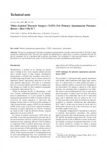
Coronary vein images in four healthy adult subjects acquired with MT-GRE. In subject a) there is no lateral vein branch available while volunteer b) has a favorable lateral vein. Volunteers c) and d) both have a lateral vein but with an acute take off angle which could cause difficulty in lead placement. We found that a lateral view such as the ones here are the preferred view for our EP colleagues who are the end-user of these images. Contrast enhanced coronary vein imaging has been studied by a number of groups, e.g. the group in Ulm with an intravascular contrast agent [25], Berlin [26] and Leeds [27]
CS
GCV LV
MCV
Images of the coronary sinus and lateral veins of four healthy volunteers, acquired using an experimental intrasvascular contrast agent.
Koninklijke Philips Electronics N.V. 2011
11
PR-TN 2011/00132
Unclassified
Assessment of dyssynchrony A key element in CRT is the quantification of dyssynchrony. Here, the gold standard is still ultrasound but the conclusion of the PROSPECT study [28] was “no single echocardiographic measure of dyssynchrony may be recommended to improve patient selection for CRT beyond current guidelines”. The superior image quality of MR compared with US and the lack of sensitivity to operator dependence make it a particularly interesting modality for assessing dyssynchrony. There is one drawback, however: there are so many different imaging methods. With tagging, at the start of the cardiac cycle, an MRI visible pattern is imprinted in the cardiac muscle which is followed over the entire cycle, allowing the quantitative determination of heart motion [29]. Variants that directly measure strain are SENC [30] and DENSE [31] and the myocardial motion can also be assessed with tissue phase mapping (TPM) [32] in which the myocardial velocity is directly encoded by the application of bipolar gradients causing the spins to acquire a phase that is directly proportional to their velocity. Since the direction of the velocity encoding gradients can be chosen freely, TPM enables the quantitative assessment of the 3D flow vector. A relatively simple and attractive approach is the analysis of cine short axis images, and sophisticated contour tracking methods exist in commercial software for wall motion analysis. A similar analysis can be used to generate bulls-eye plots of the location of, for example, the maximum wall motion and the timing of the maximum wall motion.
The combination of MR-roadmaps for anatomy, coronary vein imaging, dyssynchrony assessment and scar visualization could become the definitive MR-only tool for CRT. MR-guided EP with MR-safe devices The ultimate goal of MRI in the EP lab is the performance of the complete procedure under MR guidance. Several groups are working towards this goal. The Johns Hopkins group has performed a diagnostic EP study in the right atrium using real-time MRI in dogs as well as two patients [33]. The MGH group has used catheter tracking and 3D roadmaps to perform diagnostic EP studies in the left ventricle in pigs [34]. While in Würzburg, the focus has been on using carbon-based safe catheters in a diagnostic study in pigs [35] and the Eppendorf group has shown an ablation of the cavotricuspid isthmus in pigs guided by real-time MRI [36]. The Utah group recently published MRI-guided ablation in left and right atria of pigs including lesion visualization [37]. The advantages of MRI guided EP include the excellent 3D anatomical and functional represen12
Koninklijke Philips Electronics N.V. 2011
Unclassified
PR-TN 2011/00132
tation of the heart, visualization of the catheter relative to the live cardiac anatomy, the intraprocedural feedback on lesion completeness, infarct imaging, being able to check for collateral damage like atria-esophageal fistulas or pericardial effusion [32 (convert to symbolic link)] and, of course, the lack of ionizing radiation. A particular challenge in interventional MRI has always been the safety of the devices, in particular the risk of heating of long conducting wires in catheters. The safe transmission line published in 2005 by Weiss et al [38][39] solves this problem by effectively cutting the wire into smaller pieces and connecting the pieces with miniature transformers. This solution is effectively applied to the tracking coil carrying high frequency signals. The requirements for EP sensing and pacing, however, are different: the frequency content is much lower and it has been shown that highly resistive wires with a resistance in the order of a kilohm effectively dampen resonances. RF ablation, therefore, requires another approach. This task requires much higher powers that cannot be delivered via transformer cables or highly resistive wires. Instead, a switched cable is used. The concept is similar to the transmission line. The default position of the switches is open, leading to a safe configuration of short wires. Only during ablation are the switches closed, making one long conducting wire capable of delivering the RF ablation energy. The scanner will not apply RF or only very low SAR tracking sequences during closing of the switches. So together with temperature measurements and impedance measurements, we now have all EP functionality in one MR-safe catheter [40].
Summary in pictures of the work performed at Philips research on the development of a MR-safe EP catheter.
Koninklijke Philips Electronics N.V. 2011
13
PR-TN 2011/00132
Unclassified
MR-guided EP- navigation The main components in a MR-EP suite are the MR scanner, the EP catheters, the EP recorder and pacer and the RF amplifier. We decided upon one control center, the MR-EP navigation prototype. This workstation is based on the existing Philips EP-Navigator and combines the input from the EP recorder and the MRI scanner in one comprehensive user interface. It also drives the MRI-scanner using the XTC-interface [41].
Overview of required devices and software in an interventional MRI-EP suite. The MR-EP navigation prototype guides the operator through the procedure workstep by workstep as electrophysiologists are used to this approach from the EP-Navigator product. In a first step, a 3D balanced FFE scan is performed to serve as a 3D roadmap. The heart is then automatically segmented using the integrated Philips Smartheart MR software.
We also envision including segmentation of the myocardium or measures as described above to provide wall thickness information. Furthermore, LGE scans may be used to visualize scar tissue in redo procedures. These roadmaps are used in a separate planning step to define useful geometries for the later intervention and as underlays for catheter tracking experiments. The operator has the choice of using roadmap imaging with high temporal resolution catheter tracking or real-time imaging. In addition, the connection with an EP-recorder allows the physician to generate EP activation maps. This setup is currently used in a pre-clinical study in pigs performed by King’s College London and Philips Research [42].
14
Koninklijke Philips Electronics N.V. 2011
Unclassified
PR-TN 2011/00132
Screengrabs of the MR-EP navigation prototype which is used in a pre-clinical trial to study the efficacy of MRI-guided EP interventions.
Koninklijke Philips Electronics N.V. 2011
15
PR-TN 2011/00132
Unclassified
References [1] M. Haïssaguerre e.a., “Spontaneous initiation of atrial fibrillation by ectopic beats originating in the pulmonary veins”, The New England Journal of Medicine, vol. 339, nr. 10, pp. 659-666, sep. 1998. [2] J. Ector e.a., “Cardiac three-dimensional magnetic resonance imaging and fluoroscopy merging: a new approach for electroanatomic mapping to assist catheter ablation”, Circulation, vol. 112, nr. 24, pp. 3769-3776, dec. 2005. [3] S. Knecht e.a., “Computed tomography–fluoroscopy overlay evaluation during catheter ablation of left atrial arrhythmia”, Europace, vol. 10, nr. 8, pp. 931 -938, 2008. [4] M. V. Orlov e.a., “First experience with rotational angiography of the right ventricle to guide ventricular tachycardia ablation”, Heart Rhythm, vol. 8, nr. 2, pp. 207-211, 2011. [5] S. G. Duckett e.a., “Advanced image fusion to overlay coronary sinus anatomy with real-time fluoroscopy to facilitate left ventricular lead implantation in CRT”, Pacing and Clinical Electrophysiology: PACE, vol. 34, nr. 2, pp. 226-234, feb. 2011. [6] C. Meyer e.a., “Automatic intra-operative generation of geometric left atrium/pulmonary vein models from rotational X-ray angiography”, Medical Image Computing and Computer-Assisted Intervention: MICCAI ... International Conference on Medical Image Computing and Computer-Assisted Intervention, vol. 11, nr. 2, pp. 61-69, 2008. [7] T. H. Hauser, S. McClennen, G. Katsimaglis, M. E. Josephson, W. J. Manning, en S. B. Yeon, “Assessment of left atrial volume by contrast enhanced magnetic resonance angiography”, Journal of Cardiovascular Magnetic Resonance: Official Journal of the Society for Cardiovascular Magnetic Resonance, vol. 6, nr. 2, pp. 491-497, 2004. [8] W. A. Willinek e.a., “Randomly segmented central k-space ordering in high-spatial-resolution contrast-enhanced MR angiography of the supraaortic arteries: initial experience”, Radiology, vol. 225, nr. 2, pp. 583-588, nov. 2002. [9] W. A. Willinek e.a., “4D time-resolved MR angiography with keyhole (4D-TRAK): more than 60 times accelerated MRA using a combination of CENTRA, keyhole, and SENSE at 3.0T”, Journal of Magnetic Resonance Imaging: JMRI, vol. 27, nr. 6, pp. 1455-1460, jun. 2008. [10] C. Juli, “Left Atrial Imaging Cookbook”. 03-mrt-2011. [11] P. Koken e.a., “Atrial Thickness Mapping for EP Ablation using Black-Blood Restricted Field of View MRI”, ISMRM 2011, vol. 3734. [12] O. K. Mohrs e.a., “Thrombus detection in the left atrial appendage using contrast-enhanced MRI: a pilot study”, AJR. American Journal of Roentgenology, vol. 186, nr. 1, pp. 198-205, jan. 2006. [13] E. Spuentrup e.a., “MR imaging of thrombi using EP-2104R, a fibrin-specific contrast agent: initial results in patients”, European Radiology, vol. 18, nr. 9, pp. 1995-2005, sep. 2008. [14] D. C. Peters e.a., “Detection of pulmonary vein and left atrial scar after catheter ablation with three-dimensional navigator-gated delayed enhancement MR imaging: initial experience”, Radiology, vol. 243, nr. 3, pp. 690-695, jun. 2007. [15] B. R. Knowles e.a., “3-D visualization of acute RF ablation lesions using MRI for the simultaneous determination of the patterns of necrosis and edema”, IEEE Transactions on Bio-Medical Engineering, vol. 57, nr. 6, pp. 1467-1475, jun. 2010. [16] J. Meng e.a., “Late gadolinium enhancement of the esophagus is common on cardiac MR several months after pulmonary vein isolation: preliminary observations”, Pacing and Clinical Electrophysiology: PACE, vol. 33, nr. 6, pp. 661-666, jun. 2010. [17] S. D. Roes e.a., “Infarct tissue heterogeneity assessed with contrast-enhanced MRI predicts spontaneous ventricular arrhythmia in patients with ischemic cardiomyopathy and implantable cardioverterdefibrillator”, Circulation. Cardiovascular Imaging, vol. 2, nr. 3, pp. 183-190, mei. 2009. [18] E. Perez-David e.a., “Noninvasive identification of ventricular tachycardia-related conducting channels using contrast-enhanced magnetic resonance imaging in patients with chronic myocardial infarction: comparison of signal intensity scar mapping and endocardial voltage mapping”, Journal of the American College of Cardiology, vol. 57, nr. 2, pp. 184-194, jan. 2011. [19] C. P. Naehle e.a., “Magnetic resonance imaging at 1.5-T in patients with implantable cardioverter16
Koninklijke Philips Electronics N.V. 2011
Unclassified
PR-TN 2011/00132
defibrillators”, Journal of the American College of Cardiology, vol. 54, nr. 6, pp. 549-555, aug. 2009. [20] R. Sutton e.a., “Safety of magnetic resonance imaging of patients with a new Medtronic EnRhythm MRI SureScan pacing system: clinical study design”, Trials, vol. 9, p. 68, 2008. [21] W. Y. Kim e.a., “Coronary magnetic resonance angiography for the detection of coronary stenoses”, The New England Journal of Medicine, vol. 345, nr. 26, pp. 1863-1869, dec. 2001. [22] R. Nezafat e.a., “Coronary magnetic resonance vein imaging: imaging contrast, sequence, and timing”, Magnetic Resonance in Medicine: Official Journal of the Society of Magnetic Resonance in Medicine / Society of Magnetic Resonance in Medicine, vol. 58, nr. 6, pp. 1196-1206, dec. 2007. [23] C. T. Stoeck e.a., “Whole heart magnetization-prepared steady-state free precession coronary vein MRI”, Journal of Magnetic Resonance Imaging: JMRI, vol. 29, nr. 6, pp. 1293-1299, jun. 2009. [24] C. T. Stoeck e.a., “Optimization of on-resonant magnetization transfer contrast in coronary vein MRI”, Magnetic Resonance in Medicine: Official Journal of the Society of Magnetic Resonance in Medicine / Society of Magnetic Resonance in Medicine, vol. 64, nr. 6, pp. 1849-1854, dec. 2010. [25] V. Rasche e.a., “Whole-heart coronary vein imaging: a comparison between non-contrast-agentand contrast-agent-enhanced visualization of the coronary venous system”, Magnetic Resonance in Medicine: Official Journal of the Society of Magnetic Resonance in Medicine / Society of Magnetic Resonance in Medicine, vol. 57, nr. 6, pp. 1019-1026, jun. 2007. [26] A. Chiribiri e.a., “Visualization of the cardiac venous system using cardiac magnetic resonance”, The American Journal of Cardiology, vol. 101, nr. 3, pp. 407-412, feb. 2008. [27] J. F. Younger, S. Plein, A. Crean, S. G. Ball, en J. P. Greenwood, “Visualization of coronary venous anatomy by cardiovascular magnetic resonance”, Journal of Cardiovascular Magnetic Resonance: Official Journal of the Society for Cardiovascular Magnetic Resonance, vol. 11, p. 26, 2009. [28] E. S. Chung e.a., “Results of the Predictors of Response to CRT (PROSPECT) trial”, Circulation, vol. 117, nr. 20, pp. 2608-2616, mei. 2008. [29] A. K. Rutz, R. Manka, S. Kozerke, S. Roas, P. Boesiger, en J. Schwitter, “Left ventricular dyssynchrony in patients with left bundle branch block and patients after myocardial infarction: integration of mechanics and viability by cardiac magnetic resonance”, European Heart Journal, vol. 30, nr. 17, pp. 21172127, sep. 2009. [30] A. Hamdan e.a., “Strain-encoded MRI to evaluate normal left ventricular function and timing of contraction at 3.0 Tesla”, Journal of Magnetic Resonance Imaging: JMRI, vol. 29, nr. 4, pp. 799-808, apr. 2009. [31] A. H. Aletras, S. Ding, R. S. Balaban, en H. Wen, “DENSE: displacement encoding with stimulated echoes in cardiac functional MRI”, Journal of Magnetic Resonance (San Diego, Calif.: 1997), vol. 137, nr. 1, pp. 247-252, mrt. 1999. [32] A. Lutz, A. Bornstedt, R. Manzke, P. Etyngier, G. U. Nienhaus, en V. Rasche, “Acceleration of tissue phase mapping by k-t BLAST: a detailed analysis of the influence of k-t-BLAST for the quantification of myocardial motion at 3T”, Journal of Cardiovascular Magnetic Resonance: Official Journal of the Society for Cardiovascular Magnetic Resonance, vol. 13, p. 5, 2011. [33] S. Nazarian e.a., “Feasibility of real-time magnetic resonance imaging for catheter guidance in electrophysiology studies”, Circulation, vol. 118, nr. 3, pp. 223-229, jul. 2008. [34] S. R. Dukkipati e.a., “Electroanatomic mapping of the left ventricle in a porcine model of chronic myocardial infarction with magnetic resonance-based catheter tracking”, Circulation, vol. 118, nr. 8, pp. 853-862, aug. 2008. [35] P. Nordbeck e.a., “Feasibility of real-time MRI with a novel carbon catheter for interventional electrophysiology”, Circulation. Arrhythmia and Electrophysiology, vol. 2, nr. 3, pp. 258-267, jun. 2009. [36] B. A. Hoffmann e.a., “Interactive real-time mapping and catheter ablation of the cavotricuspid isthmus guided by magnetic resonance imaging in a porcine model”, European Heart Journal, vol. 31, nr. 4, pp. 450-456, feb. 2010. [37] G. R. Vergara e.a., “Real-time magnetic resonance imaging-guided radiofrequency atrial ablation and visualization of lesion formation at 3 Tesla”, Heart Rhythm: The Official Journal of the Heart Rhythm Society, vol. 8, nr. 2, pp. 295-303, feb. 2011. [38] P. Vernickel, V. Schulz, S. Weiss, en B. Gleich, “A safe transmission line for MRI”, IEEE Transactions
Koninklijke Philips Electronics N.V. 2011
17
PR-TN 2011/00132
Unclassified
on Bio-Medical Engineering, vol. 52, nr. 6, pp. 1094-1102, jun. 2005. [39] S. Weiss, P. Vernickel, T. Schaeffter, V. Schulz, en B. Gleich, “Transmission line for improved RF safety of interventional devices”, Magnetic Resonance in Medicine: Official Journal of the Society of Magnetic Resonance in Medicine / Society of Magnetic Resonance in Medicine, vol. 54, nr. 1, pp. 182-189, jul. 2005. [40] S. Weiss e.a., “In vivo evaluation and proof of radiofrequency safety of a novel diagnostic MRelectrophysiology catheter”, Magnetic Resonance in Medicine: Official Journal of the Society of Magnetic Resonance in Medicine / Society of Magnetic Resonance in Medicine, vol. 65, nr. 3, pp. 770-777, mrt. 2011. [41] J. Smink e.a., “eXTernal Control (XTC): a flexible, real-time, low-latency, bi-directional scanner interface”, ISMRM 2011, vol. 1755. [42] S. Krueger e.a., “Preclinical evaluation of an MR-EP suite including an MR-EP navigator and dedicated MR-EP catheters”, ISMRM 2010, vol. 284.
18
Koninklijke Philips Electronics N.V. 2011
Unclassified
Koninklijke Philips Electronics N.V. 2011
PR-TN 2011/00132
19