this work, Stitt shows that binary synthesis can be used to transparently incorporate hardware design tools into established software tool flows. In this approach ...
Techniques for Synthesizing Binaries to an Advanced Register/Memory Structure Greg Stitt, Zhi Guo, Frank Vahid*, Walid Najjar Department of Computer Science and Engineering University of California, Riverside { gstitt, zguo, vahid, najjar }@cs.ucr.edu http://www.cs.ucr.edu/~{ gstitt, zguo, vahid, najjar } *Also with the Center for Embedded Computer Systems, UC Irvine
ABSTRACT Recent works demonstrate several benefits of synthesizing software binaries onto FPGA hardware, including incorporating hardware design into established software tool flows with minimal impact, porting existing binaries to FPGAs, and even dynamically synthesizing software kernels to faster FPGA coprocessors. Those works showed that standard binary decompilation methods can recover enough high-level control information to result in reasonably-efficient hardware. However, recent synthesis methods for FPGAs utilize advanced memory structures, such as a "smart buffer," that require recovery of additional high-level information, specifically information about loops and arrays. We incorporate decompilation techniques into an existing binary synthesis tool flow to recover loops and arrays in order to take advantage of advanced memory structures when performing synthesis from a binary. We demonstrate through experiments on six benchmarks that our methods improve binary synthesis performance by 53%, by making effective use of smart buffers. Furthermore, we compare the binary results using smart buffers with results of synthesis directly from the original C code for the benchmarks, and show that our methods achieved almost identical performance results with only 10% area overhead.
Categories and Subdescriptors C.3 [Special-Purpose and Application-Based Systems]: Realtime and embedded systems.
General Terms Performance, Design.
Keywords Decompilation, FPGA, synthesis, smart buffers, embedded systems, binaries.
1. INTRODUCTION Recent work has shown that synthesis of hardware from software binaries can be advantageous in several situations. Stitt et al. initially introduced the synthesis of software binaries in [16]. In this work, Stitt shows that binary synthesis can be used to Permission to make digital or hard copies of all or part of this work for personal or classroom use is granted without fee provided that copies are not made or distributed for profit or commercial advantage and that copies bear this notice and the full citation on the first page. To copy otherwise, or republish, to post on servers or to redistribute to lists, requires prior specific permission and/or a fee. FPGA’05, February 20–22, 2005, Monterey, California, USA. Copyright 2005 ACM 1-59593-029-9/05/0002...$5.00.
transparently incorporate hardware design tools into established software tool flows. In this approach, binary synthesis generates hardware from a software description written in any language, possibly even multiple languages, after being compiled into a software binary by any compiler. The FREEDOM compiler [13] illustrates another use of synthesis from binaries, namely that of porting existing or legacy DSP binaries into custom FPGA hardware, utilizing the parallelism of hardware to achieve improved performance compared to the software execution of the binary. Critical Blue [6] uses a similar binary-level approach, creating a custom VLIW coprocessor from a binary to speedup the software execution of critical loops and other frequent regions of an application. More recently, Warp processors [11][14] have synthesized software binaries dynamically in order to partition a software application onto a custom configurable logic fabric at runtime. Such dynamic partitioning transparently improves the performance of the application as the application executes, thus requiring no designer effort. Warp processors can also potentially take advantage of frequent data values and phase information to perform optimizations that would normally not be possible in a static partitioning approach without detailed profiling information. Previous approaches to synthesis from a software binary have achieved reasonably well-performing hardware. However, none of the previous efforts have synthesized advanced register or memory structures that support data reuse, such as smart buffers [7], which are used by high-level synthesis approaches. Highlevel synthesis tools typically analyze loops, arrays, and alias information to determine reused memory data, and then store reused data in smart buffers, essentially reducing memory access time while increasing bandwidth. Synthesis tools for software binaries have no knowledge of loops, arrays, or memory access patterns and therefore cannot synthesize smart buffers, resulting in hardware that is much slower than would be synthesized by a high-level synthesis tool. In this paper, we show that binary synthesis approaches can utilize smart buffers by first using decompilation techniques to recover necessary high-level information. Previous binary synthesis approaches have used a limited form of decompilation to remove overhead from the binary, so that the binary is more appropriate for hardware implementation. However, the decompilation techniques we use recover additional high-level information and convert the software binary into a higher-level language that can be used as input to a high-level synthesis tool, or alternatively can annotate the binary with high-level information so that a binary synthesis tool can determine potential data reuse. We apply existing decompilation techniques to recover control structures, to recover arrays, and to remove instruction-set overhead. After
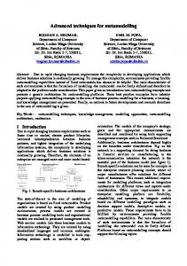
Figure 1: Data reuse using smart buffers for a FIR filter. a) Code for a FIR filter. (b) Windows for each loop iteration and the state of the smart buffer after each iteration. Void fir() { for (int i=0; i < 50; i ++) {
Smart buffer after 1st iteration
B[i] = C0 * A[i] + C1 *A[i+1] + C2 * A[i+2] + C3 * A[i+3];
A[0]
A[1]
A[2]
A[3]
} } a) Smart buffer after 2nd iteration 1st iteration window
A[0]
A[1]
A[2]
A[3]
A[4]
2nd iteration window Smart buffer after 3rd iteration A[0] A[1] A[2] A[3] A[4] A[5] A[6] A[7] A[8] …. …………………
b)
3rd iteration window
decompiling to recover high-level information that enables the use of smart buffers, we show a 53% performance improvement over binary synthesis approaches that perform a more limited form of decompilation. We also compare the synthesis of binaries after decompilation to the synthesis from the original C code, showing almost no performance difference and an average area overhead of 10% for binary synthesis. Our comparison to C is meant to show that there is not much more optimization that can be achieved at the binary level after using decompilation, because the synthesis from C should always be better or equivalent to synthesis from a binary. Although the results we achieved were similar on several examples for both synthesis from a binary and synthesis from C, in the general case, synthesis from C should produce superior results.
2. ADVANCED REGISTER/MEMORY STRUCTURES – SMART BUFFERS Hardware performance is commonly limited by memory bandwidth. Frequently, optimizations that could potentially provide large amounts of parallelism, such as loop unrolling, have limited benefits because the memory bandwidth of the system cannot provide data at a fast enough rate. For example, consider the FIR filter shown in Figure 1(a). In this example, each iteration of the loop reads four values from memory. Assuming that memory width is the same size as each array element, this code would require four memory reads per iteration and would limit the amount of parallelism to only one multiplication at a time. Ideally, we would want to unroll the loop and perform several iterations in parallel. However, to perform four iterations in parallel, we would have to be able to fetch 16 memory locations simultaneously, which would require 16 times more memory bandwidth.
A[0]
A[1]
A[2]
A[3]
A[4]
A[5]
* new data is shown in bold
Data reuse helps eliminate memory bandwidth problems by reducing the need to refetch data that the datapath will use again. Many algorithms that designers consider for hardware implementation are well suited for data reuse due to the frequent use of window operations. A window is a region of memory consisting of sequential locations, possibly in multiple dimensions. Generally, the windows used in consecutive loop iterations overlap with the windows used in previous iterations. The overlapping window regions signify data that the hardware will reuse and in the ideal situation the hardware would only fetch data from these locations one time. Typically, a designer determines the amount of possible data reuse, possibly by transforming the code, and creates a custom memory structure to store reused data. Ideally, a synthesis tool would be able to automatically detect reused data and keep this data stored in a smart buffer [7]. A smart buffer is a small memory or register structure that stores the required memory window for a region of code, which is usually a loop. When loading data for a new window, the smart buffer only removes regions that will not be reused in future windows. Using smart buffers can greatly reduce the amount of data fetched from memory, essentially increasing memory bandwidth and reducing average access time. To use smart buffers for a loop, a synthesis tool must be able to determine the window of each iteration of the loop. A synthesis tool typically determines the window for each loop iteration by analyzing the use of loop induction variables in array accesses. In addition to determining the window for each iteration, the synthesis tool must also determine the stride of the window after each iteration and the loop bounds, both of which are also determined by analyzing the use of loop induction variables in the code. After obtaining information on the size of windows and how the windows change for each iteration, the
Figure 2: Typical architecture for smart buffers. Input Address Generator
RAM
Software Binary Binary Parsing
Smart Buffer
Controller
Figure 3: Decompilation of software binaries.
Datapath
Register Transfer Lists CDFG Creation Control Structure Recovery Data Structure Recovery
Smart Buffer Output Address Generator
Instruction-Set Overhead Removal RAM
synthesis tool can determine the amount of overlap between windows. The synthesis tool can then create a smart buffer that only fetches data for non-overlapping window regions. Figure 1(b) shows the windows for each iteration of the FIR filter example in Figure 1(a) and the corresponding smart buffer state at each iteration. In the first iteration, the smart buffer fetches the first four array elements that make up the first window. The window of the second iteration contains three elements (A[1], A[2], and A[3]) from the window of the first iteration. In this case, the smart buffer only fetches a single element (A[4]). Each subsequent iteration follows a similar pattern, sharing three elements with the previous iteration. For this example, a smart buffer saves three memory accesses per iteration, excluding the first iteration that requires four memory accesses. Figure 2 illustrates a typical architecture that utilizes smart buffers. The controller controls the timing of operations in the datapath and address generators. The input address generator uses the window information determined by the synthesis tool to read non-overlapping window regions from RAM, which the smart buffer stores and combines with previous data to form a complete window. When the smart buffer has received a complete window, the smart buffer outputs the window to the datapath. In addition to the smart buffer that provides input to the datapath, the example architecture uses an additional smart buffer to store output from the datapath.
3. DECOMPILATION The synthesis techniques for smart buffers, discussed in Section 2, are based on the analysis of memory access patterns, obtained through loop structures, induction variables, and arrays. Synthesis tools that use a software binary as input have no knowledge of loops and arrays and therefore cannot determine memory access patterns that are needed to synthesize smart buffers. To recover loops and arrays, in additional to other useful high-level information, we must first perform decompilation. If decompilation is able to recover the original high-level code written by a designer, then high-level synthesis and synthesis from a software binary are able to create equivalent hardware. Of course, recovering the exact high-level source is generally impossible. However, we show in the following sections that
Decompiled C Code decompilation commonly recovers a very similar high-level representation, especially for code that is appropriate for hardware implementation. Decompilation also removes overhead that is introduced by the instruction-set architecture used by the binary, so that the binary is much more suitable for hardware synthesis. Note that the combination of binary synthesis and decompilation is not intended to replace high-level synthesis. Instead, we claim that integrating decompilation techniques into existing binary synthesis tools will introduce the capability for these binary tools to synthesize advanced memory structures, such as smart buffers. A decompiler used with binary synthesis can output a highlevel representation of a program in several formats. Many synthesis tools [1][7] use a control/data flow graph as input. The decompiler could therefore create a control/data flow graph for the software binary and annotate the control/data flow graph with high-level information denoting loops, arrays, etc. An alternative would be to output the decompiled representation into a highlevel language such as C and then use a high-level synthesis tool to synthesize the recovered code into hardware. Our decompilation tool flow is shown in Figure 3. Most of our decompilation techniques are based on work done by Cifuentes [3][4][5]. We use our own techniques to recover arrays and remove assembly overhead. Initially, Binary Parsing converts the binary into an intermediate representation that is independent of the instruction set used by the binary. CDFG Creation analyzes the intermediate format representation of the application and creates a control/data flow graph that is equivalent to the behavior of the binary. Next, Control Structure Recovery analyzes the control/data flow graph and recovers loops and if statements. Data Structure Recovery is responsible for recovering arrays. After recovering the high-level constructs, Instruction-Set Overhead Removal performs optimizations to remove the overhead introduced by the instruction set and assembly code. We have implemented a decompiler that implements all of the techniques shown in Figure 3. The input to our decompiler is a software binary compiled for the SimpleScalar [2] processor. The output of the decompiler is C code.
3.1 Binary Parsing Binary parsing is responsible for converting the machine dependent software binary into a machine independent representation. Using a machine independent representation
allows the same decompilation process to be used regardless of the instruction set architecture. The representation we use is register transfer lists [5]. A register transfer is an expression that defines a particular register or memory location. When converting assembly instructions to register transfers, we specify each register transfer by a semantic string corresponding to the semantics of the instruction. During binary parsing, we make instruction side effects explicit by creating a register transfer for each implicit operation. For example, a pop instruction would use two register transfers: one register transfer for the load and one register transfer for the stack pointer update.
3.2 CDFG Creation To create a control flow graph for the application, we first analyze jumps in the register transfer lists to determine basic blocks. After determining basic blocks, we construct a complete control flow graph by using the targets of the jumps to connect the basic blocks. A limitation of decompilation is the inability to eliminate indirect jumps. An indirect jump is a jump whose target is specified by the value of a register. Because the target isn’t known until runtime, we cannot statically create a control flow graph. In some cases, we can eliminate indirect jumps through definition-use analysis by determining all possible targets of the jump. Although the inability to deal with indirect jumps may seem like a major limitation, in reality only a small number of applications in reconfigurable systems utilize indirect jumps. We have analyzed examples from several benchmark suites and found that less than 5% of all examples use indirect jumps. We construct a data flow graph by analyzing the semantic strings for each register transfer. Each register transfer expression represents a subtree of the data flow graph for the block that the register transfer appears in. By parsing the semantic strings of each register transfer, we can create the subtree for each register transfer. We then use definition-use and use-definition analysis to connect the subtrees rooted at each register transfer into a complete data flow graph.
3.3 Control Structure Recovery Control structure recovery analyzes the CDFG to determine highlevel control structures such as loops and if statements. We recover loop structures using interval analysis [3]. An interval contains a maximum of one loop, which must start at the head of the interval. After checking all the intervals of a control flow graph for loops, each interval is collapsed into a single node, forming a new control flow graph, which we then check for additional loops. We repeat this process until the control flow graph can no longer be reduced. By processing loops in this order, we can determine the proper nesting order of loops. After finding a loop, we determine the type of the loop as pre-tested, post-tested, and endless based on the location of the exit from the loop. We also determine multi-exit loops that contain exits from the loop body. We determine loop induction variables through data and control flow analysis. Once we determine loop induction variables, we can determine the loop bounds by analyzing the exit condition of the loop and the update operation of the loop induction variable. Determining loop bounds is important for unrolling the loops during synthesis. For brevity, we omit a description of determining if statements. Cifuentes gives a complete description of the determination of if statements in [3].
3.4 Data Structure Recovery We perform data flow analysis to recover array data structures. We discover arrays by searching the control/data flow graph for memory accesses that have a linear access pattern. If such memory accesses are found, we assume they correspond to array accesses. Although we could try and detect other access patterns, generally only linear memory accesses can be implemented efficiently in hardware. We initially search the portions of the control/data flow graph that correspond to loops, because array accesses typically occur within loops, unless a loop has been unrolled by the software compiler. We determine the size of each array by using the bounds for each loop. Note that the size of the decompiled array might not correspond exactly to the size of the array in the original source code. An incorrect array size is generally determined only when a subset of an array is accessed in a loop. When an incorrect array size is recovered, the decompiled program is still equivalent to the original program, but the original array may be divided into multiple smaller arrays in the decompiled code. Once we have detected arrays within all loops, we try to map memory accesses not contained within loops onto existing arrays. If we cannot find an appropriate array for a memory access outside of an array, we either create a new array or a single memory location to handle the memory access. Detecting multidimensional array accesses is slightly more difficult, due to the requirement of detecting row-major ordering calculations in nested loops. The size of each dimension for a multidimensional array is determined using the bounds of each nested loop. If a loop is unbounded, or the bounds cannot be determined, then we cannot recover the size of the array. Once we have determined all row-major ordering calculations, we replace the calculations with simple indices into the multidimensional array. Due to the fact that compilers can implement arrays in assembly in a variety of ways, we cannot guarantee that all arrays will be recovered. However, from our experiments so far we have recovered 100% of all array structures for examples with bounded loops.
3.5 Instruction Set/Assembly Overhead Removal Compilers perform instruction selection based on the semantics of the program being compiled. Generally, a compiler is not concerned with the architectural resources being used. For example, compilers commonly implement a move operation with an arithmetic instruction using an immediate value of zero. This type of instruction selection can greatly increase the size of the data flow graph and can lead to inefficient hardware. Our decompilation process removes this overhead so that synthesis will be more successful. An additional type of instruction-set overhead that commonly occurs is compare-with-zero instructions. To compare two values using a compare-with-zero instruction, a compiler will typically subtract the two values and place the result in a temporary register. This temporary register is then used by the comparewith-zero instruction to determine the result of the comparison. If this compare-with-zero is not optimized away, then unnecessary subtractors will be synthesized. These subtractors can waste a huge amount of area, especially if the operations are 32-bit. One of the largest assembly overheads is caused by the fact that most instruction set architectures use operations that are implicitly 32-bit. The actual required size of the operation can be much
less. Determining the actual size of operations is extremely important, especially in the case of multiplication, which requires large amounts of hardware area. We recover the actual operation sizes by propagating size information given from load instructions. Instruction sets generally have load word, load half, and load byte instructions that load 4 bytes, 2 bytes, and 1 byte respectively. By propagating this size information over an entire data flow graph, we can reduce the size of each operation to the maximum size of all the inputs to the operation. Stack operations also cause overhead that the decompilation process must remove. Compilers use these stack operations to handle parameter passing and register spills. When synthesized to hardware, stack operations create excess accesses to main memory, which can greatly limit parallelism. A compiler will generally use stack operations due to a small limit on the number of registers in the microprocessor architecture. When we synthesize hardware for the application, the limit on the number of registers no longer applies. Therefore, stack operations can be removed by replacing each stack operation with an access to an additional register. Of course, we cannot remove stack operations from recursive functions. The inability to deal with recursive functions is not a drawback because recursion cannot be implemented efficiently in hardware.
3.6 Limitations In some cases, the decompilation of arbitrary binaries has been shown to be impossible [4]. As previously mentioned, decompilation usually fails for regions of a binary that contain indirect jumps. Also, most decompilation techniques assume that the assembly code is written in a way such that control flow does not jump between functions, except by using call and return primitives. Although most compilers will never compile code that jumps between functions, a designer could perform this type of operation when hand optimizing the assembly code. Fortunately, these limitations do not usually affect the decompilation of application binaries for embedded and reconfigurable systems. Code for embedded systems and reconfigurable systems generally does not contain constructs that can be problematic for decompilers, such as pointers, switch statements, virtual functions, etc. In previous work [15], we have decompiled several dozen benchmarks from the EEMBC, MediaBench, and NetBench benchmarks suites, successfully recovering a similar high-level representation of the examples over 90% of the time. This high success rate suggests that although decompilation may not always be beneficial for binary synthesis, the success rate is high enough to justify integrating decompilation techniques into a binary synthesis approach.
4. EXPERIMENTS 4.1 Experimental Setup We are currently using six benchmarks in our experiments. Bit_Correlator counts the number of bits in an 8-bit integer that match a constant mask. Fir is a 5-tap finite-impulse-response filter. Udiv8 is an 8-bit divider. Prewitt implements the Prewitt edge-detection algorithm. Mf9 is a moving average filter that approximates the average of nine samples. The Moravec example implements a specific kernel of the Moravec algorithm. The input vectors consist of 256 element arrays, except for Prewitt and Moravec, which use a 2-dimensional 256x256 array. We are currently working on synthesizing examples from the EEMBC
and MediaBench suites, but the results were not available at the time of this publication. We used the high-level synthesis tool, ROCCC [7], to synthesize hardware with smart buffers. ROCCC takes highlevel language code, such as C, as input and generates RTL (register transfer level) VHDL for reconfigurable devices. ROCCC is built on the SUIF2 [17] and Machine-SUIF [12] platforms. SUIF provides high-level information about loops and memory accesses, which ROCCC uses to perform loop level analysis and optimizations. Most of the information needed to design high-level components, such as controllers and address generators is extracted by ROCCC from SUIF code. MachineSUIF is an infrastructure for constructing the back-end of a compiler, which provides libraries such as the Control Flow Graph library [8], Data Flow Analysis library [9], and Static Single Assignment library [10] that can be used for optimization and analysis. The ROCCC synthesis tool modifies SUIF2 and Machine-SUIF, adding new analysis and optimization techniques. ROCCC relies on the commercial tool Xilinx ISE to synthesize the RTL VHDL code into a netlist. The target architecture of all synthesis is the Xilinx XC2V2000 FPGA.
4.2 Comparison of Synthesis From a Binary With and Without Smart Buffers In this section, we present results illustrating the performance of hardware synthesized from a software binary, both with and without the smart buffers that are made possible using the decompilation techniques described in Section 3. For all examples, we generated a binary by compiling the C code for the examples using a version of gcc ported to the SimpleScalar PISA instruction set. We compiled all examples using a low level of optimization effort (-O1). For the experiments with smart buffers, we generated hardware by decompiling the binaries using our own decompilation tools into a C code representation that could be compiled using ROCCC. We could have instead implemented the synthesis of smart buffers into an existing binary synthesis tool without having to decompile to C, but we found that using ROCCC was a simpler solution. For the results without smart buffers, we estimate performance using the same datapath given from ROCCC but without smart buffers and without any form of data reuse. Table 1 shows results comparing these two approaches. Cycles are the number of cycles required for the synthesized hardware to execute. Clock is the clock frequency obtained for the synthesized hardware after placement and routing for the Xilinx XC2V2000. Time is the execution time of the example when synthesized to hardware. %TimeImprovement is the percentage improvement in execution time when performing decompilation and using smart buffers. The results show that on average, the use of smart buffers results in a 53% performance increase. For two of the examples, there was no improvement in execution time. The reason for the identical performances is that ROCCC did not use smart buffers because of the lack of potential data reuse for these examples. The smart buffer in the fir example required 8 16-bit registers. The smart buffer in the Prewitt example required 36 16-bit registers. The mf9 smart buffer required 11 16-bit registers. The Moravec smart buffer used 15 16-bit registers.
Table 1: A comparison of hardware synthesized from a binary, both with and without smart buffers.
W/O Smart Buffers With Smart Buffers Example Cycles Clock Time Cycles Clock Time %TimeImprovement bit_correlator 258 118 2.2 258 118 2.2 0% fir 577 125 4.6 129 125 1.0 78% udiv8 281 190 1.5 281 190 1.5 0% prewitt 172086 123 1399.1 64516 123 524.5 63% 8194 57 143.0 258 57 4.5 97% mf9 moravec 969264 66 14663.6 195072 66 2951.2 80% 53% Avg: Table 2: A comparison of hardware synthesized from a binary and from original C code, both with smart buffers.
Synthesis from C Code Synthesis from Binary Example Cycles Clock Time Area Cycles Clock Time Area %TimeImprovement %AreaOverhead bit_correlator 258 118 2.19 15 258 118 2.19 15 0% 0% fir 129 125 1.03 359 129 125 1.03 371 0% 3% udiv8 281 190 1.48 398 281 190 1.48 398 0% 0% prewitt 64516 123 525 2690 64516 123 525 4250 0% 58% mf9 258 57 4.5 1048 258 57 4.5 1048 0% 0% moravec 195072 66 2951 680 195072 70 2791 676 -6% -1% -1% 10% Avg:
4.3 Comparison of Synthesis From a Binary With Smart Buffers and High-Level Synthesis With Smart Buffers In this section, we compare the performance of hardware using smart buffers when synthesized from both a software binary and from the original high-level C code, in order to determine how much more optimization is possible during binary synthesis after decompiling. Hardware generated during synthesis from C code should always be superior, or at least equivalent to, the hardware synthesized a binary. Therefore, if synthesis from a binary can achieve similar results to synthesis from C code, then there is likely little more optimization that can be achieved from a binary synthesis when performing decompilation. We used the same experimental setup as in Section 4.2 to obtain smart buffer hardware from a software binary. Table 2 compares the performances of the hardware when synthesizing from both a binary and C code. Cycles are the number of cycles required for the synthesized hardware to execute to completion. Clock is the clock frequency obtained for the synthesized hardware after placement and routing for the Xilinx XC2V2000. Time is the execution time of the example when synthesized to hardware. Area is the number of slices required by the datapath in the synthesized hardware. %TimeImprovement is the percentage improvement in execution time of hardware when performing synthesis from C, compared to hardware synthesized from a binary. %AreaOverhead is the area overhead of synthesis from a binary. The results show identical performances for both approaches on 5 of the examples. For the Moravec example, the hardware synthesized from the binary was actually faster than the hardware synthesized from C. The reason for this performance difference is that during software compilation, the software compiler applied several optimizations that transformed the code into a representation more suitable for synthesis, resulting in a slighter
higher clock frequency in the synthesized hardware. If ROCCC had performed these same optimizations, or if the binary would have been generated without optimizations, the performances would be identical. The negative area overhead for the Moravec example occurred for the same reason. Although synthesis from a binary outperforms synthesis from C code for this example, in the general case synthesis from C will achieve superior results. For the bit_correlator and udiv8 examples, the hardware that was synthesized was identical for both binary and high-level synthesis, due to the ability of decompilation to recover an almost exact replica of the original source code. The fir example had the same performance for both approaches but differed slightly in terms of area. The difference in area for fir was caused by the software compiler performing strength-reduction, which converted some of the multiplications into shift and add operations. These shift and add operations required additional pipeline stages and therefore increased the area. Prewitt achieved identical performance for both binary and high-level synthesis, but the hardware created from the binary required 58% more area. The reason for the area overhead was that the decompiler was unable to remove temporary registers from long expressions, which increased the size of the datapath. On average, there was a 10% increase in area for binary synthesis.
4.4 Future Work We are currently running these same experiments for software binaries generated with different compiler optimizations. Aggressive compiler optimizations could potentially obscure the software binary, making decompilation less successful at recovering high-level information. Also, optimizations such as loop unrolling could eliminate control instructions that decompilation techniques use to recover high-level loop structures. We plan on using loop rerolling, in addition to other techniques to overcome problems with compiler optimizations when synthesizing a software binary. For the results we have
obtained, decompilation has commonly recovered enough highlevel information to make binary synthesis competitive with synthesis from C code. We are also currently running the experiments in this paper on different instructions sets to determine if synthesis from a binary is possible on a variety of instruction set architectures. Although we do not yet have results, we estimate that there will be little difference between instruction sets because decompilation has successfully recovered high-level representations of these programs on several different instruction sets.
5. CONCLUSIONS Previous work has shown that the synthesis of software binaries can be beneficial in several situations. A disadvantage to previous binary synthesis approaches is that high-level information is lost during software compilation. Without this high-level information, efficient memory structures cannot be synthesized, resulting in reduced hardware performance compared to high-level synthesis. In this paper, we showed that by utilizing decompilation, binary synthesis can recover loops and arrays therefore enabling synthesis of the same memory structures that are commonly created in high-level synthesis approaches. When using decompilation, we show a 53% improvement in performance compared to a binary synthesis approach that does not use decompilation. We also presented results for six examples showing that when utilizing decompilation, the synthesis of software binaries can sometimes achieve identical performance compared to high-level synthesis. Binary synthesis had an area overhead of 10%.
6. ACKNOWLEDGEMENTS This research was supported in part by the National Science Foundation (CCR-0203829) and by the Semiconductor Research Corporation (2003-HJ-1046G).
7. REFERENCES [1]
[2]
K. Bondalapati, P. Diniz, P. Duncan, J. Granacki, M. Hall, R. Jain, and H. Ziegler. DEFACTO: A Design Environment for Adaptive Computing Technology. In Reconfigurable Architectures Workshop, RAW’99, April 1999. D. Burger and T.M. Austin. The SimpleScalar Tool Set, Version 2.0. University of Wisconsin-Madison Computer Sciences Department Technical Report #1342. June, 1997.
[3] [4]
[5]
[6] [7]
[8] [9] [10] [11] [12] [13]
[14] [15]
[16] [17]
C. Cifuentes. Structuring Decompiled Graphs. In Proceedings of the International Conference on Compiler Construction, volume 1060 of Lecture Notes in Computer Science, pg. 91-105. April 1996. C. Cifuentes, D. Simon, A. Fraboulet. Assembly to High-Level Language Translation. Department of Compter Science and Electrical Engineering, University of Queensland. Technical Report 439, August 1998. C. Cifuentes, M. Van Emmerik, D.Ung, D. Simon, T. Waddington. Preliminary Experiences with the Use of the UQBT Binary Translation Framework. Proceedings of the Workshop on Binary Translation, Newport Beach, USA, October 1999. CriticalBlue. http://www.criticalblue.com. Z. Guo, A. B. Buyukkurt and W. Najjar. Input Data Reuse In Compiling Window Operations Onto Reconfigurable Hardware, Proc. ACM Symp. On Languages, Compilers and Tools for Embedded Systems (LCTES 2004), Washington DC, June 2004. G. Holloway and M. D. Smith. Machine SUIF Control Flow Graph Library. Division of Engineering and Applied Sciences, Harvard University 2002. G. Holloway and A. Dimock. The Machine SUIF Bit-Vector DataFlow-Analysis Library. Division of Engineering and Applied Sciences, Harvard University 2002. G. Holloway. The Machine-SUIF Static Single Assignment Library. Division of Engineering and Applied Sciences, Harvard University 2002. R. Lysecky, F. Vahid, S. Tan. Dynamic FPGA Routing for Just-inTime Compilation. IEEE/ACM Design Automation Conference (DAC), June 2004. Machine-SUIF. http://www.eecs.harvard.edu/hube/research/machsuif.html, 2004. G. Mittal, D. Zaretsky, X. Tang, and P. Banerjee, "Overview of the FREEDOM Compiler for Mapping DSP software to FPGAs," Proc. IEEE Conference on FPGA based Custom Computing Machines (FCCM), Napa Valley, Apr. 2004. G. Stitt, R. Lysecky, F. Vahid. Dynamic Hardware/Software Partitioning: A First Approach. Proc. Of the 40th Design Automation Conference (DAC), 2003. G. Stitt and F. Vahid. Binary-Level Hardware/Software Partitioning of MediaBench, NetBench, and EEMBC Benchmarks. University of Cailfornia, Riverside Technical Report UCR-CSE-03-01. January 2003. G. Stitt and F. Vahid. Hardware/Software Partitioning of Software Binaries. IEEE/ACM International Conference on Computer Aided Design, November 2002. SUIF Compiler System. http://suif.stanford.edu, 2004.