withstand temperatures above 1000 °C for some seconds (in case of a flash over). Because of high electrical and .... 2010, IOS Press ocouple in Firef e fighter ...
Available online at www.sciencedirect.com
Procedia Engineering 47 (2012) 611 – 614
Proc. Eurosensors XXVI, September 9-12, 2012, Kraków, Poland
Temperature Sensor Measurement System for Firefighter Gloves D. Mrugalaa, F. Zieglerb, J. Kostelnikc, W. Langa a
Institude for Microsensors, -actors and –systems, University of Bremen, 28359 Bremen, Germany b W+R GmbH - The Glove Factory, 72555 Metzingen, Germany c Würth Elektronik Rot am See GmbH & Co KG, 74585 Rot am See, Germany
Abstract This paper describes the concept of integrating a temperature measurement system into a firefighter glove. The presented module design for textile integration of a complete wireless temperature measurement system with feedback is using a combination of flexible and stiff circuit parts for suitable textile implementation and the sensor design itself whereas feedback and gesture recognition are implemented too [1]. Temperature measurement is separated into a convection and contact part. For convection an absolute temperature measurement has been realized with resistive temperature sensor inside the glove. Contact measurements were done using a fast thermocouple integrated in a textile structure made from Nomex (thermal insulation) and Goretex (membrane). One thermoelectric contact is designed as part of the flex – stiff circuit using a conductor path. The other contact is a Copper-Nickel wire that is soldered onto contact pads. The design has been simulated [2], developed and practical tests have been done. © 2012 The Authors. Published by Elsevier Ltd. Selection and/or peer-review under responsibility of the Symposium Cracoviense © 2012 Published by Elsevier Ltd. Sp. z.o.o. Open access under CC BY-NC-ND license. Keywords: firefigter, thermocouple, temperature measurement
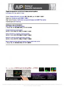
1. Introduction Firefighters use protective gloves (fig. 1a) to defend themselves from hazards like burning or cutting. Unfortunately while using them they are not sensitive enough for perception of heat and danger. Before entering a room with unknown fire danger they have to undress their gloves to feel the temperature of the door. This cause additional danger and necessary rescue time is lost. On the other hand they have to enter a burning room and want to be sure if their protective defend them from heat. If the inner temperature reaches a critical level very fast a thermal breakdown can occur where the heat protection fails, so a warning procedure is needed to prepare the firefighter for escape.
1877-7058 © 2012 The Authors. Published by Elsevier Ltd. Selection and/or peer-review under responsibility of the Symposium Cracoviense Sp. z.o.o. Open access under CC BY-NC-ND license. doi:10.1016/j.proeng.2012.09.221
612
D. Mrugala et al. / Procedia Engineering 47 (2012) 611 – 614
Fig. 1. (a) Firefighter glove (b) Textile integration process of the whole system
2. Glove integration The integration process of electronics into a firefighter glove has other boundary conditions than for example medical or commercial applications. The most important are: x
x x x
It is absolutely necessary to fulfill the EN 659 standard for firefighter gloves. E.g. the glove should withstand temperatures above 1000 °C for some seconds (in case of a flash over). Because of high electrical and heat conductivity of metals external wires or electronics could burn the hand while annealing. For this reason a penetration of textile layers with conductors or the use of electronic textiles for example are not possible. A complete sensor system with sensors, haptic feedback and wide rage wireless communication has to be integrated into the glove (not only some subsystems). The system has to be customized by software for fire fighter conditions (ambient intelligence) The glove should be washable with all electronics except the batteries.
These conditions led designing the whole temperature measurement system between textile layers. The preparation of the system passes through several steps. Primary there is a design of a circuit board with stiff and flexible parts. After the insertion of electrical components [1] a grouting is necessary for wash ability. To protect the circuit from heat hazards while keeping it shock-proof silicon based grouting of the stiff circuit parts has been chosen. To get a reference for sewing up into textile, a piece of textile has been glued on the backside. To keep heat and cut protection of the glove the whole system is placed behind a heat resistive layer (Nomex) and a membrane (Goretex). This makes also the manufacturing process more easily, because heat is necessary for the generating of a glove with these layers. The latest coat layer has been used for fitting of the whole circuit design into the glove (fig 1b). This layer has low heat capacity and furnishes comfort while wearing the glove. The thermocouple design as flexible circuit part is then crooked over 180 degrees while maintaining a curvature and avoiding buckling of the flex part. To avoid dead time while heat flux measurement the last critical step is the generation of a reliable heat contact using the copper disc of the thermocouple. This has been done using more quantity of the same silicon glue as for the membrane integration. In addition to the slightly pressure of the crooked flex part against the membrane a reliable heat contact without air locks in between the textile layers has been reached on this area. The contact area lies on the back hand of the glove and the fire fighter has to press this area against a door to get the heat information. 3. Design configuration of the Temperature Sensor System The designed temperature sensor system is a monolithic solution of sensors, circuit and processor for analysis and haptic feedback generation. An overview of all electronic components is shown in [1].
613
D. Mrugala et al. / Procedia Engineering 47 (2012) 611 – 614
Vib[0]=low
Vib[0]=mid
Vib[0]=high
Vib[0]=off
Vib[0]=low
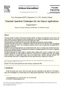
Fig. 2. (a) circuit design of the thermocouple amplification; (b) software procedure of contact heat measurement
A thermocouple is integrated into a flexible circuit board for contact heat measurement whereas absolute temperature measurements have been done by a standardized resistance thermometer. Both are connected to electronics with conductor paths. In case of the thermocouple, the conductor path is copper as bimetallic part. To reach reliable temperature differences the copper path has been designed as a meander on the flexible circuit board. This meander continues to the stiff circuit board where it is connected as one bimetallic to the electronics. The other bimetallic is a constantan (also known as resistance) wire. This wire is soldered between measurement and reference contact whereas the reference contact is also on the flexible circuit board but has a short path to the electronics (fig. 3).
Fig. 3. Design of the temperature sensor system
The heat contact is designed as a copper disc of 10 mm diameter with pin hole for soldering of the constantan wire. This huge contact offers more accuracy to the heat flux measurement using the backhand of the glove. Because grounding would increase the reaction time, both bimetallic paths are directly connected to a differential amplifier. The amplified and noise reduced signal is then digitalized using an internal Analog Digital converter inside the microprocessor (AD1). In addition the signal is amplified again while using a fixed voltage threshold (AD2). This second amplification is necessary to measure small heat differences through several textile layers. The circuit is shown in fig. 2 (a). Temperature measurement procedure
channel
heat contact (low) heat contact (middle) heat contact (high) heat contact (very high) thermal breakdown heat convection (yellow alarm) heat convection (red alarm) deactivation of heat alarm
AD2 AD2 AD2 AD2 AD3 AD3 AD3 AD1
thermal Difference 10 °C 20 °C 30 °C 40 °C >37°C >45°C
value (of 1023) min. max. 10 30 31 112 113 349 350 1023 >4 707 805 0 707