Oct 19, 2018 - acts as a prior for the reconstruction and, when chosen reasonably close in a deformation .... term that quantifies the misfit of the solution against the ... the best of our knowledge, the results obtained for indirect image ...... x 2 y 2 +. 2(x y)2x x 4 y 2 respectively. Moreover, the derivatives of (25) are given by. â.
Template-Based Image Reconstruction from Sparse Tomographic Data Lukas F. Lang1 , Sebastian Neumayer2 , Ozan Öktem3 , and Carola-Bibiane Schönlieb1
arXiv:1810.08596v1 [math.OC] 19 Oct 2018
1
Department of Applied Mathematics and Theoretical Physics, University of Cambridge, Wilberforce Road, Cambridge CB3 0WA, United Kingdom 2 Department of Mathematics, Technische Universität Kaiserslautern, D-67663 Kaiserslautern, Germany 3 Department of Mathematics, KTH-Royal Institute of Technology, 100 44 Stockholm, Sweden
Abstract We propose a variational regularisation approach for the problem of template-based image reconstruction from indirect, noisy measurements as given, for instance, in X-ray computed tomography. An image is reconstructed from such measurements by deforming a given template image. The image registration is directly incorporated into the variational regularisation approach in the form of a partial differential equation that models the registration as either mass- or intensity-preserving transport from the template to the unknown reconstruction. We provide theoretical results for the proposed variational regularisation for both cases. In particular, we prove existence of a minimiser, stability with respect to the data, and convergence for vanishing noise when either of the abovementioned equations is imposed and more general distance functions are used. Numerically, we solve the problem by extending existing Lagrangian methods and propose a multilevel approach that is applicable whenever a suitable downsampling procedure for the operator and the measured data can be provided. Finally, we demonstrate the performance of our method for template-based image reconstruction from highly undersampled and noisy Radon transform data. We compare results for massand intensity-preserving image registration, various regularisation functionals, and different distance functions. Our results show that very reasonable reconstructions can be obtained when only few measurements are available and demonstrate that the use of a normalised cross correlation-based distance is advantageous when the image intensities between the template and the unknown image differ substantially.
1 Introduction In medical imaging, an image can typically not be observed directly but only through indirect and potentially noisy measurements, as it is the case, for example, in computed tomography (CT) [38]. Due to the severe ill-posedness of the problem, reconstructing an image from measurements is rendered particularly challenging when only few or partial
1
measurements are available. This is, for instance, the case in limited-angle computed tomography [21, 38], where limited-angle data is acquired in order to minimise exposure time of organisms to X-radiation. Therefore, it can be beneficial to impose a priori information on the reconstruction, for instance, in the form of a template image. However, typically neither its exact position nor its exact shape is known. In image registration, the goal is to find a reasonable deformation of a given template image so that it matches a given target image as closely as possible according to a predefined similarity measure, see [37, 36] for an introduction. When the target image is unknown and only given through indirect measurements, it is referred to as indirect image registration and has been explored only recently [11, 23, 28, 42]. As a result, a deformation together with a transformed template can be computed from tomographic data. The prescribed template acts as a prior for the reconstruction and, when chosen reasonably close in a deformation sense, gives outstanding reconstructions in situations where only few measurements are available and competing methods such as filtered backprojection [38] or total variation regularisation [44] fail, see [11, Sec. 10]. In our setting, deformations are maps from the image domain Ω ⊂ Rn , n ∈ N, to itself together with an action that specifies exactly how such a map deforms elements in the shape space, which in this work is the space L2 (Ω, R) of greyscale images supported in the image domain. Natural problems are to characterise admissible deformations and to compute these numerically in an efficient manner. One possible approach is diffeomorphic image registration, where the set of admissible deformations is restricted to diffeomorphisms in order to preserve the topology of structures within an image [55]. One can, for instance, consider the group of diffeomorphisms together with the composition as group operation. Elements in this group act on greyscale images by means of the group action and thereby allow for a rich set of non-rigid deformations, as required in many applications. For instance, the geometric group action transforms greyscale images in a way such that its intensity values are preserved, whereas the masspreserving group action ensures that, when the image is regarded as a density, the integral over the density is preserved. A computational challenge in using the above group formalism is that it lacks a natural vector space structure, which is typically desired for the numerical realisation of the scheme. Hence, it is convenient to further restrict the set of admissible deformations. One way to obtain diffeomorphic deformations is to perturb the identity map with a displacement vector field. Provided that the vector field is reasonably small and sufficiently regular, the resulting map is invertible [55, Prop. 8.6]. For indirect image registration this idea was pursued in [42]. The basic idea of the large deformation diffeomorphic mapping (LDDMM) [4, 17, 33, 34, 47, 50, 55] framework is to generate large deformations by considering flows of diffeomorphisms that arise as the solution of an ordinary differential equation (ODE), the so-called flow equation, with velocity fields that stem from a reproducing kernel Hilbert space. In order to ensure that the flow equation admits a unique solution, one typically chooses this vector space so that it can be continuously embedded into C 1 (Ω, Rn ), allowing the application of existence and uniqueness results from Cauchy–Lipschitz theory for ODEs, see [14, Chap. 1] for a brief introduction. In [11], the LDDMM framework is adapted for indirect image registration and the authors prove existence, stability, and convergence of solutions for their variational formulation. Numerically, the problem is solved by gradient descent.
2
The variational problem associated with LDDMM is typically formulated as an ODEconstrained optimisation problem. As the flow equation can be directly related to hyperbolic partial differential equations (PDE) via the method of characteristics [20, Chap. 3.2], the problem can equivalently be rephrased as a PDE-constrained optimisation problem [30]. The resulting PDE is determined by the chosen group action, see [11, Sec. 6.1.1] for a brief discussion. For instance, the geometric group action is associated with the transport (or advection) equation, while the mass-preserving group action is associated with the continuity equation, respectively. It is important to highlight that the PDE constraint implements both the flow equation and the chosen diffeomorphic group action. Such an optimal control approach was also pursued for motion estimation and image interpolation [2, 5, 6, 8, 12, 26, 41]. In the terminology of optimal control, the PDE represents the state equation, the velocity field the control, and the transformed image the resulting state. We refer to the books [7, 15, 24, 29] and to the article [27] for a general introduction to PDE-constrained optimisation and suitable numerical methods. Let us mention that other methods, such as geodesic shooting [3, 33, 46, 53], exist and constitute particularly efficient numerical approaches. In particular, this direction has recently been combined with machine learning methods [54]. A particularly challenging scenario for diffeomorphic image registration occurs when the target image is not contained in the orbit of the template image under abovementioned group action of diffeomorphisms. For instance, this could happen in the case of the geometric group action due to the appearance of new structures in the target image or due to a discrepancy between the image intensities of the template and the target image. A possible solution is provided by the metamorphosis framework [35, 43, 48, 49], which is an extension to LDDMM that allows for modulations of the image intensities along characteristics of the flow. The image intensities change according to an additional flow equation with an unknown source. See [55, Chap. 13] for a general introduction and, for instance, [30] for an application to magnetic resonance imaging. Let us also mention [40], which adopts a discrete geodesic path model for the purpose of image reconstruction, and [31], in which the metamorphosis model is combined with optimal transport. In [23], the metamorphosis framework is adapted for indirect image registration. The authors prove that their formulation constitutes a well-defined regularisation method by showing existence, stability, and convergence of solutions. However, in the setting where only few measurements—e.g. a few directions in CT—are available, reconstruction of appearing or disappearing structures seems very challenging. Therefore, in order to obtain robustness with respect to differences in the intensities between the transformed template and the sought target image, we follow a different approach. We consider not only the standard sum-of-squared differences (SSD) but also a distance that is based on the normalised cross correlation (NCC) [37, Chap. 7.2], as it is invariant with respect to a scaling of the image intensities. While image registration itself is already an ill-posed inverse problem that requires regularisation [19], the indirect setting as described above is intrinsically more challenging. It can be phrased as an inverse problem, where measurements (or observations) g ∈ Y are related to an unknown quantity f ∈ X via the operator equation K(f ) = g + nδ .
(1)
Here, K : X → Y is a (not necessarily linear) operator that models the data acquisition,
3
often by means of a physical process, nδ are measurement errors such as noise, and X and Y are Banach spaces. When f constitutes an image and g are tomographic measurements, solving (1) is often referred to as image reconstruction. We use a variational scheme [45] to solve the inverse problem of indirect image registration, which can be formulated as a PDE-constrained optimisation problem [11, Sec. 6.1.1]. It is given by min Jγ,g (v), v∈V (2) s.t. C(v), where Jγ,g : V → [0, +∞] is the functional v 7→ D(K(fv (T, ·)), g) + γkvk2V .
(3)
Here, V is an admissible vector space with norm k · kV , D : Y × Y → R≥0 is a data fidelity term that quantifies the misfit of the solution against the measurements, and γ > 0 is a regularisation parameter. Moreover, fv (T, ·) : Ω → R denotes the evaluation at time T > 0 of the (weak) solution of C(v), which is either the Cauchy problem + v(t, x)∇x f (t, x) = 0, for (t, x) ∈ [0, T ] × Ω, f (0, x) = f0 (x), for x ∈ Ω,
(
C(v) =
∂ ∂t f (t, x)
governed by the transport equation, or + divx v(t, x)f (t, x) = 0, for (t, x) ∈ [0, T ] × Ω, f (0, x) = f0 (x), for x ∈ Ω,
(
C(v) =
∂ ∂t f (t, x)
�
involving the continuity equation. Here, f0 ∈ L2 (Ω, R) denotes an initial condition, which in our case is the template image. The main goals of this article are the following. First, to study variational and regularising properties of problem (2), and to develop efficient numerical methods for solving it. Second, to investigate alternative choices of distance functions D, such as the abovementioned NCCbased distance. Third, to demonstrate experimentally that excellent reconstructions can be computed from highly undersampled and noisy Radon transform data. Our numerical approach is based on the Lagrangian methods developed in [32], called LagLDDMM. In contrast to most existing approaches, which are mainly first-order methods (see [32] for a brief classification and discussion), LagLDDMM uses a Gauss–Newton–Krylov method paired with Lagrangian solvers for the hyperbolic PDEs listed above. The characteristics associated with these PDEs are computed with an explicit Runge–Kutta method. One of the main advantages of this approach is that Lagrangian methods are unconditionally stable with regard to the admissible step size. Furthermore, the approach limits numerical diffusion and, in order to evaluate the gradient or the Hessian required for optimisation, does not require the storage of multiple space-time vector fields or images at intermediate time instants. The scheme can also be implemented matrix-free. Contributions The contributions of this article are as follows. First, we provide the necessary theoretical background on (weak) solutions of the continuity and the transport equation, and recapitulate existence and uniqueness theory for characteristic curves for the
4
associated ODE. In contrast to the results derived in [11], where the template image is assumed to be contained in the space SBV (Ω, R) ∩ L∞ (Ω, R) of essentially bounded functions with special bounded variation, our results only require L2 (Ω, R) regularity. In addition, by using results from [16], we are able to consider the transport equation in the setting with H 1 regularity of vector fields in space as well as in time and with bounded divergence. Moreover, we show the existence of a minimiser of the problem (2), stability with respect to the data, and convergence for vanishing noise. Second, in order to solve the problem numerically, we follow a discretise-then-optimise approach and extend the LagLDDMM framework [32] to the indirect setting. The library itself is an extension of FAIR [37] and, as a result, our implementation provides great flexibility regarding the selected PDE, and can easily be extended to other distances as well as to other regularisation functionals. The source code of our Matlab implementation is available online.1 Finally, we present numerical results for the abovementioned distances and PDEs. To the best of our knowledge, the results obtained for indirect image reconstruction based on the continuity equation are entirely novel. Moreover, we propose to use the NCC-based distance instead of SSD whenever the image intensities of the template and the unknown target are far apart, and show its numerical feasibility.
2 Theoretical results on the transport and continuity equation In this section, we review the necessary theoretical background, and state results on the existence and stability of weak solutions of the transport and the continuity equation. Compared to [11], our results are stronger since we do not require space regularity of the template image.
2.1 Continuity equation In what follows, we consider well-posedness of the continuity equation that arises in the LDDMM framework using the mass-preserving group action via the method of characteristics. The regularity assumptions on v are such that we can apply the theory from [48]. Let Ω ⊂ Rn be a bounded, open, convex domain with Lipschitz boundary and let T > 0. In the following, we examine the continuity equation � ∂ f (t, x) + divx v(t, x)f (t, x) = 0 ∂t
f (0, x) = f0 (x)
for (t, x) ∈ [0, T ] × Ω, for x ∈ Ω,
(4)
with coefficients v ∈ L2 ([0, T ], V) and initial condition f0 ∈ L2 (Ω, R), where V is a Banach space which is continuously embedded into C01,α (Ω, Rn ) for some α > 0. Here C01,α (Ω, Rn ) denotes the closure of Cc∞ (Ω, Rn ) under the C 1,α norm. Note that such velocity fields can be continuously extended to the boundary. Clearly, equation (4) has to be understood in a weak sense, i.e. a function f ∈ C 0 ([0, T ], L2 (Ω, R)) is said to be a weak solution of (4) if Z TZ 0 1
Ω
�
f (t, x) v(t, x)∇x η(t, x) +
� ∂ η(t, x) dx dt + ∂t
Z Ω
f0 (x)η(0, x) dx = 0
(5)
Source code will be made available upon publication and can be provided by request for reviewing purpose.
5
holds for all η ∈ Cc∞ ([0, T ) × Ω). The corresponding characteristic ODE is � d X(t, s, x) = v t, X(t, s, x) dt
for (t, s, x) ∈ [0, T ] × [0, T ] × Ω,
X(s, s, x) = x for x ∈ Ω.
(6)
In this notation, the first argument of X is the time dependence, the second the initial time, and the third the initial space coordinate. The following theorem is a reformulation of [48, Thms. 1 and 9] and characterises solutions of (6). Theorem 2.1.1. Let v ∈ L2 ([0, T ], V) and s ∈ [0, T ] be given. There exists a unique global solution X(·, s, ·) ∈ C 0 ([0, T ], C 1 (Ω, Rn )) such that X(s, s, x) = x for all x ∈ Ω and d X(t, s, x) = v(t, X(t, s, x)) dt in weak sense (absolutely continuous solutions). The solution operator Xv : L2 ([0, T ], V) → C 0 ([0, T ] × Ω, Rn ) assigning a flow Xv to every velocity field v is continuous with respect to to the weak topology in L2 ([0, T ], V). Since X(0, t, X(t, 0, x)) = x, we can directly conclude that X(t, 0, ·) is a diffeomorphism for every t ∈ [0, T ]. Now, the diffeomorphism X(0, t, x) can be used to characterise solutions of (4) as follows. Proposition 2.1.2. If v ∈ L2 ([0, T ], V), then the unique weak solution of (4), as defined in (5), is given by f (t, x) = det(Dx X(0, t, x))f0 (X(0, t, x)), where Dx X denotes the Jacobian of X. Proof. The proof is divided in three steps. First, we want to show that f satisfies the regularity conditions of weak solutions. For this purpose, the first step is to show X(0, ·, ·) ∈ C 0 ([0, T ], C 0 (Ω, Rn )), i.e. that the flow is continuous in the initial values. Clearly, X(0, t, ·) ∈ C 0 (Ω, Rn ) for every t ∈ [0, T ]. For an arbitrary sequence ti → t we get kX(0, ti , ·) − X(0, t, ·)kC 0 (Ω) ≤ kDx X(0, ti , ·)kC 0 (Ω) kId − X(ti , t, ·)kC 0 (Ω) → 0, where the first factor is bounded due to [48, Lemma 9]. Next, using the sequence Xi (·) = X(0, ti , ·), it follows f0 (X(0, ·, ·)) ∈ C 0 ([0, T ], L2 (Ω, R)), where the continuity in time follows from [39, Cor. 3]. Then, by differentiating X(0, t, X(t, 0, x)) = x and rearranging the terms we obtain det(Dx X(0, ·, ·)) = det(Dx X(·, 0, ·))−1 (X(0, ·, ·)) ∈ C 0 ([0, T ] × Ω), since all involved expressions are continuous. Finally, we conclude f ∈ C 0 ([0, T ], L2 (Ω, R)), which follows from kf (t, ·) − f (ti , ·)kL2 (Ω) ≤ k det(Dx X(0, t, x)) − det(Dx X(0, ti , x))kC 0 (Ω) kf0 (X(0, t, x))kL2 (Ω) + k det(Dx X(0, ti , x))kC 0 (Ω) kf0 (X(0, t, x)) − f0 (X(0, ti , x))kL2 (Ω) , (7)
6
since both summands converge to zero. The second step is to show that (5) is satisfied. Note that X(·, 0, x) is differentiable in t for a.e. t ∈ [0, T ], since it is absolutely continuous by definition. By inserting f into (5) and using the transformation formula, we get Z TZ 0
=
∂η(t, x) f (t, x) v(t, x)∇x η(t, x) + ∂t Ω �
Z TZ 0
Ω
�
�d
det Dx X(t, 0, x) f t, X(t, 0, x) �
=
Z TZ 0
dx dt +
Ω
f0 (x)
dt
Z Ω
f0 (x)η(0, x) dx
η t, X(t, 0, x) dx dt + �
� d η t, X(t, 0, x) dx dt + dt
Z Ω
Z Ω
f0 (x)η(0, x) dx
f0 (x)η(0, x) dx = 0. (8)
For the last equality we used that η(t, X(t, 0, x)) is absolutely continuous. The last step is to prove uniqueness of weak solutions, i.e. that every solution has the given form. Let f1 , f2 be two different solutions, then we can find a t such that kf1 (t, ·) − f2 (t, ·)kL2 (Ω) > 0. By continuity in time we can find an interval I of length δ > 0 that contains t, and a constant c > 0 such that kf1 (s, ·) − f2 (s, ·)kL2 (Ω) ≥ c for all s ∈ I. However, weak solutions are unique in L∞ ([0, T ], L2 (Ω, R)), see [16, Cor. II.1], where we used the embedding of V into C01 (Ω, Rn ). This yields a contradiction. Additionally, we can state and prove the following stability result for solutions of (4). Proposition 2.1.3 (Stability). Let vi * v in L2 ([0, T ], V) and fi denote the weak solution of (4) corresponding to vi . Then for every t ∈ [0, T ], there exists a subsequence, also denoted with fi , such that fi (t, ·) → f (t, ·) in L2 (Ω, R). Proof. The solution of (6) corresponding to vi is denoted by Xi . Fix an arbitrary t ∈ [0, T ]. From Thm. 2.1.1 we conclude kXi (0, t, ·) − X(0, t, ·)kC 0 (Ω) → 0. Further, [18, Thm. 3.1.10] implies that Xi (0, t, ·) is uniformly bounded for all i ∈ N in C 1,α (Ω), which implies f0 (Xi (0, t, ·)) → f0 (X(0, t, ·)) in L2 (Ω, R) by [39, Cor. 3]. It is left to show that a subsequence, also denoted by Xi , exists such that Xi (0, t, ·) → X(0, t, ·) in C 1 (Ω, Rn ). This concludes the proof since it also implies the convergence of det(Dx Xi (0, t, ·)) → det(Dx X(0, t, ·)) in C 0 (Ω). However, Xi (0, t, ·) is uniformly bounded in C 1,α (Ω, Rn ) and it follows that Dx Xi (0, t, ·) is uniformly bounded in C 0,α (Ω, Rn×n ). By using the compact embedding of C 0,α (Ω, Rn×n ) into C 0 (Ω, Rn×n ) [22, Lemma 6.33], there exists a subsequence of Xi (0, t, ·) that converges to X(0, t, ·) in C 1 (Ω, Rn ).
2.2 Transport equation with H 1 regularity Here, we prove well-posedness of the transport equation that arises in the LDDMM framework using the geometric group action. Compared to the previous section, the space regularity assumptions on v are weaker and fit the setting in [16]. The transport equation reads as ∂ f (t, x) + v(t, x)∇x f (t, x) = 0 ∂t
f (0, x) = f0 (x)
7
for (t, x) ∈ [0, T ] × Ω, for x ∈ Ω,
(9)
with coefficients n
v ∈ A := v ∈ H 1 ([0, T ] × Ω)n ∩ L2 ([0, T ], H01 (Ω)n ) : k divx vkL∞ ([0,T ]×Ω) ≤ C
o
(10)
for some fixed constant C and initial value f0 ∈ L2 (Ω, R). The admissible set A consists of all H 1 functions that are zero on the boundary of the spatial domain and have bounded divergence in the L∞ norm. Note that the set A is a subset of H 1 ([0, T ] × Ω)n , which is closed and convex so that it is a weakly closed subset of a reflexive Banach space. In the following, we only check that A is closed. Let vi be a convergent sequence in A with limit v. Since the two involved spaces are Banach spaces, we only have to check that v satisfies the constraint. Assume that k divx vkL∞ ([0,T ]×Ω) > C, then there exists a set B with positive measure and an � > 0 such that for all x ∈ B we have | divx v(x)| ≥ C + �. Hence, we get k divx vi − divx vkL2 ([0,T ]×Ω) ≥ p µ(B)�, which contradicts the convergence in H 1 . Again, equation (9) has to be understood in the weak sense so that f ∈ C 0 ([0, T ], L2 (Ω, R)) is said to be a solution of (9) if it satisfies Z TZ 0
� ∂ f (t, x) divx v(t, x)η(t, x) + η(t, x) dx dt + ∂t Ω �
�
Z Ω
f0 (x)η(0, x) dx = 0
(11)
for all η ∈ Cc∞ ([0, T ) × Ω). The next theorem is an existence and stability result, see [16, Cors. II.1 and II.2, Thm. II.5]. Theorem 2.2.1 (Existence & Stability). For every v ∈ A there exists a unique weak solution f ∈ C 0 ([0, T ], L2 (Ω, R)) of (9). If vi ∈ A converges to v ∈ A in the norm of L2 ([0, T ] × Ω, Rn ), then the corresponding sequence of weak solutions fi ∈ C 0 ([0, T ], L2 (Ω, R)) converges to f in C 0 ([0, T ], L2 (Ω, R)). Proof. The existence and uniqueness of weak solutions follows from [16, Corrs. II.1 and II.2]. Note that these solutions are also renormalised due to [16, Thm. II.3]. We recast the second part of the theorem such that it has the exact form of [16, Thm. II.5]. First, note that both the velocity fields and the initial condition can be extended to Rn by zero outside of Ω due to boundary condition of A. Due to the conditions on v, the weak formulation is equivalent to the one for the extension in the Rn setting. The uniform boundedness condition on fi is satisfied since Ω is bounded. Corollary 2.2.2. Let vi * v ∈ A with the inner product of H 1 ([0, T ] × Ω)n . Then, fi converges to f in C 0 ([0, T ], L2 (Ω, R)). Proof. Combine the previous theorem with the compact embedding of H 1 ([0, T ] × Ω)n into L2 ([0, T ] × Ω)n (Rellich embedding theorem [1, A6.4]). Remark 2.2.3. Note that the same arguments can be used if we use higher spatial regularity, such as H 2 , in this section. From a numerical point of view, the bound on the divergence is always satisfied for C large enough if we use linear interpolation for the velocities on a fixed grid. Here we use that all norms are equivalent on finite dimensional spaces.
8
3 Regularising properties of template-based image reconstruction In this section, we prove regularising properties of template-based reconstruction as defined in (2). Recall that the problem reads min D(K(fv (T, ·)), g) + γkvk2V , v∈V
s.t. C(v), where C(v) is the Cauchy problem with either the transport or the continuity equation. The admissible set V is chosen such that the regularity requirements stated in the previous section are satisfied. For the following considerations we require these assumptions on K and D: 1. The operator K is continuous, D(·, g) is lower semi-continuous for each g ∈ Y , and D(g, ·) is continuous for each g ∈ Y . 2. If fn , gn are two convergent sequences with limits f and g, respectively, then D must satisfy lim inf n→∞ D(fn , g) ≤ lim inf n→∞ D(fn , gn ). 3. If D(f, g) = 0, then f = g. Note that the requirements on D are satisfied if D is a metric. The obtained results are along the lines of [11] but are adapted to our setting and to our notation. For simplicity we stick to the notation of the continuity equation, but want to mention that the same derivations hold for the transport equation with coefficients in the set A. First, we prove that a minimiser of the problem exists. Proposition 3.0.1 (Existence). For every f0 ∈ L2 (Ω, R), the functional Jγ,g defined in (3) has a minimiser. Proof. The idea of the proof is to construct a minimising sequence which is weakly convergent and then use that the functional is weakly lower semi-continuous. Let us consider a sequence vn such that Jγ,g (vn ) converges to inf v Jγ,g (v). By construction of the functional, vn is bounded in L2 ([0, T ], V) and hence there exists a subsequence, also denoted with vn , such that vn * v∞ . By Prop. 2.1.3, there exists a subsequence, also denoted with vn , such that fvn (T, ·) → fv∞ (T, ·) in L2 (Ω, R). With this at hand, we are able to prove weak lower semi-continuity of the data term. Indeed, as K is continuous, from fvn (T, ·) → fv∞ (T, ·) we get K(fvn (T, ·)) → K(fv∞ (T, ·)). Since D(·, g) is lower semi-continuous, we obtain that D(K(fv∞ (T, ·)), g) ≤ lim inf n→∞ D(K(fvn (T, ·)), g). This concludes the proof, since the whole functional is (weakly) lower semi-continuous, and hence Jγ,g (v∞ ) ≤ inf v Jγ,g (v). Next, we state a stability result. Proposition 3.0.2 (Stability). Let f0 ∈ L2 (Ω, R) and γ > 0. Let gn be a sequence in Y converging to g ∈ Y . For each n, we choose vn as minimiser of Jγ,gn . Then, there exists a subsequence of vn which weakly converges towards a minimiser v of Jγ,g . Proof. By the properties of D it holds, for every n, that kvn k2V ≤
1 1 1 1 Jγ,gn (vn ) ≤ Jγ,gn (0) = D(K(f0 ), gn ) → D(K(f0 ), g) < ∞. γ γ γ γ
9
Hence, vn is bounded in L2 ([0, T ], V) and there exists a subsequence, also denoted with vn , such that vn * v. From the weak convergence we obtain γkvk2V ≤ γ lim inf n→∞ kvn k2V . By passing to a subsequence and by using Prop. 2.1.3, we deduce that fvn (T, ·) → fv (T, ·). Together with the convergence of gn and the convergence property of D this implies D(K(fv (T, ·)), g) ≤ lim inf D(K(fvn (T, ·)), g) ≤ lim inf D(K(fvn (T, ·)), gn ). n→∞
n→∞
Thus, for any v˜, it holds that v ), Jγ,g (v) ≤ lim inf γkvn k2V + D(K(fvn (T, ·)), gn ) = lim inf Jγ,gn (vn ) ≤ lim inf Jγ,gn (˜ n→∞
n→∞
n→∞
v ) converges to Jγ,g (˜ v ) by the assumptions on because vn minimises Jγ,gn . Then, as Jγ,gn (˜ D, we deduce Jγ,g (v) ≤ Jγ,g (˜ v ) and hence that v minimises Jγ,g . Finally, we state a convergence result for the method. Proposition 3.0.3 (Convergence). Let f0 ∈ L2 (Ω, R) and g ∈ Y , and suppose that there exists vˆ ∈ L2 ([0, T ], V) such that K(fvˆ (T, ·)) = g. Further, assume that γ : R>0 7→ R>0 δ satisfies γ(δ) → 0 and γ(δ) → 0 as δ → 0. Now let δn be a sequence of positive numbers converging to 0 and assume that gn is a data sequence satisfying D(g, gn ) ≤ δn for each n. Let vn be a minimiser of Jγn ,gn , where γn = γ(δn ). Then, there exists a subsequence of vn which weakly converges towards an element v such that K(fv (T, ·)) = g. Proof. For every n, it holds that kvn k2V ≤
� δn 1 1 1 Jγn ,gn (vn ) ≤ Jγn ,gn (ˆ v) = D(g, gn ) + γn kˆ v k2V ≤ + kˆ v k2V . γn γn γn γn
(12)
From the requirements on γ and δ we deduce that vn is bounded in L2 ([0, T ], V) and then that up to an extraction, vn weakly converges to some v in L2 ([0, T ], V). Further, it holds D(K(fv (T, ·)), g) ≤ lim inf n→∞ D(K(fvn (T, ·)), gn ) with the same arguments as in the previous proposition. Finally, for every n, it holds that D(K(fvn (T, ·)), gn ) ≤ Jγn ,gn (vn ) ≤ Jγn ,gn (ˆ v ) = D(g, gn ) + γn kˆ v k2V ,
(13)
where the two rightmost terms both converge to zero. Thus, K(fv (T, ·)) = g by the assumptions on D. We conclude with a remark on data discrepancy functionals that satisfy the conditions and will be used in our numerical experiments in Sec. 5. Remark 3.0.4. We now assume that the data space Y is a real Hilbert space. Clearly, the conditions are satisfied if DSSD (f, g) = kf − gk2Y . We will only check the convergence condition. It holds lim inf kfn − gk2Y = lim inf kfn − gn k2Y + 2hfn − gn , gn − gi + kg − gn k2Y , n→∞
n→∞
where the last two terms converge to zero since convergent sequences are bounded.
10
Another function that satisfies the conditions is DNCC : Y \ {0} × Y \ {0} → [0, 1] with DNCC (f, g) = 1 −
hf, gi2 , kf k2Y kgk2Y
˜ g) = which is based on the normalised cross correlation. First, note that D(·, k · k−2 Y
h·,gi2 kgk2Y
and the
function are continuous. Thus, we get that DNCC (·, g) is continuous. By symmetry, this also holds for DNCC (g, ·). It remains to check the convergence property: (hfn , g − gn i + hfn , gn i)2 hfn , gn i2 = lim n→∞ n→∞ kfn k2 kgk2 kfn k2Y kgk2Y Y Y hfn , gn i2 = lim = lim 1 − DNCC (fn , gn ). n→∞ kfn k2 kgn k2 n→∞ Y Y
lim 1 − DNCC (fn , g) = lim
n→∞
(14) (15)
From this we conclude lim inf n→∞ DNCC (fn , g) = lim inf n→∞ DNCC (fn , gn ). Unfortunately, DNCC (f, g) = 0 only implies f = cg, with c ∈ R.
4 Numerical solution The focus of this section is to approximately solve problem (2). Our approach is based on the Lagrangian methods developed in [32] and the inexact multilevel Gauss–Newton method used in [37]. Both methods and their necessary modifications are briefly outlined here. As customary in PDE-constrained optimisation [15, Chap. 3], we eliminate the state equation by defining a control-to-state operator, which parametrises the final state fv (T, ·) in terms of the unknown velocities v. With a slight abuse of notation, we define this solution map as S : V → L2 (Ω, R), (16) v 7→ fv (T, ·) =: f (v). Here, fv denotes the unique solution to either the transport or the continuity equation, as defined in Sec. 2. As a result, we obtain the reduced form of (2): min D(K(f (v)), g) + γR(v). v∈V
(17)
Here, R : V → R≥0 is a regularisation functional that can be written as R(v) =
1 2
Z TZ 0
Ω
kBv(t, x)k2 dx dt
(18)
with B denoting a linear (vectorial) differential operator. In this work, we consider the operators B = ∇x and B = ∆x , which are also used in [32]. We refer to the resulting functionals R as diffusion and curvature regularisation functionals, respectively. Note that B can as well be chosen to incorporate derivatives with respect to time. Amongst the operators above, we also consider a regularisation functional that resembles the norm of the space V = L2 ([0, T ], H03 (Ω, Rn )). This particular choice is motivated by the
11
fact that, for n = {2, 3}, the space H03 (Ω, Rn ) can be continuously embedded in C01,α (Ω, Rn ), for some α > 0, so that the results in Sec. 2 hold. The norm of V is given by kvk2V =
1 2
Z T 0
kv(t, ·)k2L2 (Ω,Rn ) dt +
1 2
Z T 0
|v(t, ·)|2H 3 (Ω,Rn ) dt.
(19)
Here, |·|H k (Ω,Rn ) denotes the usual H k -seminorm including only the highest-order partial derivatives. By the Gagliardo–Nirenberg inequality, (19) is equivalent to the usual norm of L2 ([0, T ], H03 (Ω, Rn )). To simplify numerical optimisation, we omit the requirement that v is compactly supported in Ω and minimise over L2 ([0, T ], H 3 (Ω, Rn )). In order to solve problem (17), we follow a discretise-then-optimise strategy. Without loss of generality, we assume that the domain is Ω = (0, 1)n . We partition it into a regular grid consisting of mn equally sized cells of edge length hX = 1/m in every coordinate direction. The template image f0 ∈ L2 (Ω, R) is assumed to be sampled at cell-centred locations xc ∈ n n m R , giving rise to its discrete version f0 (xc ) ∈ Rm . The template image is interpolated on the cell-centred grid by means of cubic B-spline interpolation as outlined in [37, Chap. 3.4]. Similarly, the time domain is assumed to be [0, 1] and is partitioned into mt equally sized cells of length ht = 1/mt . We assume that the unknown velocities v : [0, 1] × Ω → Rn are sampled at cell-centred locations in space as well as at cell-centred locations in time, leading to a vector of unknowns v ∈ RN , where N = (mt +1)·n·mn is the total number of unknowns of the finite-dimensional minimisation problem. Lagrangian solver In order to compute the solution map f (v) numerically, i.e. to solve the hyperbolic PDEs (4) and (9), the Lagrangian solver in [32] follows a two-step approach. First, given a vector v ∈ RN of velocities, the ODE (6) is solved approximately using a fourth-order Runge–Kutta (RK4) method with Nt equally spaced time steps of size ∆t. For simplicity, we follow the presentation in [32] based on an explicit first-order Euler method and refer to [32, Sec. 3.1] for the full details. n n Given initial points x ∈ Rm and velocities v ∈ RN , an approximation Xv : [0, 1]2 ×Rm → n Rm of the solution Xv is given recursively by Xv (0, tk+1 , x) = Xv (0, tk , x) + ∆t I(v, tk , Xv (0, tk , x)),
(20)
for all k = 0, 1, . . . , Nt − 1, with initial condition Xv (0, 0, x) = x. Here, I(v, tk , Xv (0, tk , x)) denotes a componentwise interpolation of v at time tk = k∆t and at the points Xv (0, tk , x). Note that, since the characteristic curves for both PDEs coincide, this step is identical regardless of which PDE we impose. The second step computes approximate intensities of the final state fv (1, ·). This step depends on the particular PDE. For the transport equation, in order to compute the intensities at the grid points xc , we follow characteristic curves backwards in time, which is achieved by setting ∆t = −1/Nt in (20). The deformed template is then given by f (v) = f0 (Xv (1, 0, xc )), n
(21)
where f0 ∈ Rm is the interpolation of the discrete template image. For the continuity equation, [32] proposes to use a particle-in-cell (PIC) method, see [13] for details. The density of particles which are initially located at grid points xc is
12
represented by a linear combination of basis functions, which are then shifted by following the characteristics computed in the first step. To determine the final density at grid points, exact integration over the grid cells is performed. By setting ∆t = 1/Nt in (20), the transformed template can be computed as f (v) = F(Xv (0, 1, xc ))f0 (xc ),
(22)
where F ∈ RN ×N is the pushforward matrix that computes the integrals over the shifted basis functions. See [32, Sec. 3.1] for its detailed specification using linear, compactly supported basis functions. By design, the method is mass-preserving at the discrete level. Numerical optimisation Let us denote by K : RN → RM , M ∈ N, a finite-dimensional, Fréchet differentiable approximation of the (not necessarily linear) operator K : L2 (Ω, R) → Y . With the application to CT in mind, we will outline a discretisation of (17) suitable for the n-dimensional Radon transform, which maps a function on Rn into the set of its integrals over the hyperplanes in Rn [38, Chap. 2]. An element K(f (v)) ∈ Y is a function on the unit cylinder S n−1 × R of Rn+1 , where S n−1 is the (n − 1)-dimensional unit sphere. We discretise this unit cylinder as follows. First, we sample p ∈ N directions from S n−1 . When n = 2, as it is the case in our experiments in Sec. 5, directions are parametrised by angles from the interval [0, 180] degrees. For simplicity, we say (slightly imprecise) that we take one measurement in each direction. Second, similarly to the sampling of Ω, we use an interval (0, 1) instead of R and partition it into q equally sized cells of length hY = 1/q. Depending on n and the diameter of Ω, the interval length may require adjustment. Each measurement i is then sampled at cell-centred points yc ∈ Rq and denoted by gi (yc ) ∈ Rq . All measurements are then concatenated into a vector g := g(yc ) ∈ RM , where M = p · q. The finite-dimensional optimisation problem in abstract form is then given by min {Jγ,g (v) := D(K(f (v)), g) + γR(v)},
(23)
v∈RN
where D and R are chosen to be discretisations of a distance and of (18), respectively. In further consequence, we approximate integrals using a midpoint quadrature rule. As we are mainly interested in the setting where only few directions are given, we disregard integration over the unit sphere. For vectors x, y ∈ RM , the corresponding approximations of the distance based on sum-of-squared-differences and the normalised cross correlationbased distance are then DSSD (x, y) ≈
hY (x − y)> (x − y) 2
and DNCC (x, y) ≈ 1 −
(x> y)2 , kxk2 kyk2
(24)
respectively. See [37, Chaps. 6.2 and 7.2] for details. Note that, due to cancellation, no (spatial) discretisation parameter occurs in the approximation of the NCC above. Moreover, we approximate the regularisation functional in (18) with R(v) ≈
ht hnX > > v B Bv, 2
(25)
where B ∈ RN ×N is a finite-difference discretisation of the differential operator in (18), analogous to [36, Chap. 8.5]. In our implementation we use zero Neumann boundary conditions
13
and pad the spatial domain to mitigate boundary effects arising from the discretisation of the operator. In order to apply (inexact) Gauss–Newton optimisation to problem (23), we require firstand (approximate) second-order derivatives of Jγ,g (v). By application of the chain rule, we obtain ∂ ∂ ∂ ∂ ∂ Jγ,g (v) = f (v)> K(f (v))> D(K(f (v)), g) + γ R(v), ∂v ∂v ∂f ∂x ∂v where ∂K/∂f is the Fréchet derivative of K and ∂f (v)/∂v is the derivative of the solution map (16) with respect to the velocities, which is given below. The partial derivatives of the distance functions (24) with respect to its first argument are given by ∂ DSSD (x, y) = hY (x − y) ∂x
and
∂2 DSSD (x, y) = hY IN , ∂x2
(26)
where IN ∈ RN ×N is the identity matrix of size N , and 2(x> y)2 x 2(x> y)y ∂ + DNCC (x, y) = − ∂x kxk2 kyk2 kxk4 kyk2 respectively. Moreover, the derivatives of (25) are given by ∂ R(v) = ht hnX B> Bv ∂v
and
∂2 R(v) = ht hnX B> B. ∂v2
In order to obtain an efficient iterative second-order method for solving (23), one requires an approximation of the Hessian H ∈ RN ×N that balances the following tradeoff. Ideally, it is reasonably efficient to compute, consumes limited memory (sparsity is desired), and has sufficient structure so that preconditioning can be used. However, each iteration of the Gauss–Newton method should also provide a suitable descent direction. For these reasons, we approximate the Hessian by H(v) =
2 ∂2 ∂ ∂ ∂ > ∂ > ∂ J (v) ≈ f (v) K(f (v)) D(K(f (v)), g) K(f (v)) f (v) γ,g 2 2 ∂v ∂v ∂f ∂x ∂f ∂v + γht hnX B> B + �IN ,
where � > 0 ensures positive semidefiniteness. For simplicity, the term involving ∂ 2 f (v)/∂v2 is omitted and, regardless of the chosen distance, we use the second derivative in (26) as an approximation of ∂ 2 D(x, y)/∂x2 . In our numerical experiments we found that this choice works well for the problem considered in Sec. 5. It remains to discuss the derivative of the solution map. For the transport equation, the application of the chain rule to (21) yields ∂ ∂ f (v) = ∇x f0 (Xv (1, 0, xc )) Xv (1, 0, xc ), ∂v ∂v where ∇x f0 denotes the gradient of the interpolation of the template image and ∂Xv /∂v is the derivative of the endpoints of the characteristic curves with respect to the velocities,
14
see below. Similarly, for the solution map (22) that corresponds to the continuity equation, we obtain ∂ ∂ ∂ (F(Xv (0, 1, xc ))f0 (xc )) Xv (0, 1, xc ). f (v) = ∂v ∂Xv ∂v Here, ∂F/∂Xv is the derivative of the pushforward matrix with respect to the endpoints of the characteristics, again see [32, Sec. 3.1]. If explicit time stepping methods are used to solve the ODE (6), the partial derivative ∂Xv /∂v can be computed recursively. For example, for the forward Euler approach in (20) it is given by ∂ ∂ ∂ Xv (0, tk+1 , xc ) = Xv (0, tk , xc ) + ∆t I(v, tk , Xv (0, tk , xc )) ∂v ∂v ∂v ∂ ∂ I(v, tk , Xv (0, tk , xc )) Xv (0, tk , xc ), + ∆t ∂Xv ∂v for all k = 0, 1, . . . , Nt −1, with ∂I/∂v and ∂I/∂Xv being the derivatives of the interpolation schemes with respect to the velocities and with respect to the endpoints of the characteristics, respectively. We refer to [37, Chap. 3.5] for details. The case where characteristics are computed backwards in time can be handled similarly. In order to solve the finite-dimensional minimisation problem (23), we apply a inexact Gauss–Newton–Krylov method, which proceeds as follows. Given an initial guess v(0) = 0, we update the velocities in each iteration i = 0, 1, . . . by v(i+1) = v(i) + µδv until a termination criterion is satisfied. Here, µ ∈ R denotes a step size that is determined via Armijo line search and δv ∈ RN is the solution to the linear system H(v(i) )δv = −
∂ Jγ,g (v(i) ). ∂v
(27)
For details on the stopping criteria and the line search we refer to [37, Chap. 6.3.3]. We solve the system (27) approximately by means of a preconditioned conjugate gradient (PCG) method, which can be implemented matrix-free whenever the derivative of K and its adjoint can be computed matrix-free. See [32, Sec. 3.2] for further details on the preconditioning. Due to the non-convexity of (17) and to speed up computation, we use a multilevel strategy in order to reduce the risk of ending up in a local minimum, see [25]. On each level, we use a subsampled version of the velocities that were computed on the previous, more coarser, discretisation as initial guess. While standard image registration typically uses resampling of the template and the target image [37, Chap. 3.7], the approach described here requires multilevel versions of the operator K together with a suitable method for resampling the measurements g. We stress that, if these are not available, optimisation can as well just be performed on the finest discretisation level. In the following, we assume that K is a discretisation of the Radon transform [38], which is a linear operator, and outline a suitable procedure for creating multilevel versions of the operator and the measured data. The former is easily achieved with a computational backend such as ASTRA [51, 52], which allows to explicitly specify the number of grid cells used to discretise the measurement geometry. For the sake of simplicity, we restrict the presentation here to the case where n = 2, i.e. Ω ⊂ R2 , and K is linear.
15
Let us assume that the number of grid cells used to discretise Ω at the finest level is m = 2` , ` ∈ N. In our experiments, we set the number of grid cells of the one-dimensional measurement domain (0, 1) at the current level k ≤ ` to q (k) = 1.5 · 2(k) and set the length of (k) each cell to hY = 1/q (k) . Then, a multilevel representation of each measurement gi , i ≤ p, (k−1) at cell-centred grid points yj = (j − 1/2)hY is given by (k−1)
gi
�
(k)
(k)
(k)
�
(yj ) := gi (yj ) + gi (yj + hY ) /4,
where the denominator arises from averaging over two neighbouring grid points and dividing the edge length of the imaging domain Ω in each coordinate direction in half. The approach can be extended to higher dimensions.
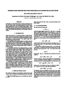
5 Numerical examples In our numerical experiments we use the Radon transform [38] as operator. Other choices are possible and, assuming that one has access to a suitable resampling procedure for the measured data, the multilevel strategy can be applied as well. The aim here is to investigate the reconstruction quality with different regularisation functionals, distances, and noise levels for both PDE constraints. We restrict our examples to the setting n = 2. All shown reconstructions were computed from measurements taken from at most 10 directions (i.e. angles) sampled from intervals within [0, 180] degrees. Before we proceed, we give a brief idea of suitable parameter choices. For the multilevel approach we used in each example 32 × 32 pixels at the coarsest level and 128 × 128 pixels at the finest level, i.e. ` = 7. We use time dependent velocity fields with only one time step, i.e. nt = 1, since this keeps the computational cost reasonable and suffices for our examples. The characteristics are computed using five Runge–Kutta steps, i.e. Nt = 5. As a result, the average computation time in each example was only a few minutes on a consumer laptop. The spatial regularisation parameter depends on the chosen regularisation functional and was chosen in the order of 100 , 102 , and 104 for third-order, curvature, and diffusion regularisation, respectively. The temporal regularisation parameter is less sensitive and was chosen in the order of 102 . Furthermore, the parameter corresponding to the norm of L2 (Ω, Rn ) in (19) was set to zero. In our first example we investigates different regularisation functionals with different noise levels for the transport equation, see Fig. 1. The target is Radon transform data based on a digital brain image and the template is a deformed version thereof. Since we want to focus on the behaviour of the regularisation functionals, we do not treat the continuity equation here. The data was generated using parallel beam tomography with only six equally distributed angles over the interval [0, 60] degrees and was corrupted with Gaussian white noise. Figure 1 shows results obtained from the noiseless data using filtered backprojection and the following two total variation regularisation-based models, see e.g. [9], min kKu − gk2 + γRi (u) u
with R1 (u) := TV(u), R2 (u) := TV(u − f0 ), and γ > 0. Here, R2 (u) incorporates template information. Minimisers of both functionals were computed using the primal-dual
16
(a) Template image.
(b) Unknown image.
(d) Reconstruction using (e) Reconstruction using filtered back-projection. (TV reconstruction).
(c) Measured (sinogram) data without noise.
R1 (f) Reconstruction using with given template.
R2
Figure 1: Comparison of different reconstruction models applied to an artificial brain image [37] that has been deformed manually. We generated six measurements that correspond to six equally spaced angles from the interval [0, 60] degrees. hybrid gradient method [10]. For the case of filtered backprojection, the standard Matlab implementation was used. The results in Fig. 1 highlight why more sophisticated methods, such as template-based approaches, are necessary to obtain satisfying reconstructions in this setting. The results for the different noise levels and different regularisation functionals can be seen in Fig. 2. All results are obtained using the NCC-based distance. As expected, the quality of the reconstruction gets worse for higher noise levels and, consequentially, larger regularisation parameters were necessary. Since data is acquired from only six directions, the influence of the noise is very strong. Especially for the diffusive regularisation we needed to choose large regularisation parameters for higher noise levels, see Fig. 2f. Since diffusion corresponds to first-order regularisation, it is much easier to reconstruct the noise with “rough” deformations. Overall, we found that second- and third-order regularisation performed similar when appropriate regularisation parameters were chosen. Even though some theoretical results only hold for higher-order regularity, second-order regularisation seems sufficient for our use case. In the second example, see Fig. 3, we compare the behaviour of the SSD and the NCC-
17
(a) Curvature regularisation, no (b) Curvature regularisation, (c) Curvature regularisation, noise, SSIM 0.947. 5 % noise, SSIM 0.902. 10 % noise, SSIM 0.832.
(d) Diffusion regularisation, no (e) Diffusion regularisation, 5 % (f) Diffusion regularisation, noise, SSIM 0.916. noise, SSIM 0.875. 10 % noise, SSIM 0.803.
(g) Third-order regularisation, (h) Third-order regularisation, (i) Third-order regularisation, no noise, SSIM 0.943. 5 % noise, SSIM 0.884. 10 % noise, SSIM 0.824.
Figure 2: Reconstructions for the artificial brain image in Fig. 1 using different regularisation functionals. Note that only six measurements were used. The measured data was corrupted with noise of different levels.
18
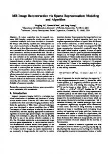
based distance. The example consists of two different hands which, in addition, are rotated relative to each other. Here, the deformation is much larger than in the previous example, but still fairly regular. The data was generated similarly to the previous example, but with only five angles from the interval [0, 75] degrees. Note also that the intensities of the template and target image are different (roughly by a factor of two). First, we discuss the transport equation. The intensity difference is a serious issue if we use the SSD distance, as we can see in Fig. 3e. The hand is deformed into a smaller version in order to compensate the differences. If we use the NCC-based distance instead, which can deal with such discrepancies, the result is much better from a visual point of view. The shapes are well-aligned. The resulting SSIM value is still low, which is not surprising since SSIM is not invariant with respect to intensity differences between perfectly aligned images. However, neither of the two approaches is able to remove or create any of the additional (noise) structures in the images. For the combination SSD with continuity equation, no satisfactory results could be obtained. Since no change of intensity is possible by changing the size of the hand, part of it is moved outside of the image. This behaviour could potentially be corrected if other boundary conditions are used in the implementation. Therefore, we do not provide an example image for this case. Using the NCC-based distance, the results look similar as for the transport equation with slightly worse SSIM value. These results suggest that the NCC-based distance is a more robust choice that avoids unnatural deformations, which would be required in the case of SSD to compensate intensity differences. In the next example, see Fig. 4, we compare the continuity equation with the transport equation as constraint together with the NCC-based distance. The continuity equation allows for limited change of mass along the deformation path. Since the intensity change scales with the determinant of the Jacobian, bigger changes are only possible if areas are compressed or extended a lot. In the presented example this occurs only to a mild extent. For this example, the continuity equation and the transport equation yield visually similar results with minor differences in the SSIM value. As in the previous examples, higher-order regularisation is beneficial and artefacts occur for the diffusion regularisation. In the last example, we used an artificial pair of images consisting of circles, see Fig. 5, to show the possibilities of intensity changes when using the continuity equation as a constraint. Both images are constructed such that the mass of the template image equals the mass of the unknown image. The data was generated as before using only five angles uniformly distributed in the interval [0, 90] degrees. Furthermore, we used curvature regularisation. For the transport equation we observe that the shape is matched, but the intensity is not correct, see Fig. 5d. If we use the continuity equation instead, intensity changes are possible, which can be observed in Fig. 5e. All in all, our results demonstrate that, given a suitable template image, very reasonable reconstructions can efficiently be obtained from only a few measurements, even in the presence of noise. Moreover, our examples show that the NCC-based distance adds robustness to the approach with regard to discrepancies in the image intensities.
6 Conclusions Overall, our numerical examples show that our implementation yields good results, as long as the deformation between template and target is fairly regular. By using the NCC-
19
(a) Template image.
(b) Unknown image.
(c) Measured (sinogram) data without noise.
(d) NCC-based distance with (e) SSD distance with transport (f) NCC-based distance with transport equation, SSIM equation, SSIM 0.545. continuity equation, SSIM 0.6340. 0.584.
Figure 3: Reconstructions of manually deformed Hand [37] images where the template and the target image have different intensity levels. Again, the measured data was obtained by applying the Radon transform to the target image. We generated five measurements that correspond to five equally spaced angles from the interval [0, 75] degrees and added five percent noise. based distance, robustness with respect to intensity differences between the template and the target image can be achieved. As already mentioned in the introduction, we do not follow the metamorphosis approach, since there is to much flexibility in the model and the source term is very likely to reproduce noise and artefacts if the data is too limited. It is left for further research to investigate possible adaptations of the model that allow for the appearance of new objects or structures in the reconstruction without reproducing noise or artefacts. Possibly, the results of our method can be used as better template for other algorithms that require template information. Finally, note that due to the great flexibility of the FAIR library, it is also possible to use a great variety of regularisation functionals for the velocities and other distances, see [37, Chaps. 7 and 8]. Additionally, our implementation is not necessarily restricted to the Radon transform and essentially every (continuous) operator can be used. The multilevel approach can be applied as long as meaningful resampling procedure for the operator and the measured data can be provided.
20
Acknowledgments Lukas F. Lang and Carola-Bibiane Schönlieb acknowledge support from the Leverhulme Trust project “Breaking the non-convexity barrier”, the EPSRC grant EP/M00483X/1, the EPSRC Centre Nr. EP/N014588/1, the RISE projects ChiPS and NoMADS, the Cantab Capital Institute for the Mathematics of Information, and the Alan Turing Institute. Sebastian Neumayer is funded by the German Research Foundation (DFG) within the Research Training Group 1932, project area P3. Ozan Öktem is supported by the Swedish Foundation of Strategic Research, grant AM13-0049.
References [1] H. W. Alt. Linear Functional Analysis: An Application-Oriented Introduction. Universitext. Springer-Verlag, London, 2016. [2] R. Andreev, O. Scherzer, and W. Zulehner. Simultaneous optical flow and source estimation: Space–time discretization and preconditioning. Appl. Numer. Math., 96:72– 81, 2015. [3] J. Ashburner. A fast diffeomorphic image registration algorithm. 38(1):95–113, 2007.
NeuroImage,
[4] M. F. Beg, M. I. Miller, A. Trouvé, and L. Younes. Computing large deformation metric mappings via geodesic flows of diffeomorphisms. Int. J. Comput. Vision, 61(2):139–157, 2005. [5] A. Borzì, K. Ito, and K. Kunisch. An optimal control approach to optical flow computation. Int. J. Numer. Methods Fluids, 40(1-2):231–240, 2002. [6] A. Borzì, K. Ito, and K. Kunisch. Optimal control formulation for determining optical flow. SIAM J. Sci. Comput., 24(3):818–847, 2003. [7] A. Borzìand V. Schulz. Computational Optimization of Systems Governed by Partial Differential Equations, volume 8 of Computational Science & Engineering. Society for Industrial and Applied Mathematics (SIAM), Philadelphia, PA, 2012. [8] M. Burger, H. Dirks, and C.-B. Schönlieb. A variational model for joint motion estimation and image reconstruction. SIAM J. Imaging Sciences, 11(1):94–128, 2018. [9] E. J. Candès, J. K. Romberg, and T. Tao. Robust uncertainty principles: exact signal reconstruction from highly incomplete frequency information. IEEE Trans. Inf. Theory, 52(2):489–509, 2006. [10] A. Chambolle and T. Pock. A first-order primal-dual algorithm for convex problems with applications to imaging. J. Math. Imaging Vision, 40(1):120–145, 2011. [11] C. Chen and O. Öktem. Indirect image registration with large diffeomorphic deformations. SIAM J. Imaging Sciences, 11(1):575–617, 2018.
21
[12] K. Chen and D. A. Lorenz. Image sequence interpolation using optimal control. J. Math. Imaging Vision, 41(3):222–238, 2011. [13] A. Chertock and A. Kurganov. On a practical implementation of particle methods. Appl. Numer. Math., 56:1418–1431, 1999. [14] G. Crippa. The flow associated to weakly differentiable vector fields. PhD thesis, Classe di Scienze Matematiche, Fisiche e Naturali, Scuola Normale Superiore di Pisa / Institut für Mathematik, Universität Zürich, 2007. [15] J. C. De los Reyes. Numerical PDE-Constrained Optimization. Springer International Publishing, 2015. [16] R. J. DiPerna and P.-L. Lions. Ordinary differential equations, transport theory and Sobolev spaces. Invent. Math., 98(3):511–547, 1989. [17] P. Dupuis, U. Grenander, and M.I. Miller. Variational problems on flows of diffeomorphisms for image matching. Quart. Appl. Math., 56:587–600, 1998. [18] A. Effland. Discrete Riemannian Calculus and A Posteriori Error Control on Shape Spaces. Dissertation, University of Bonn, 2017. [19] H. W. Engl, M. Hanke, and A. Neubauer. Regularization of Inverse Problems. Number 375 in Mathematics and its Applications. Kluwer Academic Publishers Group, Dordrecht, 1996. [20] L. C. Evans. Partial Differential Equations, volume 19 of Graduate Studies in Mathematics. American Mathematical Society, Providence, RI, second edition, 2010. [21] J. Frikel. Sparse regularization in limited angle tomography. Appl. Comput. Harmon. Anal., 34(1):117–141, 2013. [22] D. Gilbarg and N. S. Trudinger. Elliptic Partial Differential Equations of Second Order. Classics in Mathematics. Springer-Verlag, Berlin, 2001. Reprint of the 1998 edition. [23] B. Gris, C. Chen, and O. Öktem. Image reconstruction through metamorphosis. Technical report, 2018. [24] M. D. Gunzburger. Perspectives in Flow Control and Optimization. Advances in Design and Control. Society for Industrial and Applied Mathematics (SIAM), Philadelphia, PA, 2003. [25] E. Haber and J. Modersitzki. A multilevel method for image registration. SIAM J. Sci. Comput., 27(5):1594–1607, 2006. [26] G. L. Hart, C. Zach, and M. Niethammer. An optimal control approach for deformable registration. In 2009 IEEE Computer Society Conference on Computer Vision and Pattern Recognition Workshops, volume 2, pages 1223–1227. IEEE, 2009. [27] R. Herzog and K. Kunisch. Algorithms for PDE-constrained optimization. GAMMMitt., 33(2):163–176, 2010.
22
[28] J. Hinkle, M. Szegedi, B. Wang, B. Salter, and S. Joshi. 4D CT image reconstruction with diffeomorphic motion model. Med. Image Anal., 16(6):1307–1316, 2012. [29] M. Hinze, R. Pinnau, M. Ulbrich, and S. Ulbrich. Optimization with PDE Constraints, volume 23 of Mathematical Modelling: Theory and Applications. Springer, New York, 2009. [30] Y. Hong, S. Joshi, M. Sanchez, M. Styner, and M. Niethammer. Metamorphic geodesic regression. In Medical Image Computing and Computer-Assisted Intervention – MICCAI 2012, volume 7512 of Lecture Notes in Computer Science, pages 197–205. Springer Berlin Heidelberg, 2012. [31] J. Maas, M. Rumpf, C.-B. Schönlieb, and S. Simon. A generalized model for optimal transport of images including dissipation and density modulation. ESAIM: M2NA, 49(6):1745–1769, 2015. [32] A. Mang and L. Ruthotto. A Lagrangian Gauss–Newton–Krylov solver for massand intensity-preserving diffeomorphic image registration. SIAM J. Sci. Comput., 39(5):B860–B885, 2017. [33] M. I. Miller, A. Trouvé, and L. Younes. Geodesic shooting for computational anatomy. J. Math. Imaging Vision, 24(2):209–228, 2006. [34] M. I. Miller, A. Trouvé, and L. Younes. Hamiltonian systems and optimal control in computational anatomy: 100 years since D'Arcy Thompson. Annu. Rev. Biomed. Eng., 17(1):447–509, 2015. [35] M. I. Miller and L. Younes. Group actions, homeomorphisms, and matching: A general framework. Int. J. Comput. Vision, 41(1/2):61–84, 2001. [36] J. Modersitzki. Numerical Methods for Image Registration. Oxford University Press, New York, 2003. [37] J. Modersitzki. FAIR: Flexible Algorithms for Image Registration, volume 6 of Fundamentals of Algorithms. Society for Industrial and Applied Mathematics (SIAM), Philadelphia, PA, 2009. [38] F. Natterer. The Mathematics of Computerized Tomography, volume 32 of Classics in Applied Mathematics. Society for Industrial and Applied Mathematics (SIAM), Philadelphia, PA, 2001. [39] S. Neumayer, J. Persch, and G. Steidl. Morphing of manifold-valued images inspired by discrete geodesics in image spaces. SIAM J. Imaging Sciences, 11(3):1898–1930, 2018. [40] S. Neumayer, J. Persch, and G. Steidl. Regularization of inverse problems via time discrete geodesics in image spaces. Technical report, 2018. [41] M. Niethammer, G. L. Hart, and C. Zach. An optimal control approach for the registration of image time-series. In Proceedings of the 48h IEEE Conference on Decision and Control (CDC) held jointly with 2009 28th Chinese Control Conference, pages 262–270. IEEE, 2009.
23
[42] O. Öktem, C. Chen, N. O. Domaniç, P. Ravikumar, and C. Bajaj. Shape-based image reconstruction using linearized deformations. Inverse Probl., 33(3):035004, 2017. [43] C. L. Richardson and L. Younes. Metamorphosis of images in reproducing kernel Hilbert spaces. Adv. Comput. Math., 42(3):573–603, 2015. [44] L. I. Rudin, S. Osher, and E. Fatemi. Nonlinear total variation based noise removal algorithms. Phys. D, 60(1–4):259–268, 1992. [45] O. Scherzer, M. Grasmair, H. Grossauer, M. Haltmeier, and F. Lenzen. Variational Methods in Imaging. Number 167 in Applied Mathematical Sciences. Springer, New York, 2009. [46] N. Singh, J. Hinkle, S. Joshi, and P. T. Fletcher. A vector momenta formulation of diffeomorphisms for improved geodesic regression and atlas construction. In Proceedings of the 10th International Symposium on Biomedical Imaging, pages 127–142. IEEE, 2013. [47] A. Trouvé. Diffeomorphisms groups and pattern matching in image analysis. Int. J. Comput. Vision, 28(3):213–221, 1998. [48] A. Trouvé and L. Younes. Local geometry of deformable templates. SIAM J. Math. Anal., 37(1):17–59, 2005. [49] A. Trouvé and L. Younes. Metamorphoses through Lie group action. Found. Comput. Math., 5(2):173–198, 2005. [50] A. Trouvé and L. Younes. Shape spaces. In Handbook of Mathematical Methods in Imaging, pages 1759–1817. Springer New York, 2015. [51] W. van Aarle, W. J. Palenstijn, J. Cant, E. Janssens, F. Bleichrodt, A. Dabravolski, J. De Beenhouwer, K. J. Batenburg, and J. Sijbers. Fast and flexible X-ray tomography using the ASTRA toolbox. Opt. Express, 24(22):25129, 2016. [52] W. van Aarle, W. J. Palenstijn, J. De Beenhouwer, T. Altantzis, S. Bals, K. J. Batenburg, and J. Sijbers. The ASTRA toolbox: A platform for advanced algorithm development in electron tomography. Ultramicr., 157:35–47, 2015. [53] F.-X. Vialard, L. Risser, D. Rueckert, and C. J. Cotter. Diffeomorphic 3D image registration via geodesic shooting using an efficient adjoint calculation. Int. J. Comput. Vision, 97(2):229–241, 2011. [54] X. Yang, R. Kwitt, M. Styner, and M. Niethammer. Quicksilver: Fast predictive image registration – a deep learning approach. NeuroImage, 158:378–396, 2017. [55] L. Younes. Shapes and Diffeomorphisms, volume 171 of Applied Mathematical Sciences. Springer-Verlag Berlin, 2010.
24
(a) Template image.
(b) Unknown image.
(c) Measured (sinogram) data, no noise.
(d) Third-order regularisation, (e) Curvature regularisation, (f) Diffusion SSIM 0.894. SSIM 0.893. SSIM 0.7.
regularisation,
(g) Transport equation with (h) Transport equation with (i) Transport equation with difthird-order regularisation, curvature regularisation, fusion regularisation, SSIM SSIM 0.907. SSIM 0.897. 0.703.
Figure 4: Reconstructions for the HNSP [37] image using different regularisation functionals and different PDE constraints. Here, ten measurements corresponding to ten angles equally distributed in the interval [0, 180] degrees were taken. The measured data was corrupted with five percent noise.
25
(a) Template image.
(b) Unknown image.
(c) Measured (sinogram) data, no noise.
(d) Transport equation, SSIM (e) Continuity equation, SSIM 0.879. 0.922.
Figure 5: Reconstructions of an image featuring a filled circle. Five measurements were taken at directions corresponding to five angles equally distributed in [0, 90] degrees. As before, five percent noise was added.
26