Temporal Verification of Real-Time Multitasking Application Properties Based on Communicating Timed Automata Mostefa Belarbi
Jean-Philippe Babau Jean-Jacques Schwarz CITI/INSA Lyon LIRIS Lyon Bat. Léonard de Vinci IUT A, 92 av Niels Bohr 69621 Villeurbanne Cedex, France 69622 Villeurbanne Cedex, France
[email protected] [email protected] [email protected] Abstract
This paper proposes a method for temporal verification of real-time multitasking application properties based on a communicating timed automata IF language. The properties are divided into two kinds: local properties of application elements like object creation/destruction, object length, task deadlocks and secondly global properties such as data age, deadline, and time interval verification. These properties are represented by observer automata and verified by the IF2C tool exhaustive simulation. The notion of phase is used to reduce the IF representation graph by partitioning the application on the basis of phases. Keys-Words: Communicating Timed Automata, Exhaustive Simulation, RTOS, Temporal Verification, Observer Automata.
1. Introduction
A real-time application is one in which the correctness of the computations not only depends upon the logical correctness of the computation but also on the time at which the result is produced [16]. A realtime application is viewed as a set of synchronized tasks sharing resources which react to some given stimuli generated by the external environment. We consider here implementations based on a real-time operating system (RTOS). To respect timing constraints, tasks are scheduled following pre-emptive scheduling policies [9]. Two strategies are used to obtain a verification of a real time multitasking applications implemented using RTOS. The first approach is based on RMA techniques [7] in which temporal properties are dealt with restrictive criteria, such as task periodicity and independence. The second uses communicating timed automata (CTA) [1]. Associated tools like IF [4] or UPPAAL [10] enables to model systems to use communicating processes. Each process has a state-
transition diagram with temporal guards which control process sequence execution in time. Once the models are established, we can specify the properties by using specific logic or by observer automata integrated in the application models. Then the verification of these properties consists of an exhaustive simulation which leads in some cases to a state explosion. Contrary to RMA, the automata based approach enables a dynamic semantic of the real-time application execution to be obtained. However the CTA does not integrate the mechanisms of pre-emption and priority in an intrinsic manner. Several approaches enable CTA to be extended in order to model priorities. On one hand, research works [2] allows the construction of a scheduler which assures application correctness (deadline respect). In [5] scheduling policies were modelled and shown how CTA can check temporal constraints like RMA. On the other hand, [18] proposes models based on the UPPAAL tool in order to represent a RTOS based application using non preemptive fixed priority scheduler. The temporal constraint verification is carried out by using CTL logic. On the same logic, the suggested approach in [3] uses IF language to formalize real-time applications. These models are precise and represent the dynamicity of the application by means of models of external environment stimuli, operating system objects [19], pre-emptive fixed priority scheduler and task durations. On the basis of these formal models, we propose an approach to verify the application properties. We consider two kinds of properties: the local properties (deadlock, no erroneous RTOS primitive calls … etc.) and global properties (data age, deadline, and time interval verification.) Property expressions are based on dedicated observer automata [13]. Then exhaustive simulation [4] is used to check properties. The application graph generation is optimized by extracting nodes and transitions associated to particular application phases [15].
We have divided the present paper as follows: section 2 presents real-time multitasking system elements based on IF (Intermediate Format) language. Section 3 shows an observer automaton set representing local and global properties of the application. Section 4 presents a phase partitioning method in order to reduce graph simulation and then the section 5 illustrates the approach via an example. Section 6 presents some ideas in order to apply the suggested approach to real time distributed systems.
exhaustive simulation. There are now some other existing tools associated to IF language such as the ALDEBARAN tool based on bi-simulation.
2. Communicating timed automata real-time multitasking based model
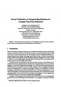
2.2.1. Task object. Among the Task object states (Figure 2.1), there are the INITIAL state and FINAL state representing respectively the state of the task before creation and the state after its deletion. A task creation (taskSpawn or taskInit VxWorks primitives) is modelled with a transition issued from the INITIAL state. The taskSpawn transition brings the task automaton straight to the READY state. The taskInit transition leads the task automaton to the SUSPENDED states (the task has then to be activated with a taskResume? transition). Due to synchronisation constraints a task may be stopped (in a PENDING,
2.1. IF Language The IF (Intermediate Format) language [4] can be viewed as an intermediate layer between high level languages such as SDL or LOTOS and mathematical models for checking such as timed automata or the LTS (Labelled Transition System). IF describes parallelism, time, and data notions easily. An IF program is built up by a set of communicating timed automata (message queues or rendez vous) or timed processes. A process is identified by its Pid (Process Identifier), a signal input message queue, a set of integers or local clock variables and a set of states and transitions linked to the process functionality. Time progress conditions are associated to states and the process stays in a given state while the condition is true. Processes evolve from one state to another by executing transitions which may require a guard for their execution, this may set new values for variables. A transition may also be waiting for a signal from another process. The transition associated actions send or receive signals or variable assignments. A variable assignment attributes an expression value to the variable or restarts a variable at an initial fixed value. Assigned data values are integer or clock type. These variables may be global and therefore be shared by the set of all the processes of an IF program. Message queues establish communication in an IF system. They are defined by a unique name and can deal with the signals in the queue between processes or between a process and the external environment. Message queues can be of several kinds: they can be bounded or unbounded, scheduled or not scheduled or with or without loss. Running the model defines the set of all the behaviours of an IF program in the form of a Labelled Transition System (LTS). The LTS generation is carried out by using the IF2C tool which performs an
2
2.2. Real-time multitasking representation using IF language
system
In this part we present the general principles of modelling, tasks, semaphores, message queues, watchdogs and fixed priority scheduler mechanisms and, lastly, duration tasks.
semGive ! / msgQSend!
taskSpawn?
INITIAL
taskSuspend?
semTake ! / msgQReceive!
PENDED
READY
semTack_ack? / msgQReceive_ack?
taskInit?
delay = 0 SUSPENDED 1
taskResume?
SUSPENDED 2 taskDelete? FINAL
taskDelay?
WAITING
taskSuspend?
Figure 2.1. VxWorks task automaton WAITING or SUSPENDED state). Due to limited space, we do not represent the WAITINGSUSPENDED and PENDING-SUSPENDED states. The automaton enters the FINAL state when the taskDelete? transition is triggered. Briefly, signals or transitions triggered by task automaton are equivalent to system calls related
to semaphores, message queues, watchdogs or ISR (Interrupt Service Routines),…etc. When a task is ‘alive’, its states are READY, PENDING, WAITING or SUSPENDED. Depending on what they are called, the system calls on semTake() ! or msgQReceive ()! which can cause the automaton of a task to enter the PENDING state. In order to bring the task back to the READY state, the task automaton model is completed with an ack_task() ? transition. 2.2.2.Communicating objects. Because they are similar, semaphore and queue message models can be presented together. Like all kernel objects, semaphore automaton and queue automaton have an INITIAL and a FINAL state (before creation and after deletion). They have also cyclic functional states called EMPTY and FULL. semTake? savePid! semTake? savePid!
semBCreate(empty) ? INITIAL
WAITING_FULL
EMPTY
semGive? semTake_ack_FirstWaintingPid!
semTake? semTake_ack!
semGive? semBCreate(full)?
semDelete?
message counting and maximum queue size using a counter and MaxMes respectively. msgQReceive(NO_WAIT)?
msgQReceive? savePid! msgQReceive? savePid!
msgQCreate ?
INITIAL
EMPTY msgQSend? counter++
WAITING_FULL
msgQsend? msgQReceive_ack_FirstWaitingpid!
counter < MaxMes msgQSend? counter++
msgQReceive? msgQReceive_ack!
FULL
FINAL
Figure 2.3. VxWorks message queue automaton 2.2.3.Watchdog. The timed automaton of the watchdog object is given in Figure 2.4. The states are INITIAL, FINAL, PASSIVE, ARMED. Once the watchdog is created with the wdCreate()? transition, the automaton passes to the PASSIVE state (state in which the watchdog object is not yet armed). wdStart(wdId,delay,pRoutine,param) ? compteur := 0
FULL
wdCancell?
FINAL PASSIVE
Figure 2.2. VxWorks Boolean semaphore automaton Semaphore (or message queue) transitions are a type of waiting signal (of type?) which are activated by a task using semBCreate? (or msgQCreate ?) or semDelete() ? (or msgQDelete). The semaphore (or message queue) model has been enriched with an additional state, WAITING_FULL, which allows the saving of the waiting task number for the semaphore, Figure 2.2 (or for the message queue, Figure 2.3). The acknowledge transition (ack) activates the pending task when the semaphore (or message queue) receives the semGive (or msgQSend) transition. First task activation (XX_ack_FirstWaitingPid) depends on the policy of the semaphore waiting queue (FIFO or by priority). The message queue is modelled with the same states as the semaphore but has some extensions for
3
semDelete?
wdCreate ?
ARMED
counter = delay pRoutine! semDelete?
INITIAL
FINAL
Figure 2.4. VxWorks watchdog automaton The transition from the PASSIVE state to the ARMED state is executed with the receipt of a wdStart signal (from a task or an alarm routine). The clock variable is then started and when it reaches a fixed time delay, the alarm routine is executed by sending pRoutine ! thereby allowing the watchdog automaton to return to the PASSIVE state.
2.2.4. Pre-emptive fixed priority scheduler. In the earlier sections, we have proposed models for the basic operating system objects. In order to take into account a pre-emptive fixed priority scheduler, these models are now completed with priority attributes. As a first approach to modelling the scheduler, we do not consider the task context switch time: we assume this time is negligible given the execution durations of the tasks.
Not-Do-Some-Thing and token=my_priority token :=my_priority +1 ACTIVE Do-Some-Thing and token=my_priority duration := 0 duration = WCET duration := 0 token := default
duration < WCET and token=my_priority duration++ token := default EXECUTION
Not-Do-Some-Thing and token=my_priority token :=my_priority +1 ACTIVE
Do-Some-Thing and token=my_priority action! token := default
Figure 2.5. Timed automaton with attributed priority task Let Ti be a task belonging to a task priority based queue waiting for the processor resource (Figure 2.5). The general ACTIVE state waits for the availability of the processor, a temporal event arrival or a triggering signal. Global token-variable is used here to model scheduling principles; this token is initialized by the highest task priority value. For example, the Ti has a token-variable giving it the highest priority. Then, two possibilities can happen. In the first one, Ti is in the READY state in which it can execute some action and reset the token-variable to the default value. In the second case, Ti is not ready and the token-variable is incremented by one and therefore gives the highest priority to the next task in the queue. Scheduling principles based on the tokenvariable are applied to other elements of the system, therefore the priority order relation of the whole system is defined as follows: priority (External environment) > priority (Interrupts) > priority (OS objects) > priority(Interrupt routines) > priority (application tasks). Task priorities can be fixed by the user. 2.2.5. Duration modelling. A duration represents the amount of time a task consumes during its execution using a processor resource, the value of this duration is supposed to be known. Figure 2.6 presents the non preempted model of task duration. The automaton passes from the ACTIVE state to the EXECUTION state; the duration variable is initialised, incremented and tested with a predefined duration value. When the value is reached, the automaton returns to ACTIVE state and releases the processor resource.
4
Figure 2.6. Not pre-emptive task automaton with duration When a priority attribute is added for preemptive scheduling, the simulation execution is controlled by the scheduler at each time unit (Figure 2.7). A task can now be pre-empted by a higher priority task in the READY state. The pre-empted task can gain the processor resource somewhat later and the simulator keeps a record of the duration. Not-Do-Some-Thing and token=my_priority token :=my_priority +1 ACTIVE Do-Some-Thing and token = my_priority duration := 0 duration = WCET duration := 0
duration < WCET duration++ E XECUTION
Figure 2.7. Pre-emptive task automaton with duration
3. Real-time verification
multitasking
model
The properties we treat may be carried out on two levels [14]: the first level checks the application elements and the second one checks the global application. In order to carry out this verification we use the notion of observer automata [13]. An observer automaton enables these properties to be checked. The observer automaton synchronizes with the system on given states and transitions. The reachability of a given control state of the observer automaton shows the existence of a given system behaviour.
3.1. Local properties 3.1.1. Abnormal system calls. Objects can only be used after their creation and before their deletion. In other cases an exception is generated. Such a case is
is used after its destruction. This WARNING state does not suspend the VxWorks system. Figure 3.3 shows an observer automaton which signals to the user the nonuse of a created object (here for example, the object taskA), created after some fixed time.
INITIAL semTake?
semGive ?
ERROR
3.1.2. Object length. The simulation of our model deals with properties which can not be verified in a static manner during compilation, like the length of the message queue. An error situation is illustrated in Figure 3.4 where the message queue length overflows. EMPTY
Figure 3.1. Observer automaton when a non created semaphore (VxWorks) is used shown in Figure 3.1 with the use of a semaphore (or message queue) before its given creation.
counter < maxMessages msgQSend ? counter ++
msgQSend ? counter := 1 counter = maxMessages msgQSend ?
FINAL msgQsend?
msgQReceive?
FULL
ERROR
WARNING
Figure 3.2. Observer automaton using a
Figure 3.4. Observer automaton of a
destroyed message queue under VxWorks The following properties must be verified: 1- Each used object must be created before it is used. 2- Destroyed objects can not be used, 3- Each created object must be used in a fixed time. 4- Each created object must be destroyed in a fixed time.
message queue of exeeded lenght under
PASSIVE taskSpawn_taskA? counter := 0
VxWorks 3.1.3Task deadlocks. The deadlock property is associated with certain pending system calls like semTake or msgQReceive. In order to avoid infinite waiting for these system calls, a timeout has been fixed on a task (Figure 3.5). An ERROR state is generated if the clock delay has reached the timeout without receiving a semTake_ack! or msQReceive_ack!. READY
counter = deadline
ACTIVE
WARNING
pendingCall! delay :=0
pendingCall_ack?
delay = timout
counter < deadline PENDING
Figure 3.3. Observer automaton of deadline of unused created task Property 1 blocks the system, the other properties do not suspend it but they affect the quality of the system. For example, when using a semaphore by activating semGive! or semTake! before its creation. (Figure 3.1), an ERROR state is reached. In Figure 3.2, a warning state is signalled with a simulation trace when, for example, a message queue
5
ERROR
Figure 3.5. Observer automaton of task timeout
3.2. Global properties 3.2.1. Time interval verification. Real time properties must be verified, such as deadline, which corresponds, for example, to take into account the minimum time to
intercept an event (see Figure 3.6) and we must take into account maximum time to stop intercepting events (see Figure 3.7).
stop_observer ? and clock < deadline
PASSIVE start_observer ? clock := 0 clock = deadline
event2 ? and clock < min_time ACTIVE event1 ? clock := 0
WAITING_ACTIVATION
PASSIVE
ERROR
ACTIVE
clock = min-time
ERROR
Figure 3.8. Observer automaton of
Figure 3.6. Observer automaton of minimum waiting time We suggest an observer automaton to check these properties. We associate clock to measure minimal time spent, by establishing WAITINGACTIVATION state which counts the time after consuming event1? which leads the system to an ERROR state if event2 was not triggered. In the same manner we conceive an observer automaton which takes into account maximum time to carry out non intercept events. Before this specific time, if event2 is triggered, then ERROR state is generated. event2 ? and clock < max-time
application deadline verification the data consumption (consume-data!). In order to validate this kind of property, an observer automaton is suggested (figure 3.9) which resets a data-age clock to some value associated to the production of data (here value-production). When the signal associated with some data is sent, it compares the data-age clock with the validity-data value. consume_data ? and data-age < validity-data
PASSIVE produce_data ? data-age := value data-age = validity-data
ACTIVE
ERROR
ERROR
event1 ? clock: = 0
PASSIVE
Figure 3.9. Observer automaton of data age ACTIVE
verification
4. Phase based graph reduction Figure 3.7. Observer automaton of maximum waiting time 3.2.2. Deadline verification. Figure 3.8 shows an observer automaton implemented for verifying deadline. The automaton is triggered by the start_observer? signal which starts the clock variable. The automaton reaches the SUCCESS state if it receives the stop_observer? signal from the application before the observer clock reaches the deadline value. Otherwise an ERROR state is generated. 3.2.3. Data age verification. The data age represents the time spent between the production (produce-data!) of the data, associated obviously with the signal, and
6
In order to deal with a state explosion of the communicating timed automata based modelling, several techniques such as abstraction [17], partial order [11] are used. In our case, we suggest phase notion [15] to model real-time multitasking application.A phase corresponds to an application functional mode with time limits. The phase possesses beginning and ending points. We consider that phases are sequentially executed for a given application. Consequently, in the case of our application, communicating timed automata model generation, the phase is characterized by initial and final states. These states represent application object states, the final state of certain phase corresponds to the initial state of the next phase. The established model may be decomposed
into phases and corresponding phase properties. In order to establish partitioning correction, it is necessary to check the following property: all paths coming from the phase initial state reach the phase final state in the simulation graph. For example, suppose that all objects and resources are fixed in a static manner and the user himself fixes the initial and final phase states. The three phases are: P1: starting phase which allows us to create objects and resources for the application, P2: permanent phase, which represents the kernel of the application characterized by cyclic functionality and P3: the third phase which ends the application by releasing all allocated resources. If we take the creation phase P1 : we obtain the following property : - INITIAL phase P1 = {element1 state = INITIAL, element2 state = INITIAL, …, elementk state = INITIAL } - FINAL phase P1 = {element1 state = ACTIVE, element2 state = ACTIVE, …, elementk state = ACTIVE} - INITIAL phase P2 = FINAL phase P1 .
5. Example This approach is illustrated by the following short VxWorks application composed of three tasks (main and two periodic tasks T1 and T2). The task main is the entry point of the application and is mandatory for the creation of the application objects. After the creation step, the task main enters the PENDING state, waiting for a semaphore called stop; when the application is finished (putting a unit in the stop semaphore), the task main deletes all the objects in the application. Each task (T1 and T2) is activated by a dedicated watchdog (WD1 and WD2). We consider that the period of WD1, resp. WD2, is equal to 5, resp. 10. A watchdog activates an alarm (RA1 and RA2) which puts one unit into a boolean semaphore (syn1 and syn2). For Processes Priorities the simulation, Watchdog WD1 1 each object Watchdog WD2 2 needs a priority Alarm routine RA1 3 Alarm routine RA2 4 level. The Counting semaphore stop 5 priority order 6 Boolean semaphore syn1 of application Boolean semaphore syn2 7 Task main 8 tasks follows Task T1 9 the classical Task T2 10 Rate Monotonic scheduling Table 5.1. Priority order of IF algorithm [9]. objects The task T1
7
has a higher priority than task T2 because of a lower period. The final priority order for all the objects is given in Table 5.1. At the end we integrate the duration of the tasks (2 time units for T1 and 4 for T2). An exhaustive simulation produces results shown Table 5.2. Phase types
states / Transtions
Observations
Complete application
919/919
Without reduction
Initial phase
12/13
Reduction using bi-simulation (Aldebaran)
Final phase
14/15
Reduction using bi-simulation (Aldebaran)
Permanent phase
103/104
Reduction by bi-simulation (Aldebaran)
Table 5.2. Simulation results The phases represent an application where certain parts are hidden. For the creation phase example, all application primitives except create_XX primitives must be hidden; the result is shown in Figure 5.2. This technique is applied to cyclic and final phases. Among the explored properties which we wish to apply, for example, to the cyclic phase, there is a deadline d2 for task T2 (with respect to Figure 2.1 task template) to be verified. After receiving activation from the watchdog WD2, the observer automaton is activated (with respect to Figure 3.8 deadline observer automaton template) by the start_observer! signal. The stop_observer! signal is sent by the task when the action is completed. Then the observer checks that the instant of the stop_observer! signal arrival happens before the instant of the start_observer! signal plus d2.
6. Extension systems
to
distributed
real-time
The suggested approach can be applied to distributed systems. Here a distributed system is viewed as a set of interconnected nodes by a dedicated network like CAN, TTP [6] … etc. The network may be used to communicate with an external environment (sensor or actuator network) or to establish communication with different nodes of the system. For the first point, [3] proposes several validation scenarios for modelling the external environment: periodic, sporadic and burst events. For the second point, if the behaviour and QoS properties of the network are wellknown (for example, the network can be modelled as a specific communicating object (section 2.2.2) with delay and may be loss rate). In the case of more complex behaviour of the network (collision,
scheduling policy for messages, …, etc.), it would be necessary to propose a specific model for the network such as that presented in [8],[12]. In any case adaptations are necessary to the proposed models. In the case of distributed systems, tasks are scheduled on each node. So we have to extend the concepts presented in section 2.2.4 adding a token-variable to each node. At each instant each node is activated in parallel. Finally the observer automata concepts may be used to model global properties of the system (for example, a deadline between two events occurring on different nodes). It is obvious that such extended models would create combinatory explosion problem. Phase notion combined with abstraction (bi-simulation equivalence [17]) seem to be good candidates to resolve this problem.
7. Conclusion Temporal verification has been carried out on the basis of a minimum platform of a real-time multitasking system consisting of operating system objects, a pre-emptive fixed priority scheduler and task duration. The observer automaton notion enables temporal application properties to be specified. Graph simulation enables temporal properties to be verified. The phase notion reduces the graph generated by partitioning the application into phases characterised by certain functions. For future research, we intend to carry out in greater depth temporal analysis by varying interruption arrivals and therefore adapt task duration. More complex cases to be chosen may give complete temporal analysis. Another perspective is to develop models for real-time distributed systems.
8. Bibliography [1] R. Allur, D.L. Dill, “A theory of timed automata”, Theoretical Computer Science. 1994, Vol. 126, pp. 183-235. [2] K. Altisen, G. Gossler, and J. Sifakis, “A methodology for the construction of scheduled systems”, In Formal Techniques in Real-Time and Fault-Tolerant Systems (FTRTFT 2000), Pune, India, September 2000, pp.106-120. [3] M. Belarbi, J.-P. Babau and J.-J. Schwarz “Temporal Validation of Real-Time Multitasking Applications Based On Communicating Timed Automata”, Forum on specification & Design Languages, FDL’04, Lille (France) 14-17 Sep. 2004. [4] M. Bozga, S. Graf and L. Mounier, “Automated validation of distributed software using the IF environment”, IEEE International Symposium on Network Computing and
8
Applications (NCA 2001), Electronic Notes in Theoritical Computer Science 55, N° 3, Cambridge, 08-10 October, 2001. [5] T. Gerdsmeier, and R. Cardell-Oliver, “ Analysis of Scheduling Behaviour using Generic Timed Automata. Computing”, The Australian Theory Symposium (CATS 2001). Electronic Notes in Theoretical Computer Science 2001, Vol. 42. [6] H. Kopetz and G. Bauer, “The time-trigerred architecture”, Proceedings of the IEEE, January 2003, Vol. 91, NO.1. [7] M.H. Klein, T. Ralya, B. Pollak and R. Obenza, “A Practitioner's Handbook for Real-Time Analysis: Guide to Rate Monotonic Analysis for Real-Time Systems”, Kluwer Academic Publishers, November, 1993. [8] J. Krakora and Z. Hanazalek, “Verifying Real Time Properties of CAN bus by Timed Automata”, FISITA, Word Automotive Congress, Barcelona, May 2004. [9] C.L. Liu, and J.W. Layland, “Scheduling algorithms for multiprogramming in a hard real time environment”, Association for Computing Machinary, 1973, 20(1), pp.4661. [10] K.G. Larsen, and P. Pettersson, Y. Wang, “UPPAAL in a Nutshell”, Journal on Software Tools for Technology Transfer, 1997, Vol. 1, N° 1-2, pp. 134-152. [11] M. Minea, “Partial order reduction for model checking of timed automata”, Proceedings of the 10th International Conference on Concurrency Theory, Eindhoven, Netherlands, August 1999, pp. 431-446. [12] H. Lonn, and P. Pettersson, “Formal Verification of a TDMA Protocol Start-Up Mechanism”, In Proceedings of the 1997 IEEE Pacific Rim International Symposium in Fault-Tolerant Systems, Taipei (Taiwan), 15-16 December, 1997, p.p 235-242. [13] Ph. Schnoebelen, “Systems and Software Verification. Model-checking Techniques and tools”, Springer-Verlag, 2001. [14] T. Szmuc, and P. Szwed, “Towards automatic correctness verification of Real-time programs”, in Appl. Math. and Comp. Sciences, 1994, Vol 4, N° 4, pp. 643660. [15] T. Szmuc , P. Szwed , J.-J. Schwarz, J. Skubich, “Hierarchical Correctness Verification in Multiphase Realtime Software Design”, IFAC/IFIP WRTP’94, 1994, pp. 87-94,. [16] J.A. Stankovic, “Misconceptions about Real-Time Computing: a Serious Problem for the Next-generation Systems”, IEEE Computer, 1988, Vol. 21, N° 10, pp. 10-19. [17] S. Tripakis, and S. Yovine, “Analysis of timed systems based on time-abstracting bisimulations”, In Formal Methods in System Design, 2001, Vol. 18, N° 1, pp. 25-68. [18] L. Waszniowski, and Z. Hanzálek, “Analysis of Real Time Operating System Based Applications”, First International Workshop on Formal Modeling and Analysis of Timed Systems, FORMATS 2003, LNCS Springer, Marseille (France), September 6-7 2003. [19] Wind River Systems, “VxWorks Reference Manual under Tornado”, 1999.