3.2, 10. Printer Controls. 3.2.11. Resetting the Terminal and Error Recovery. 3.2,
12. Trouble-shooting. 4. Graphics Terminals. 4.1. Hewlett-Packard 2623A. 4.1. 1.
ColumbiaUniversity Center for Computing Activities
Terminal and Plotter User Manual (
Janet F. Asteroff lJserServkesC;roup
(
(
Copyright IC) 1982 Columbia University Center For Computing Activities
(
Table of Contents
TABLE OF CONTENTS Introduction
1
Overview How To Use This Manual Selecting A Terminal Summary of Terminals Notes For New Users Using a Computer Terminal For the First Time A Helpful Comparison
1 1
2 2 4 4 4
1. The First Step In Using The Computer 1.1. 1.2. 1.3. 1.4.
5
Procedures Setting Up The Terminal In Theory and Practice Two Basic Rules To Follow Common and Important Terminal Settings 1.4.0.1. Special Note on Baud Rates
5 5 6
6 7
2. CRT Terminals
(
8
2. 1. Concept-APL8 2. 1. 1. Documentation 2.1.2. Turning on the Terminal 2.1.3. Setting Up the Terminal -- Configuration Mode 2. 1.3. 1. Changing the Settings 2.1.4. Completing Configuration and Clearing the Status Line 2.1.5. Resetting the Terminal 2.1.6. Optional Features 2.1.6.1. 80/132 Column Display 2.1.6.2. Reverse Video 2.1.7. Trouble-shooting 2.2. Datamedia 1520 2.2. 1. Documentation 2.2.2. Turning on the Terminal 2.2.3. Setting Up the Terminal 2.2.3.1. Switches 2.2.4. Trouble-shooting 2.3. Hewlett-Packard 2621A 2.3. 1. Documentation 2.3.2. Turning on the Terminal 2.3.3. Setting Up the Terminal 2.3.3.1. Function Key Group 2.3.3.2. Executing Terminal Functions 2.3.3.3. Step l--Changing Upper Mode Line Parameters 2.3.3.4. Step 2--Changing Lower Mode Line Parameters 2.3.4. Completing Configuration Mode and EXiting 2.3.5. Clearing and Recalling the Labels 2.3.6. The Column Counter 2.3.7. Entering Configuration Mode While Connected to the Computer 2.3.7.1. Resetting the Terminal 2.3.8. Trouble-shooting
CUCCA
Terminal And Plotter User Manual
8 8 8 8 11 12 12 12 12 13 13 14 14 14 15 15 16 17 18 18 19 19 19 20
22 22 23 23 23 23
24
November. 1982
Table of Contents
Ii
2.3.8.1. Special Problems 2.4. Hewlett-Packard National 2.4.1. Documentation 2.4.2. Setting Up the Terminal -- Configuration Mode 2.4.2.1. Changing the Straps 2.4.2.2. Lower Mode Line 2.4.3. Language Mode 2.4.4. Completing Configuration Mode and EXiting 2.4.5. Clearing and Recalling the Labels 2.4.6. Resetting the Terminal 2.5. Intertec SuperBrain 2.5.1. Documentation for File Transfer 2.5.2. Usage Policy and Scheduling 2.5.3. Operating the SuperBrain 2.5.3.1. Turning on the Terminal 2.5.3.2. Interrupting the Program 2.5.4. Using the SuperBrain as an ASCII Terminal 2.5.5. Using Floppy Disks with the SuperBrain 2.5.5.1. DEC-20 2.5.5.2. IBM 2.5.6. Notes on Floppy Disks 2.5.6.1. Storage Capacity 2.5.6.2. Purchase of Floppy Disks 2.6. Perkin-Elmer 1100 2.6.1. Documentation 2.6.2. Turning on the Terminal 2.6.3. Setting Up the Terminal 2.6.3.1. Switches 2.6.3.2. Configuration Buttons 2.6.4. Completing Configuration 2.6.5. Trouble-shooting 2.7. VT101 2.7. 1. Documentation 2.7.2. Turning on the Terminal 2.7.3. Setting Up the Terminal -- Set Up Modes A and B 2.7.3.1. Set-Up Mode A 2.7.3.2. Exiting Set-Up Mode A 2.7.3.3. Set-Up Mode B 2.7.3.4. Exiting Set-Up Mode B 2.7.4. Resetting the Terminal 2.7.5. Optional Features 2.7.5.1. 80/132 Column Display 2.7.5.2. Reverse Video 2.7.6. Trouble-shooting
24 25 25 26 26 26 27 27 27 27 28 29 29 29 29 29 30 30 30 31 31 32 32 33 33 33 34 34 36 36 37 38 38 38 39 39 39 39 40 40 41 41 41 42
(
(
43
3. Hardcopy Terminals 3. 1. DECwriter LA36 Matrix Printer 3. 1. 1. Documentation 3.1.2. Paper 3.1.3. Turning on the Terminal 3.1.4. Setting Up the Terminal 3.1.5. Trouble-shooting
43 43 45 45 45 46
( CUCCA
Terminal And Plotter User l\IIanual
November, 1982
iii
Table of Contents
3.2. Diablo 1620 Hyterm Printer 3.2.1. Usage Policy and Scheduling 3.2.2. Diablo Supplies 3.2.2.1. Print Wheels 3.2.2.2. Ribbons 3.2.3. Paper 3.2.4. An Important Warning About Diablo Usage 3.2.5. Before Turning on the Terminal 3.2.6. Setting Up the Terminal 3.2.6.1. Inside Control Panel 3.2.7. Changing the Baud Rate 3.2.8. Turning on the Terminal 3.2.8.1. Right Control Panel--Red Rocker Switches 3.2.8.2. Left Control Panel 3.2.9. Impression Control Switch 3.2, 10. Printer Controls 3.2.11. Resetting the Terminal and Error Recovery 3.2,12. Trouble-shooting 4. Graphics Terminals
55
4.1. Hewlett-Packard 2623A 4.1. 1. Documentation 4.1.2. A Special Note on Baud Rates 4.1.3, Turning on the Terminal 4.1.4, Setting Up the Terminal -- Configuration Modes 4.1.4,1. Terminal Configuration Mode 4.1.4.2, Saving the Settings and Exiting 4.1.4,3. Datacomm Configuration Mode 4.1.4.4. Saving the Settings and Exiting 4.1.4,5. Graphics Mode 4. 1.4.6. Resetting the Terminal 4.1.5. Trouble-shooting 4.2. Hewlett-Packard 7221 S Graphics Plotter 4.2.1. Documentation 4.2.2. Plotter Supplies 4.2.2.1. Pens 4.2.2.2, Paper 4.2.3. Turning on the Plotter 4.2.4. Setting Up the Terminal 4.2.4.1. Manual Control 4.2,5. Trouble-shooting 4.3. Tektronix 4013 4.3.1. Documentation 4.3.2. Turning On the Terminal 4.3.3. Setting Up the Terminal 4,3.3.1. Knobs 4,3.3.2, Switches 4.3.4. Clearing the Screen and Resetting the Terminal 4.3.5. Trouble-shooting 4.4. Tektronix 4631 4.4,1. Trouble-shooting 4.4.2. Graphics Software
CUCCA
47 47 48 48 48 48 48 49 49 49 51 51 51 52 52 52 53 53
Terminal And Plotter User Manual
55 56 56 56 56 57 57 57 58 58 58 59 60 60 60 60 61 61 61 62 64 65 65 66 66 66 67 67 67 68 69 69
November, 1982
iv
Table of Contents
5. Terminal Repair and Installation Procedures
70
5.1. Terminal Problems 5. 1. 1. Reporting to Systems Assurance 5.2. Purchasing A Terminal
70 70 70
Glossary and Abbreviations
71
Appendix I. DEC WS78 and DECMATE Word Processors
73
1.1. Setting Up the Word Processor 1.2. The IBM Systems Preparing to Log in 1.3. DEC-20 System 1.4. Returning to the Word Processor Trouble-shooting
(
73 73 73 74 74 74
Appendix II. Solving Common Problems
75
Appendix III. HP 2621A and HP 2621 National Summary
76
Index
77
(
( CUCCA
Terminal And Plotter User Manual
November, 1982
v
List of Photographs
LIST OF PHOTOGRAPHS Photograph Photograph Photograph Photograph Photograph Photograph Photograph Photograph Photograph Photograph Photograph Photograph Photograph Photograph Photograph Photograph Photograph Photograph Photograph Photograph Photograph Photograph Photograph Photograph Photograph Photograph Photograph Photograph Photograph
CUCCA
2-1: 2-2:
2-3: 2-4:
2-5: 2-6: 2-7: 2-8: 2-9: 2-10: 2-11: 2-12:
2-13: 2-14: 2 - 15:
2-16: 3-1: 3-2: 3-3: 3-4: 3-5: 3-6: 4-1: 4-2: 4-3: 4-4: 4-5: 4-6: 4-7:
Concept-APL8 Concept-APL8 Keyboard Concept APL-8 Cursor Control Pad and Numeric Pad Datamedia 1520 Datamedia Switches Datamedia Keyboard Hewlett-Packard 2621A Hewlett-Packard 2621A Keyboard Hewlett-Packard Function Key Group Hewlett-Packard National I ntertec SuperBrain Perkin-Elmer 1100 Perkin-Elmer Switches and Logo Plate Perkin-Elmer Keyboard and Configuration Buttons VT101 VTf01 Set-Up Card ~M
LA36 Keyboard LA36 Switches Diablo 1620 Diablo 1620 Keyboard Diablo Inside and Right Control Panels Hewlett-Packard 2623A Hewlett-Packard 2623A Keyboard Hewlett-Packard 7221S Graphics Plotter Hewlett-Packard 7221S Front Control Panel Tektronix 4013 Tektronix Knobs Tektronix 4631
Terminal And Plotter User Manual
9 9 10
14 15 16 17 18 18 25 28 33 35 35 38
41 43 44 44 47
49 50
55 56 60 62 65 66 68
November, 1982
vi
List of Figures
LIST OF FIGURES Figure Figure Figure Figure Figure Figure Figure Figure Figure
2-1: 2-2: 2-3:
2-4: 2-5: 2-6: 2-7: 2-8: 2-9:
Concept-APL Mode Line Hewlett-Packard 2621A Upper Mode Line Labels Hewlett-Packard 2621A Lower Mode Line Labels Hewlett-Packard National Upper Mode Line Labels Hewlett-Packard National Lower Mode Line Labels Hewlett-Packard National Language Mode Perkin-Elmer 1100 Settings VT101 Set-Up Mode B--Four Left Fields VT101 Set-Up Mode B--Three Right Fields
( 8 20 20 26 26 27
34 40 40
(
( CUCCA
Terminal And Plotter User Manual
November, 1982
vii
List of Tables
LIST OF TABLES Table 1-1: Table 2-1:
CUCCA
IBM 4341 and DEC-20 Settings Hewlett-Packard 2621A Value Settings
Terminal And Plotter User Manual
6
20
November, 1982
(
(
(
Introduction
INTRODUCTION OVERVIEW The Terminal And Plotter User Manual explains how to operate the public computer terminals and graphics plotters made available by CUCCA (Columbia University Center for Computing Activities). This manual will help you select the terminal which best suits your needs, and once having done so, operate it successfully; no knowledge of computing or computer terminals is required. Included for those who have never used a computer terminal before are special introductory sections as well as a glossary. For advanced users, general technical information and terminal settings are provided for reference. In addition to the sections on public terminals, instructions are included for using the DEC WS78 and DECMATE word processors as ASCII terminals to connect to the IBM 3031, 4341, and DECSYSTEM-20 computers. Privately purchased, these word processors are located in many administrative and academic offices; they are not made available by CUCCA. Information about the word processors is presented in Appendix I. Non-technical information relating to terminal usage and availability is detailed in the CUCCA GUide To Research and Instructional Facilities and the Newsletter, both available in the Reference Room in the SSIO (Self-Service Input-Output) area (see immediately below for location). Similarly, for instructions on how to establish communications with the computer 1I0gging in), please refer to the IBM 4341 Log In Procedures sheet or the DECSYSTEM-20 Reference Card, both available in the Reference Room. Software for setting up many terminal features is explained in the DEC-20 Reference Card, the IBM 4341 Wylbur Manual and the CMS Wylbur Technical Note. Copies of the Terminal And Plotter User Manual are available in the Reference Room, 1 15A, in the SSIO area located in the basement of Uris Hall, or by calling 280-4330.
HOW TO USE THIS MANUAL Chapter 1, The First Step In Using The Computer, is extremely valuable for new users, and more advanced users can reference the information about terminal settings as needed The remaining chapters are divided by category: crt terminals, hardcopy terminals and graphiCS terminals. Each section contains the technical information you need to use the terminals, and provides a reference to vendor manuals. Particularly, the subsection SeWng Up the Terminal, included for every terminal, tells you precisely how to use that terminal for either the IBM or DEC-20 systems. A subsection on specific problems, Troubleshoot/ng, outlines the common problems which you might encounter while using a specific terminal. Also included is a chapter on repair and installation procedures, an appendix on common terminal problems and their remedies, and a summary of Hewlett-Packard terminal information. The Table of Contents is very specific, and can refer you directly to the section you need. If you want to know something very specific and very quickly. e.g., how to
CUCCA
Terminal And Plotter User Manual
November, 1982
2
Introduction
change the parity on the Concept APL-8 terminal, please check the index under the logical headings, in this case either "Concept-APL, Parity, changing" or "Parity, Concept-APL."
(
SELECTING A TERMINAL Choosing a terminal depends on need and availability. Crt (cathode ray tube) terminals are best for programming, text entry and editing, and can print at higher baud rates (speeds) than hardcopy terminals. Crt terminals have screens similar to a television screen, and are also referred to as vdt's (video display terminals), although there are some differences. Hardcopy terminals have print elements but do not have screens, and are used for printing output, either text or graphics, although they also can be used for programming and editing. Some terminals combine both video and printing features. Graphics terminals often have both a video screen and a hardcopy capability. Some hardcopy units are independent of the crt, some are attached. All CUCCA terminal keyboards have upper and lower case. CUCCA also provides terminals with APL character sets, and terminals specifically for graphics. All the terminals described in this Manual can be used with both the DECSYSTEM-20 and IBM 4341 computers.
SUMMARY OF TERMINALS New terminals are continually being installed on the Morningside campus. The list provided below presents a brief description of those currently available. Further explanations, information about availability, restrictions, or special equipment are provided in the specific sections.
(
( CUCCA
Terminal And Plotter User Manual
November, 1982
Introduction
3
TERMINALS AND PLOTTERS CRT
HARDCOPY
1. Hewlett-Packard 262 1A. The 2621 A offers a large range of special functions. It is widely used at CUCCA. 2. Hewlett-Packard 2621 AlP (National), The same as the HP 2621 A with additional natural language features for international use. 3. Concept-APL8. An APL character set is available, as is hardware windowing for use with EMACS on the DEC-20. The Concept APL8 also has a 132 column display capability. 4. Perkin-Elmer Fox 1100. An older terminal without an APL character set. 5. Datamedia 1520. An older terminal with an APL character set. 6. Intertec SuperBrain, A microcomputer used primarily for transferring files from the IBM 4341 and the DEC-20 to floppy disks, Scheduling for use. 7. VT 10 1. Manufactured by the Digital Equipment Corporation, the VT 10 1 has a detachable keyboard and 132 column display capability, 8, Hewlett-Packard opposite,
2623A.
See
9. Tektronix 4013 (Graphics!. A graphics terminal with vector graphics capability, ASCII and APL character sets are available, Used in conjunction with the 4631 hardcopy unit (see opposite),
CUCCA
1. DECwriter (Matrix). The most widely used hardcopy terminal at CUCCA, it is a dot matrix printer (not letter quality) which allows you to make a record of your session or print output. The DECwriter uses 1 1x 14 output paper and can accommodate narrower widths. 2, Diablo 1620 (Daisy). A letterquality printer to produce final copies of essays, reports, dissertations etc. Prints in 10 or 12 pitch, Wheels and ribbons must be purchased, Scheduling for use. 3, Tektronix 4631 (Graphics), The hardcopy unit used in conjunction with the 40 13 crt. The 4631 prints the crt image, 4. Hewlett-Packard 2623A (Graphicsl, The 2623A has a built-in heat copier capable of printing both the alphanumeric and the graphics memory. Scheduling for use. 5, Hewlett-Packard 7221 S (Plotter). Four-color graphics pen plotter with vectors, rotation, scaling and clipping facilities. Paper is available but pens must be purchased. Scheduling for use. 6, Gould 5100 (Plotter), The Gould electrostatic plotter is currently available only through operator service for the IBM 4341. It is not described in this manual. Please consult the Gould Technical Note available in the Reference Room for information on usage.
Terminal And Plotter User Manual
November, 1982
Introduction
4
NOTES FOR NEW USERS
(
CUCCA offers several kinds of computer terminals to meet different needs. The preceding paragraphs should familiarize you with the facilities. However, if you have never used a computer terminal before, a few points might make your adjustment easier and thus expedite your work,
USING A COMPUTER TERMINAL FOR THE FIRST TIME If you have never used a computer terminal. it is best that someone show you the basics. Consultants are available in the 5SI0 area and in Room 272A Engineering Terrace to answer your questions and instruct you in the operation of the terminals. However, you may wish to take instructions directly from the Manual.
A HELPFUL COMPARISON For many new users, the sight of the computer terminal keyboard immediately brings to mind a typewriter. This is particularly true of hardcopy terminals, which have print elements instead of screens. The terminal keyboard closely resembles the keyboard of an electric typewriter. The alphabetic and numeric arrangements are identical. although some Backspace, caps lock, and shift keys terminals have separate number pads as well, perform the same function as on a typewriter. The carriage return key is located on the right-hand side of the second bank of keys, as it is on an electric typewriter, and performs roughly the same function, For further explanations of these keys as they relate to typewriters and terminals, see the Concept 108 Users Manual pps. 1-4: 1-6, available in the Reference Room in the SSIO area.
(
( CUCCA
Terminal And Plotter User Manual
November, 1982
5
The First Step In Using The Computer
CHAPTER 1 THE FIRST STEP IN USING THE COMPUTER
1.1. PROCEDURES The procedures for using the computer, listed in order of occurrence, are as follows: 1. Set up the terminal.
2. Turn on the PACX box and make a connection to the system. 3. Log in. 4. Do your work. 5. Log out. This chapter presents comprehensive information about point 1.
1.2. SETTING UP THE TERMINAL IN THEORY AND PRACTICE The first step in using most computer systems is to make sure that your terminal is set up or "configured" for the system you will be using. This includes setting baud rate (terminal speed!. parity, duplex and other parameters. (See the Glossary on p. 71 for definitions of these terms.) There are three distinct aspects to consider when configuring your terminal: 1. The IBM and DEC-20 systems require different values for certain settings, e.g., parity. duplex etc.
2. Each terminal differs in the kinds of settings which are available and have to be changed, although most terminals do share some common settings (see below, section 1.4). For example, not all terminals have a handshake parameter, but many have a duplex parameter. In short, different terminals have different features; what you must change on one will not necessarily be present on another. This will become clear after you have used at least two different makes of terminals. 3. Each terminal differs in the physical manner in which these values are established, i.e" older terminals tend to have switches and buttons, while the newer terminals take typed-in sequences.
CUCCA
Terminal And Plotter User Manual
November, 1982
6
The First Step In Using The Computer
1.3. TWO BASIC RULES TO FOLLOW
(
1. Turning on the terminal is the first step in using one; it must be turned on before it can be configured. If you do not hear a beep or the screen brighten after a minute to signify it is powered on, the terminal may be out of order, although you should check to see that the brightness is turned up and that the unit is plugged in. For hardcopy terminals you may physically feel that the power is on if there are no indicator lights, but usually the print element moves slightly to signal power on. 2. You should configure your terminal for the proper system before making a connection with the computer through the PACX Gandalf blue box located near the terminal. Some systems will not recognize changes in settings once you have logged in, although others will. For PACX information see the 4341 Log In Procedures sheet or the DEC-20 Reference Card.
1.4. COMMON AND IMPORTANT TERMINAL SETTINGS No matter what terminal or system you are using, you should be aware of the following three parameters. Please note however that when using graphics terminals and plotters, certain values must be synchronized with the host terminal. (Baud rates are subject to change. See below the special note on baud rates, section 1.4.0.1 for further information.) 1. Baud Rate. The speeds appear as 300; 1200; 1800; 4800; 7200; 9600.
(
2. Parity. Parity value names differ for each terminal. but should generally be set to none for both systems, although some terminals equate mark with none. Please check each section for the choices. 3. Duplex. The settings will always appear as half or full. The current values for these settings are:
SETTINGS
DEC-20
IBM 4341
Baud Rate Parity Duplex
4800 None' Full
1800 None' Half
Table 1-1:
IBM 4341 and
DEC-20 Settings
• The equivaient of Mark on some terminals.
( CUCCA
Terminal And Plotter User Manual
November, 1982
The First Step In Using The Computer
7
1.4.0.1. SPECIAL NOTE ON BAUD RATES The speeds indicated above are the maximum that PACX. not hardwired terminals, can comfortably support. Development work is currently underway to allow a higher baud rate for the IBM systems. But at present, 1BOO is the maximum baud rate for terminals connected through the PACK Users also should note that individual crt's may have built-in restrictions and therefore may not be capable of operating at the maximum speeds listed above. Hardcopy Baud Rates Unless otherwise indicated, CUCCA's hardcopy terminals must be run at speeds of 300 baud or lower. Graphics Terminals and Plotters The HP pen-plotter can be run only at 1200 baud or lower. All other graphics terminals may be run at the specified baud rate for that system. But the baud rate must be synchronized with the host terminal. Consult the individual sections.
CUCCA
Terminal And Plotter User Manual
November, 1982
8
Concept-APl8
CHAPTER 2 CRT TERMINALS
(
2.1. CONCEPT-APL8 The Concept-APl8 terminal is a microprocessor-based terminal which offers an APl character set and advanced features such as hardware windowing. which are well supported by EMACS on the DEC-20. The Concept-APl8 also has a 132 column display capability.
2.1.1. DOCUMENTATION Copies of the Concept Manual and Reference Card are available in the Reference Room in SSIO.
2.1.2. TURNING ON THE TERMINAL The ON/OFF switch for the Concept is located In the rear center of the terminal. It should be pressed to the left to turn on the terminal. The brightness knob is located on the left side of the terminal under the screen housing. Turn it counterclockwise to brighten the display.
(.
2.1.3. SETTING UP THE TERMINAL -- CONFIGURATION MODE RESET/STAT Key The Concept uses typed-in characters rather than switches to set its operation modes. After turning on the terminal. press the RESET/STAT key on the Cursor Control Pad on the upper right side of the keyboard (see photograph 2-3). This will display the inverse video status line (white background with dark lettering), across the bottom of the screen. The status may display many different values. Following is a mode line configured for the DEC-20: KB 4800 FUll lSTOP NONE/OFF REM PROG CHAR Figure 2-1:
U/l 047:003 ASC 000,000,048.080 F0100
Concept-APL Mode Line
( CUCCA
Terminal And Plotter User Manual
November, 1982
9
Concept-APL8 Photographs: Peter Sprung
Photograph 2-1:
Photograph 2-2:
CUCCA
Concept-APi8
Concept-APL8 Keyboard
Terminal And Plotter User Manual
November, 1982
Concept-APL8
10
Note: Unlike some other terminals, the Concept APL does not display the names of the settings, only the values, i.e" 4800 in the second field above refers to baud rate.
(
You need not be concerned with all the fields displayed on the mode line. The instructions below correspond to the mode line, reading from left to right. Important settings are noted in italics.
(
Photograph 2-3:
Concept APL-B Cursor Control Pad and Numeric Pad
(
CUCCA
Terminal And Plotter User Manual
November, 1982
11
Concept-APL8
2.1.3.1. CHANGING THE SETTINGS The MULT CODE Key The values of the settings are changed by issuing MULT CODE character sequences, That is, each sequence is prefaced by pressing the MULT CODE key located on the Cursor Control Panel on the upper right side of the keyboard. You press it only once with regular pressure, and do not hold it down, Unfortunateiy, nowhere is it indicated that the MULT CODE has been depressed, In MULT CODE sequences, the case of the ietters is extremely important Often a feature is enabled or disabled depending on the case of the letter, i,e" upper or lower case, In the following. unless the word shift precedes a letter, be sure to use the lower case or unshifted form, Shift indicates that you enter a capital letter by depressing the shift key; If you do not change the setting as desired on the first try, you must begin the entire sequence over again, I.e., by depressing the MULT CODE key again, followed by the proper command, The MULT CODE key cannot be depressed repeatedly to achieve the desired setting, NOTE: Before attempting the following, you must place the terminal in Programmer Mode, which is included in the list below, by pressing MULT CODE Shift U, Otherwise, the MULT CODE .sequences will have no effect. Important settings are in italics,
(
,
KB
Keyboard mode, If set RESET/STAT key twice,
to
anything
BAUD RATE
Symbols such as % and ( are used for setting the baud rate, The Concept keyboard is an APL keyboard, so to quickly find these symbols you should look on the front of the numeric keys, not on the top of the numeric keys, as is the case with most keyboards, To change the baud rate press: (capital letter 0), followed by:
%
*
300 1200 1800 2400
+
but
KB,
press
the
MULT CODE Shift 0
3600 4800 9600
DUPLEX
For IBM (half) enter MULT CODE Shift 8; for DEC-20 (full) enter MULT CODE 8 ,
STOP
Should be set to 1STOP for speeds over 300; MULT CODE Space < ", (Space means press the space bar,)
PAR/TY
Set to NONE/OFF for all systems; MULT CODE Shift P Space,
REM/WC
Must always be set to REMOTE computer, MULT CODE 9,
CUCCA
Terminal And Plotter User Manual
in
order
to use the
November. 1982
12
Concept-APL8
PROG
Programmer mode. MULT CODE Shift U. Can also be set to User mode by MULT CODE u, but you cannot configure the terminal in user mode.
CHAR
Should always be set to CHAR. If not, press MULT CODE 7.
U/L
Upper and lower case letters. MULT CODE % for upper case; MULT CODE 5 for upper and lower case.
CURSOR POSITION
Indicates the position of the cursor on the screen.
ASC/APL
To enable for APL, MULT CODE 0 (numeral). To disable and return to ASCII for regular use, MULT CODE SHIFT O.
(
The Numeric Keypad -- An Easy Way to Setup the Terminal Note that some of the settings are clearly displayed on the Numeric Pad on the right side of the keyboard (see photograph 2-3). For instance, "8" corresponds to Duplex, "9" to Local/Remote, "5" to upper!lower case, and "0" to ASCIi/APL. Those markings on the top half of the keys indicate that you use them in shifted mode, i.e., while depressing the shift. You may use these numeric keys after typing a MULT CODE instead of the numeric keys on the top row of the regular keyboard.
2.1,4. COMPLETING CONFIGURATION AND CLEARING THE STATUS LINE
(
You are now ready to use the computer. You can clear the status line by pressing the RESET/STAT key. Recall the status line by pressing the RESET ISTAT key again.
2.1.5. RESETTING THE TERMINAL Resetting the terminal puts it back to the state it was in when it was first turned on. Press Shift RESET/STAT simultaneously.
2.1.6. OPTIONAL FEATURES 2.1.6.1.80/132 COLUMN DISPLAY You may vary the display width between 80 columns, which is the default, and 132 columns, for typeout or editing. The change to 132 columns, enter the sequence MULT CODE " (quotation marksl. To return to 80 columns, enter MULT CODE ! (exclamation point!.
( CUCCA
Terminal And Plotter User Manual
November, 1982
Concept-APL8
13
2.1.6.2. REVERSE VIDEO The Concept APL has a reverse video mode that is very easy to set. Most terminals offer only white characters on a dark background. This is the default for the Concept, but you can also invoke reverse video mode, Le., dark characters on a white background. Do this by pressing MULT CODE Shift D. Adjust the brightness with the knob on the left under side of the screen. Turn off the reverse video, that is, go back to normal video, by pressing MULT CODE d. It is not a part of the standard configuration procedure; it does not appear on the mode line nor does it affect the operation of the terminal.
2.1.7. TROUBLE-SHOOTING Problem
Cause/Remedy
No Power
If you accidently turn off the terminal in the middle of a session, the terminal will revert to the settings it had when first turned on. Your program should be intact, but you may have to reconfigure the terminal. Press carriage return or refresh the screen. No power or a loss of power will also occur if the unit is not plugged in. Check the power cord. If the terminal is plugged in and powered on and there still is no power, the fuse may have blown. Report the condition to Systems Assurance, ext. 3100.
Dark Screen
If you cannot see the cursor on the screen, the brightness knob is turned all the way down. Turn counterclockwise until cursor appears or screen lightens. If this does not work, see below "Strange" Modes.
Upper Case Only
Make sure U/C button on left is unlit; depress to turn off light. Check the status line to indicate U/L and not CAP.
Computer Does Not Respond
Check to see that Remote and not Local is enabled.
INSRT Mode Enabled
Insert Mode. The light will be lit. This may cause disruption of text, especially while using EMACS on the DEC-20. To disable, reset the terminal; see above.
"Strange" Modes
Unspecific symptoms include buzzing, strange patterns on the screen, a missing cursor, bright vertical lines etc. Turn off the terminal for about 10 seconds, and turn it back on. You may need to reconfigure the terminal.
CUCCA
Terminal And Plotter User Manual
November, 1982
14
Datamedia 1520
2.2. DATAMEDIA 1520
(
The Datamedia 1520 has an APL character set. It has baud rates of 300. 1800 and 4800. The Datamedia has been locally modified to allow a 4800 baud rate.
2.2.1. DOCUMENTATION The Datamedia 1520 manual is available in the Reference Room in the 5510 area.
2.2.2. TURNING ON THE TERMINAL The ON/OFF switch is located on the right rear side of the screen housing. The positions are clearly marked; push the switch on the top to turn on the terminal. To focus the screen first rotate the brightness knob, and then the contrast knob on the lower right hand side of the casing (both are clearly marked). The volume of the belt can also be adjusted by rotating the knob located on the right side of the keyboard.
(
Photograph 2-4:
CUCCA
(
Datamedia 1520
Terminal And Plotter User Manual
November, 1982
15
Datamedia 1520
2.2.3. SETTING UP THE TERMINAL 2.2.3.1. SWITCHES The front panel of the Datamedia 1520 has the following 8 switches which should be depressed to record settings. When you want to change a setting push all the way in and release. Labels have been placed on the buttons to indicate their functions. The sixth and seventh buttons (those not markedl are inoperative. Important settings are in italics. TAPE
Place in OUT POSITION at all times.
DUPLEX
IN for Full Duplex for the DEC-20; OUT for Half Duplex for the IBM.
DATA RATE
IN for all systems. When the Data Rate is OUT a 300 baud rate is established.
EIA
IN position at all times.
ASCII
IN for ASCII alphanumerics; OUT for APL character set.
LAST (8th) BUTTON
IN for 4800; OUT for 1800 for baud.
Photograph 2-5:
CUCCA
Datamedia Switches
Terminal And Plotter User Manual
November. 1982
Datamedia 1520
16
2.2.4. TROUBLE-SHOOTING Problem
( Cause/Remedy
No Power
If you accidently turn off the terminal in the middle of a session, turn it back on; all the settings will remain. Your program should also be intact. Press carriage return or refresh the screen. No power or a loss of power will also occur if the unit is not plugged in. Check the power cord. if the terminal is plugged in and powered on and there still is no power. the fuse may have blown. Report the condition to Systems Assurance, ext. 3100.
Dark Screen
The brightness knob is not adjusted correctly; turn clockwise until screen lightens.
No Bell
The volume is turned all the way down. Adjust the knob.
"Strange Characters"
Either the TAPE or the TAPE LOAD buttons have been depressed. Make sure both are released (out). Also. check to see that the ASCII button is in.
(
Photograph 2-6:
Datamedia Keyboard
( CUCCA
Terminal And Plotter User Manual
November. 1982
Hewlett-Packard 2621 A
17
2.3. HEWLETT-PACKARD 2621A The HP 2621 A offers an attractive character set and a large range of special functions which give it the versatility necessary for use with much of the software currently available at Columbia. For a summary of instructions about the HP 2621 A and HP2621 National terminals. please see Appendix III, p. 76
(
Photograph 2-7:
Hewlett-Packard 2621 A
PLEASE NOTE
The HP 2621 A and the HP 2621 AlP National terminals are physically identical, but they have slightly different settings. Still. almost all of the information listed in this section applies to the HP National as well. and thus is not repeated in that section. Currently. most of the HP National terminals are located in the Carman terminal room. although this may change. The easiest way to determine which terminal you are using is to enter Configuration Mode (see beiow section 2.3.3 p. 19) and examine the lower mode line. If LANGUAGE instead of EX I T appears in the left most setting of the lower mode line it is a National terminal. The mode lines are the white blocks with dark lettering which appear at the top and bottom of the screen. Check p. 20 to see the mode line for the HP 2621A Also, check the Straps parameter on the upper mode line. If it does not appear exactly as specified on p. 20, i.e.. the National has an "a" in the field on the upper mode line, see below. 2.4. p. 25.
CUCCA
Terminal And Plotter User Manual
November, 1982
Hewlett-Packard 2621 A
18
2.3.1. DOCUMENTATION
(
Copies of the HP 2621 A Owner's Manual are available in the Reference Room and the consultant's offices in the SSIO area and Room 272A Engineering Terrace.
2.3.2. TURNING ON THE TERMINAL The ONIOFF switch for the HP 2621 A is located on the bottom right hand side on the back of the terminal. It is a wide black rocker switch which should be pushed to the right to turn on the power. The brightness and contrast are preset and should not be changed.
(
Photograph 2-8:
Hewlett-Packard 2621A Keyboard
DDlEIlDII Photograph 2-9:
CUCCA
(
Hewlett-Packard Function Key Group
Terminal And Plotter User Manual
November, 1982
Hewlett-Packard 2621 A
19
2.3.3. SETTING UP THE TERMINAL 2.3.3.1. FUNCTION KEY GROUP The Function Key Group consists of eight Function Keys located across the top of the keyboard (as illustrated opposite), and the Labels Key (the only blank key). located to the right above the carriage return. These keys are used in a shifted mode, i.e., while holding down the shift key, to configure the terminal for a given computer system. When the keys are used without the shift key, they control cursor and scrolling functions. When using these keys to configure your terminal. the computer has no knowledge that the cursor has been moved. You cannot use these keys to position the cursor when using an editor, e.g., EMACS. After the terminal is turned on, eight labels--the Primary Labels--will appear along the bottom of the screen. Each label corresponds to one of the eight function keys located along the top of the keyboard. There are six different sets of labels that may appear, depending upon what mode the terminal is in. For the HP 2621A however, we will discuss only two sets, the Primary Labels and the Configuration Mode Labels. Note: When depressed, the Labels key calls back the primary labels, no matter what mode you are in.
2,3.3.2, EXECUTING TERMINAL FUNCTIONS Each of the labels along the bottom of the screen names a terminal function that you may execute to achieve a desired effect. There is a one-to-one correspondence between these labels and the function keys larrows) on the top of the keyboard. The functions are executed by pressing the corresponding function key while holding down the shift key. When the terminal is turned on, the Primary Labels are initially displayed. In order to set the values of various configuration parameters. you must put the terminal into Configuration Mode. NOTE: It is impossible to enter Configuration Mode unless the Primary Labels are currently displayed. At any time you may recall the Primary Labels by pressing the Labels key, the blank key on the right.
a
To enter Configuration Mode. hold down the shift key while pressing the key. Parameter labels and values will appear along the top of the screen. and the bottom labels will change to the Configuration Mode labels. The labels for the upper mode line are displayed as follows for the DEC-20:
CUCCA
Terminal And Plotter User Manual
November, 1982
Hewlett-Packard 2621 A
20
Baud Rate 4800
Parity NDNE(O)
Figure 2-2:
Duplex FULL
Straps bCGHxz
Handshake etx
Hewlett-Packard 2621A
Hz 60
Start Col 1
Return [or 1
(
Upper Mode Line Labels
Only those values below in italics should be changed. The recommended values for the configuration parameters are: SETTING
DEC-20
IBM 4341
Baud Rate Parity Duplex Straps Handshake
4800 NONE(OJ
1800 NONE(1)
Hz
Full bCGHxz etx 60
Start Col Return
[cr ]
Half bcGHxz etx 60 1 [cr ]
Table 2-1:
,
Hewlett-Packard 2621A
Value Settings
(
The lower mode line will also be displayed: EXIT
NEXT
PREVIOUS
Figure 2-3:
MODM OFF
REMOTE*
CAPS LK
LN MODE
AUTO LF
Hewlett-Packard 2621A Lower Mode Line Labels
Note: Only the REMOTE function is enabled 1*1. See below 2.3.3.4. p. 22.
2.3.3.3. STEP 1--CHANGING UPPER MODE LINE PARAMETERS Change the values if they do not conform to the above chart. This is very easy to do. and once you have changed one parameter. you wiil understand how to change the remainder. First select the parameter that needs to be changed. i.e., baud rate. parity etc. Do this by positioning the cursor under the proper field using the I:lI and £:II keys on the upper right side of the keyboard, unshifted, that is, without pressing the shift key. Each parameter is changed by pressing the shift and the the _ key.
CUCCA
!I
Terminal And Plotter User Manual
key andlor the shift and (
November. 1982
Hewlett-Packard 2621 A
21
IIi3 or E:II keys to Once the parameter is changed to the proper value, press the move to the next field and repeat the procedure. Those parameters in italics are different for each system.
BAUD RATE
To
change the baud rate, press the shift and the key. Once may not be enough however to get the proper value. To change the value again, continue to press the elII key while holding down the shift until the desired value appears. In other words, don't remove your finger from the shift key, but continue to press the elII key. The elII key returns higher values. The _ key returns lower values. You can use either one.
elII
PARITY
The parity is changed in the same manner as the baud rate. After positioning the cursor to the proper location, press the shift and elII key until the proper setting appears. For the IBM 4341 the setting is NONE( 11 and for the DEC20 NONE(O).
DUPLEX
Same as above. For the DEC-20 it is set to Full, for the 4341 to Half.
STRAPS
Straps operate slightly differently, since the cursor is positioned under each letter instead of the entire field. If one of the letters is not in the correct case, you must change it by moving the cursor underneath the letter that must be and E:II keys unshifted), and changed (using the IIi3 then pressing the shift and elII key.
HANDSHAKE
Handshake works the same as Straps. If the current Handshake setting is eTx, and you must change this to etx, do the following. First, position the cursor under the T in eTx by using the IIi3 and/or E:II keys. Then press shif t elII. The upper case T will change to a lower case t, leaVing the Handshake parameter with the value, etx.
Hz
Should not be changed if set to 60. If it is not set properly, change in the same manner as indicated above.
START COL
Should not be changed if set to 1. If it is not set properly, change in the same manner as indicated above.
RETURN
This generally should not be changed However, if it is ever anything other than [cr 1 you may change it as follows: First position the cursor so that it is immediately to the right of the left bracket L using the IIi3 and/or E:II keys. Then press the RETURN key followed by the SPACE bar.
CUCCA
Terminal And Plotter User Manual
November, 1982
22
Hewlett-Packard 2621 A
2.3.3.4. STEP 2--CHANGING LOWER MODE LINE PARAMETERS
(
The last four labels in Configuration Mode control the settings of four modes. Each mode is either enabled (on) or disabled (off). When a particular mode is enabled, an asterisk * will appear inside the label box. To change the state of one of these modes, you use the E:lI ,and 0 in shifted mode. right-hand side function keys 0
,a ,
The modes should be set as follows. Those in italics should be noted.
REMOTE
This mode MUST be enabled if you wish to communicate with any of the computers at Columbia. To enable Remote press shift 0 and the * will appear. Often this mode is accidently disabled, and users think that the terminal is broken or the line is bad. Please check to see that this function is enabled before reporting the terminal or line out of order. To disable the Remote mode, simply repeat the same function, i.e., press the 0 again while holding down the shift key.
CAPS LK
When this mode is enabled all lower-case aiphabetic characters typed .at the keyboard will be transmitted to the computer as the corresponding upper-case characters. An * will appear in the corresponding label to signify it is enabled. To disable CAPS LK, press shift and the asterisk should disappear. To enable, simply repeat the function. Non-alphabetic keys are not effected, and no characters received from the computer are translated.
a
LN MODE
If it is This is a special mode that should be disabled. accidently enabled, press shift E:lI to disable it. If enabled. you cannot connect to the computer.
AUTO LF
This mode should generally be disabled, but may be enabled as a convenient method for typing out a piece of text with double spacing. To enable, press shift 0
MODM OFF
This function systems.
has
no
effect
on
any
of
the
(
Columbia
2,3.4. COMPLETING CONFIGURATION MODE AND EXITING Once the parameters are properly set, you may exit Configuration Mode. The EXIT function is used to restore the screen to the state it was in before entering Configuration Mode and display the Primary Labels at the bottom of the screen. To exit, simply repeat the function for entering, i.e., press shift ~ The top labels will disappear. You may also exit by pressing the Labeis key. Use the Labeis key if some other mode is accidently selected. You are now ready to make a connection with the computer.
( CUCCA
Terminal And Plotter User Manual
November, 1982
23
Hewlett-Packard 2621 A
2.3.5. CLEARING AND RECALLING THE LABELS If you do not wish to see the Primary Labels while you are using the computer, hold down both the shift and Control (ctrl) keys while pressing the Labels key; the labels will disappear. To bring back the labels, (and you must have them displayed to enter Configuration Mode), simply depress the Labels key.
2,3,6. THE COLUMN COUNTER Another reason for recalling (or leaving) the Primary Labels, other than as an intermediate step for getting Into Configuration Mode, is that the column counter appears in the middle of the line of Labels. This counter always displays the screen column in which the cursor is currently located. It is often useful when entering data into tables or according to some strict format.
2.3.7. ENTERING CONFIGURATION MODE WHILE CONNECTED TO THE COMPUTER If you wish to change a setting during a session, enter Configuration Mode as previously described. As long as the Primary Labels are displayed, simply press the shift and key to display the settings.
m
2.3.7.1. RESETTING THE TERMINAL Resetting the terminal puts it back to the settings when it was first turned on. If the battery is dead, it will revert to factory settings. To reset, press the Break key while holding down both the shift and Control keys. You may at this point have to enter Configuration Mode and change some of the mode and parameter settings. If this does not correct the problem, please report the terminal to Systems Assurance, 280-3100.
CUCCA
Terminal And Plotter User Manual
November, 1982
24
Hewlett-Packard 2621A
2.3.8. TROUBLE-SHOOTING Problem
( Cause/Remedy
No Power
If you accidently turn off the terminal in the middle of a session. turn it back on; all the settings will remain. Your program should also be intact. Press carriage return or refresh the screen. No power or a loss of power will also occur if the unit is not plugged in. Check the power cord. If the terminal is plugged in and powered on and there still is no power, the fuse may have blown. Report the condition to Systems Assurance, ext. 3100.
No Labels/Wrong Labels
Press the Labe/ s key to display the Primary Labels.
Upper Case Only
Press the CAPS key on the left of the keyboard. Check the lower Configuration Mode labels to make sure that CAPS LK is disabled (no *).
Alphabetic Keys Transmit Digits
The numeric keypad feature has been accidently enabled. Press the NUM key once to disable.
Compl1ter Does Not Respond
Check to see that Remote is enabled (with a *). LN MODE is disabled (no *).
Test Mode
If you wanted to enter Configuration Mode and accidently key instead of the key you will pressed the be placed in test mode. which displays an alphabetic pattern. This mode only lasts for a few seconds; after it is finished, enter Configuration Mode as indicated previously.
m
Make sure
m
(
2,3.8.1. SPECIAL PROBLEMS If when the terminal is turned on the Configuration Mode labels instead of the Primary Labels are initially displayed, simply continue as if you had intentionally placed the terminal in Configuration Mode, and inform Systems Assurance of the number of the terminal.
( CUCCA
Terminal And Plotter User Manual
November, 1982
25
Hewlett-Packard National
2.4. HEWLETT-PACKARD NATIONAL The HP 2621 AlP National terminal is almost identical to the HP 2621 A except for an additional strap in the Configuration Mode labels. and an additional Language Mode. Language in this case does not refer to computer languages but to natural language. The two terminals are physically identical, and you may not be able to discern which one you are using until you enter Configuration Mode. since the Primary Labels (the labels you see when first the terminal is turned on) are also identical. NOTE: The straps and the U5 language setting are the only settings that are different on the HP Nationals. Therefore, only these will be explained below. For all other instructions for the HP National terminal, please see above, section 2.3.
2.4.1. DOCUMENTATION Copies of the HP 2621 AlP National Owner's Manual are available in the Reference Room and the consultant's offices in the 5510 area and Room 272A Engineering Terrace.
Photograph 2-10:
CUCCA
Hewlett-Packard NatIonal
Terminal And Plotter User Manual
November, 1982
26
Hewlett-Packard National
2.4.2. SETTING UP THE TERMINAL -- CONFIGURATION MODE
(
2.4.2.1. CHANGING THE STRAPS You enter Configuration Mode in the same manner as you do for the HP 2621 A. Once the upper mode line Is displayed, you will see that all the straps are the same as the HP 2621 A except for an additional Escape Sequence Transmission parameter, "a" in the strap field. This must be disabled, i.e., lower cased. Place the cursor under the "a" and execute the proper function. See above p. 21 for instructions on how to adjust the strap. The upper Configuration Mode line appears as follows: Baud Rate 1800
Parity NONE ( 1 )
Figure 2-4:
Duplex HALF
Straps aboGHxz
Handshake etx
Hz 60
Start Col 1
Return (or)
Hewlett-Packard National Upper Mode Line Labels
2.4.2.2. LOWER MODE LINE The lower mode line of the Configuration Mode is the same as on the HP 2621A with the exception of LANGUAGE appearing on the lower left. Still, Remote must be enabled, and this is accomplished in the same manner as stated above on p. 22. LANGUAGE
NEXT
PREVIOUS MODM
Figure 2-5:
DFF
REMOTE
The "A>" is the micro's prompt. which signifies it is ready to accept input.
2.5.3.2. INTERRUPTING THE PROGRAM There are two red keys located at the bottom corners of the main keypad. If these two keys are depressed at the same time a warm start takes place; this means that whatever program may be running is interrupted. the operating system is reinitialized, and you are put back at CP/M command level. This is preferable to shutting off the terminal.
1 . These sectIons are excerpte d from the Kermit Users Guide Cruz, and Daphne Tzear.
CUCCA
d ~
SpecifIcation by Bill Catchings. Frank d a
Terminal And Plotter User Manual
November, 1982
Intertec SuperBrain
30
2.5.4. USING THE SUPERBRAIN AS AN ASCII TERMINAL
(
The SuperBrain emulates a VT52 terminal. Start up the micro with the system disk mounted in the A drive. The B drive should be empty.
2.5.5. USING FLOPPY DISKS WITH THE SUPERBRAIN The SuperBrain uses a pair of 5-1/4 inch single-sided, double density, soft-sectored floppies, A (left) and B (right). The System floppy disk should be mounted in Drive A, and should not normally be removed. The System Floppy is available from the consultant when you leave your ID card. The system disk contains the CP/M operating system and utilities, and the SuperBrain version of Kermit, Kermit-80. Drive B is available for user floppies. It is the vertical opening on the right. To insert a disk in Drive B, open the drive by applying a very slight outward pressure on the small flat door located in the center of the opening. Insert the disk with the label facing right, away from the screen, notched edge up. Make sure the disk is all the way in by applying a gentle' pressure on the rear edge of the disk. Once you are certain that the disk is fully inserted, you may close the disk drive door by applying a slight pressure on the door, pulling it back in the direction from which it was originally opened. Once the micro has been started, you may give it commands.
(
When you are finished using the SuperBrain, remove the disks and turn it off. Turning of the terminal with the disks still in place can cause damage.
2.5.5.1. DEC-20 Then run Kermit and login on the DEC-20 as follows. You type what is in italics. All text starting with a "!" to the end of the line is a comment, and everything else represents computer typeout. A>B: B>A:KERM/T
! Switch to your disk. ! Run Kermit.
Kermit V 1.1 Kermit-80>
! Kermit prompt on the micro
Kermit-80>CONNECT
! Connect to the DEC-20. ! Set PACX to 12, etc.
( CUCCA
Terminal And Plotter User Manual
November, 1982
31
Intertec SuperBrain
2.5.5.2. IBM Set up the systems disk as indicated above. then do the following: B>A:Kermit Kermit-BO>Set loc on Kermit-80>Set ibm on Kermit-80>Set baud Kermit-80> Kermit-80>CONN ECT
! Indicate half duplex ! Cause line turn around wait ! Will list 15 baud rates - choose
1800
Kermit prompt on the micro Connect to the IBM. Set PACX to 13.
The micro will act as a regular terminal from now on.
Login as you would normally.
Logging Out For both the DEC-20 and and IBM systems. logout as indicated for both systems. Then type Control-] C. Control means the control key. You are returned to the micro. For documentation on Kermit. see above p. 29.
2.5.6. NOTES ON FLOPPY DISKS Floppy disks (flexible disks. diskettes!. provide economical "removable media", i.e.. a cheap way to store files offline such that they can be restored at a later time. Floppies consist of a flexible platter mounted permanently inside a square cardboard jacket. The platter turns inside the jacket. The machine's read-write head actually comes in contact with the surface of the platter through a slot in the jacket. The rubbing of the platter against the inside of the jacket and the read-write head can cause the the floppy to wear out after prolonged or repeated use. , The jacket, in turn. is often kept in a paper envelope. The floppy is taken out of the paper envelope and inserted in the drive with its jacket on. Floppies should never be removed from their cardboard jackets. The shiny surface of the disk should never be touched; always handle disks by their jackets. Disks shouid be stored in a box or solid container. Never have the disks in their drives while the power is being turned on or off. Do not bend the disk, or allow liquids or moisture to come in contact with the disk. Do not place disk where they might be subject to magnetic fields, temperature extremes. dust, or other contaminants. Finally. to not write on the jacket with a ball point pen.
CUCCA
Terminal And Plotter User Manual
November. 1982
32
Intertee SuperBrain
2.5.6.1. STORAGE CAPACITY
(
One floppy can hold about 160,000 characters (equivalent to about 60 DEC-20 file pages), in up to 64 files.
2.5.6.2. PURCHASE OF FLOPPY DISKS Users may purchase floppy disks in the User Services Office, 115 Computer Center. CUCCA cannot guarantee that disks purchased elsewhere will be compatible with the SuperBrain.
(
( CUCCA
Terminal And Plotter User Manual
November, 1982
33
Perkin-Elmer 1100
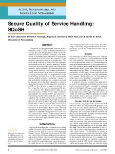
2.6. PERKIN-ELMER 1100 The Perkin-Elmer 1100 crt terminal is an older terminal which features upper and lower case. but has no APL character set.
2.6.1. DOCUMENTATION The Perkin-Elmer 1100 manual is available in the Reference Room. consultant's office in Room 272A
Photograph 2-12:
1158, and in the
Perkin-Elmer 1100
2,6.2. TURNING ON THE TERMINAL The ONiOFF switch is located on the right hand side on the back of the terminal. Press it to the right to turn on the terminal. The terminal will beep and blink if it is working properly. The brightness knob is located just above the ON/OFF switch. Clockwise movement makes the screen darker.
CUCCA
Terminal And Plotter User Manual
November, 1982
Perkin-Elmer 1 100
34
2.6.3. SETTING UP THE TERMINAL
(
Terminal settings can be made with the terminal on or off, and while you are signed on to the computer. Terminal switches are located in a well beneath the logo plate in the upper right-hand corner of the keyboard and a series of configuration keys is on the left-hand side of the terminal.
2.6.3.1. SWITCHES Pry up the logo plate to reveal the switches (do not forget to replace it). The back of the logo plate has all the markings necessary for configuring the terminal. Turn it over after removing it, and place it horizontally to correspond to the switches and use it as a guide. From left to right: 970211 6 204 8 263 2 1 o 0 8 0 0 0 000 1 7 o 0 4 0 0 0 0 0 005 I I
I I
I I
I I
I I
I I
I I
I ,
I I
BAUO RATE
I I
ONE I I
TWO
FULL I I
HALF
s P A
c
I I
E STOP BIT
OUPLEX
M A R K
E V E N
a a a
PARITY
( Figure 2-7:
Perkin-Elmer 1/00 Settings
Usually, all that should be changed on the Perkin-Elmer are the baud rate and duplex.
BAUD RATE
Move switch horizontally, gUided by the settings on the back of the logo plate, until it corresponds to the proper settings.
STOP BIT
Leave at ONE (upperl for all systems.
DUPLEX
HALF (down) for IBM 4341; FULL (up) for DEC-20.
PARITY
MARK for the IBM; SPACE for the DEC-20. If you have to change the setting while the terminal is on, press the Clear All button to record the change.
( CUCCA
Terminal And Plotter User Manual
November, 1982
35
Perkin-Elmer 1100
Photograph 2-13:
Photograph 2-14:
CUCCA
Perkin-Elmer Switches and Logo Plate
Perkin-Elmer Keyboard and Configuration Buttons
Terminal And Plotter User Manual
November, 1982
36
Perkin-Elmer 1100
2.6.3.2. CONFIGURATION BUTTONS
(
There are a series of configuration buttons on the lefthand side of the terminal (see photograph 2- 14). Important settings are noted in italics. They should be set by depressing them.
LINE
Must be depressed to connect to the computer. The same as the REMOTE function on the HP and Concept terminals.
NEW LINE ENABLE
For the DEC-20. should be in an UP (disabled) position. Should be DOWN (enabledl for the IBM.
BREAK
For use with all systems as indicated. Not a configuration key.
SCROLL ENABLE
Should be depressed for all systems.
U/C
When depressed. will produce only upper-case output.
AUTO LF
Inserts an extra line feed for double spacing.
CLEAR ALL
Clears the screen of all text and leaves the cursor in the upper-Iefthand corner and records settings made with the terminal on. Also does a reset on the terminal.
HERE IS
Inoperative on CUCCA systems.
PRINT
Inoperative on CUCCA systems.
(
2.6.4. COMPLETING CONFIGURATION Once you have correctly set all the values. replace the logo plate. Press the CLEAR ALL button to initialize the settings. You are now ready to make a connection to the computer through the Gandalf blue box.
( CUCCA
Terminal And Plotter User Manual
November. 1982
37
Perkin-Elmer 1100
2.6.5. TROUBLE-SHOOTING Problem
CauselRemedy
No Power
If you accidently turn off the terminal in the middle of a session, turn it back on; all the settings will remain. Your program should also be intact. Press carriage return or refresh the screen. No power or a loss of power will also occur if the unit is not plugged in. Check the power cord. If the terminal is plugged in and powered on and there still is no power, the fuse may have blown. Report the condition to Systems Assurance, ext. 3100.
Dark Screen
If you cannot see the cursor on screen, the brightness knob may be turned all th'e way down. Turn it counterclockwise until cursor appears or screen lightens.
Overwriting lines
Depress the SCROLL ENABLE key.
Cursor does not move
Depress the LI N E key.
Upper Case Only
Make sure UIC button on left is in the up position.
Double Spacing
AUTO LF (automatic line feed) button is in the up position.
Everything is correct
Press Clear AI! to initialize the settings.
CUCCA
Terminal And Plotter User Manual
November. 1982
VT101
38
2.7. VT101
(
The VT 10 1, like the Concept-APL8, uses typed-in characters for configuration. It also has a 132 column display capability.
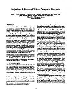
2.7.1. DOCUMENTATION The VT 10 1 User Guide and Reference Card are available in the Reference Room in the S510 area. In addition, the VT 10 1 Set-Up Card, listing all the proper values for the settings, is available at each terminal on the reverse side of the keyboard (see photograph 2-16).
2.7.2. TURNING ON THE TERMINAL The ON/OFF switch is a cylindrical toggle switch located on the left rear side of the terminal. Push it up to turn on the terminal. For adjusting the brightness, see below section 2.7.3.1.
(
Photograph 2-15:
CUCCA
VTf01
Terminal And Plotter User Manual
( November, 1982
VT10,
39
2.7.3. SETTING UP THE TERMINAL -- SET UP MODES A AND B There are two set up modes on the VT101; A and B. You must enter Mode A before Mode B. Enter Set Up Mode A by pressing the Set-Up key in the upper left- hand corner; it is clearly marked. Enter Set-Up Mode B from Mode A by pressing the number 5 key.
2.7.3.1. SET-UP MODE A You change the following settings in this mode: Tabs
The SET/CLEAR tab and CLEAR ALL tabs use the number 2 and 3 keys respectively, as indicated on the main keyboard. To set tabs manually, use the < and > keys on the upper right side of the terminal to set the tabs in the position you want them then press SET/CLEAR. When tabs are set, a "1" will appear above the mode line. Software is available on the DEC-20 to automatically set up the tabs. IBM users may set tabs in Wylbur.
Brightness
Adjust the brightness by pressing the up-arrow and downarrow keys located on the right side of the upper row of the main keyboard. Press as many times as necessary to achieve the desired brightness.
Local/Online
MUST be set to ONLINE for all systems. Press the number 4 key on the main keyboard to switch between the two modes. The corresponding lights above the keyboard will show which mode you are in.
80/132
Choose between using a normal 80 column width or 132, for wider files. To do this, press the number 9 key. You should immediately see the change in character width on your screen. To get back to 80 columns, press 9 again.
2.7.3.2. EXITING SET-UP MODE A When first configuring your terminal, you must enter Set-Up Mode B before exiting SetUp Mode A. If you have already configured your terminal however, and simply want to enter and exit from Set-Up Mode A, press the Set-Up key, as indicated on the terminal screen.
2.7,3,3. SET-UP MODE B To enter Set-Up B mode from Mode A, press the number 5 key on the main keyboard. Seven settings will appear along the bottom of the screen. The four left most settings vary
CUCCA
Terminal And Plotter User Manual
November, 1982
40
VT101
between 0 for off and 1 for on. Using the < and > keys, position the cursor directly over the setting, then use the Toggle 1/0 key (the number 6 key) to vary between 0 and 1. Only the fourth block, third position, Duplex need be changed for the different systems. All others should be left at the following settings: 0101
0010
Figure 2-8:
0000
(
0010 (for lBM) 0000 (for DEC-20)
VTlOl Set-Up Mode B--Four Left Fields
The three right fields are displayed as follows:
p= 7M p= 8N
FIgure 2-9:
Parity (P=)
Baud Rate(T=/R=)
T= 1800 R= 1800 (for IBM) T= 4800 R= 4800 (for DEC-20)
VTlOl Set-Up Mode B--Three RIght Fields
Set to 8N (8 No parity for the DEC-20) by pressing the shift key and then depressing the P key until the proper value appears. Set to 7M (7 Mark) for the IBM in the same manner.
(
Press the number 7 key to alter the transmit speed and the number 8 to modify the receive speed. These must be synchronized. Keep depressing these keys until the desired values appear.
2.7.3.4. EXITING SET-UP MODE B As instructed on the screen, you exit this mode by pressing the Set-Up key again. If you wish to return to Set-Up Mode A, press the number 5 key on the main keyboard. You may reenter Set-Up mode A at anytime by pressing the SETUP key.
2.7.4. RESETTING THE TERMINAL If you want to reset the terminal to its settings when it was first turned on, while in either A or B configuration mode press the RESET key (numeral 0) in the keyboard.
( CUCCA
Terminal And Plotter User Manual
November, 1982
VT10l
41 {O~US
U.S.lUK Auto Repeat
{Q:Off '0""
Auto Wrap {~.=g::
Line Feed!
Q'Da'k Backgrfld
S Creen { l'Ught Backg.-nd Cursor
New Line
{a.OIl I-On
r-r-r.'r...,' 5'" 1 0 I 0 I Margin Bell Key Click AnSIIVT52 Auto XOn XOff
3
{ o·on '0"" { ooon l~On
{~:::;2
{?:8:
4
00
P= 06C-
Set-Up
E=Even Parity O=Odd Parity N=No Parity S=Space Parity M=Mark Parity
Interlace {~:.g::
Q=UnOert:ne { I'Block
momoomo
7=7 Data Bits 8=8 Data Bits
I~UK
Character Set
'b Ii -p£.e?o T=
7 \ll-t;I>",
use A Pen