The requirements of new machines like the linear accelerator TTF (TESLA. Test Facility) at DESY [2] ..... mal convergence rates while relaxation and CG methods considerably slow down the same time the ..... [7] Ch. Van Loan. Computational ...
TESLA Report 2003-31
Multigrid Algorithms for the Fast Calculation of Space-Charge Effects in Accelerator Design Gisela P¨oplau�, Ursula van Rienen, Rostock Bas van der Geer, Eindhoven Marieke de Loos, Soest
Abstract Numerical prediction of the performance of charged particle accelerators is essential for the design and understanding of these machines. Methods to calculate the self-fields of accelerated particles, the so-called spacecharge forces, become increasingly important as the demand for high-quality bunches increases. We report on our development of a new 3D space-charge routine in the General Particle Tracer (GPT) code. It scales linearly with the number of particles in terms of CPU time, allowing detailed design studies with over a million sample particles on a normal PC. The model is based on a nonequidistant multigrid Poisson solver that has been constructed to solve the electrostatic fields in the rest frame of the bunch on meshes with large aspect ratio. Theoretical and numerical investigations of the behaviour of SOR relaxation and PCG method on non-equidistant grids emphasize the advantages of the multigrid algorithm with adaptive coarsening. Numerical investigations have been performed with a selected range of cylindrically shaped bunches (from very long to very short) spanning a wide range of recent applications. The application to the simulation of the photoinjector at the Eindhoven University of Technology demonstrates the power of the new 3D routine.
AMS subject classification: 65N06, 65N55, 65Z05 Key words: trajectories of charged particles, non-equidistant mesh, finite differences, multigrid methods, Poisson solvers.
1 Introduction Nowadays, charged particle accelerators play an important role for scientific research as well as for medical and industrial applications. They typically accelerate small bunches of charged particles in time varying electromagnetic fields. A commonly used figure of merit of the performances scales with the total charge per � This
work was supported by DESY, Hamburg, Germany.
1
bunch divided by the area occupied in position-momentum space. Since particles of equal charge repel each other due to space-charge forces, it is difficult to pack a high charge in a small volume. For this reason, the calculation of space-charge forces is an important part of the simulation of the behaviour of charged particles in these machines. As the quality of the charged particle bunches increases, so do the requirements for the numerical space-charge calculations. Demanding applications such as high-energy linear colliders and self-amplified spontaneous emission free electron lasers (SASE-FELs) require electron bunches of a very specific shape, where any anomaly severely degrades the final performance. The requirements of new machines like the linear accelerator TTF (TESLA Test Facility) at DESY [2] are for example so tight that effects like non-uniform emission from the photo-cathode and non-cylindrically symmetric fields caused by side-coupled cavities have an effect on the output power. Studying these effects requires 3D calculations with a precision matching the quality of the bunch. This full 3D treatment is particularly challenging because the bunches typically have varying shape during their path through the accelerator ranging form very short (’pancake shape’) at instantiation to very long (’cigar shape’) after acceleration. The discretization of Poisson’s equation necessary for the calculation of space charge forces requires for those bunches either equidistant meshes with a huge number of unknowns or non-equidistant meshes which have a high aspect ratio. The aspect ratio of a mesh we define by Amesh � hmax �hmin , where hmax and hmin denote the global maximal and minimal step size, respectively. Most Poisson solvers have serious problems with both discretization types. In this paper we give a new approach of solving Poisson’s equation by a geometric multigrid technique for non-equidistant meshes. The adaptive coarsening described in algorithm 1 is crucial for this method. The goal is that the numerical effort of the resulting algorithm scales linear with the number of mesh nodes on non-equidistant grids as well as on equidistant grids. In section 3 and 4 we work out how this property compares to the behaviour of other Poisson solvers on non-equidistant meshes with large aspect ratio. The numerical investigations of section 4 present tests with cylindrically shaped electron bunches varying according to real life applications from ’cigar’ to ’pancake’ shape. An application of the new 3D space-charge routine is given in section 5 with the simulation of the photoinjector (also called: electron gun) developed at the Eindhoven University of Technology. Although we consider in this paper the special problem of space-charge calculations of charged particle bunches, discretizations with large aspect ratio are always required, where structures with small details are involved. Usually the aspect ratio is restricted to ensure the convergence of the implemented iterative solvers: this affects the creation of Finite Element meshes as well as grids generated by the Finite Integration Technique [15] (see section 2). Here a rule of thumb is to choose Amesh � 10. In our application we allow much higher values for Amesh (see section 4) in order to realize an appropriate resolution of the charged particle bunch with a relatively small number of mesh lines.
2
2
3D Space-Charge Calculation Based on a Multigrid Poisson Solver Adapted for Non-Equidistant Meshes
The space-charge calculations are performed within the tracking procedure, where the trajectories of M macro- or sample particles are computed by means of the relativistic equations of motion given by [10, 12] dγi vi dt dxi dt
� �
q �E i � vi � Bi �� m γi vi vi � � γi v2i �c2 � 1
�
i � 1� � � � � M �
(1)
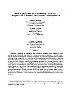
Here, xi and vi are the position and the velocity of the macro-particle i, q and m are the charge and the mass of an elementary particle, where the macro-particles represent the distribution of all particles in a bunch. Further γi :� �1 � v2i �c2 � 1�2 denotes the Lorentz factor and c the speed of light. The electric field Ei and the magnetic flux Bi are the superposition of external and self-induced fields (the socalled space-charge forces) at the position of the i-th macro-particle. The same time the positions of the particles change also the space-charge field changes and has to be recomputed in each time step of the numerical integration of the relativistic equations of motion (1). Space-charge fields of an accelerated bunch have both an electric and a magnetic field component. A useful picture is that the electric part is caused by Coulomb repulsion, where the magnetic part is caused by the fact that moving particles represent a current. A convenient numerical method to calculate these fields is to determine them in a frame traveling with the same velocity as the charged particle bunch (rest frame). In this frame, the magnetic fields are negligible as long as the velocity differences are below the speed of light. The resulting electric field in the rest frame denoted by E¼ is then accurately described by an electrostatic potential ϕ in the form of E¼ � � gradϕ. This electric field can be transformed to yield both the electric and the magnetic fields required in (1) by means of a Lorentz transformation [10]. The focus of this paper is the efficient calculation of these space-charge fields, i. e. the electrostatic potential ϕ in the rest frame of the bunch. Therefore we developed a geometric multigrid method adapted to non-equidistant grids. The determination of the potential requires the solution of Poisson’s equation of the form �∆ϕ � ερ in Ω � Ê3 � (2) 0 ϕ � g on ∂Ω� where ε0 denotes the dielectric constant. The charge density ρ is determined on a non-equidistant grid with mesh lines distributed according to the distribution of the particles in the bunch (see Figure 1). More precisely, this mesh is generated on a box Ω � �ax � bx � � �ay � by � � �az � bz �. The x-coordinate is discretized by Nx 1 subintervals hx�0 , hx�1 , � � � , hx�Nx 1 with bx � ax � ∑Ni�x 0 hx�i . Analogously, the yand z-coordinate are discretized by Ny and Nz subintervals, respectively. Further we introduce hx�i 1 � hx�i � i � 1� � � � � Nx � 1 h˜ x�i � 2 3
(h˜ y�i , i � 1� � � � � Ny and h˜ z�i , i � 1� � � � � Nz in the same way) which is known as mesh spacing on the dual grid. The discretization of Poisson’s equation with second order finite differences on the above described non-equidistant mesh leads to the following system of equations
� � �
h˜ y� j h˜ z�k h˜ x�i h˜ z�k
� �� ��
1 hx�i 1 hy� j 1 hz�k
� � ��
ϕi 1� j�k � 1 1
ϕi� j 1�k
h˜ x�i h˜ y� j � ϕi� j�k 1 � 1 ˜hx�i h˜ y� j h˜ z�k fi� j�k
�
1 hx�i 1 hy� j 1 hz�k
1 1 1
�
� h1 �ϕi� j�k � h1 ϕi�1� j�k � � h1 � ϕi� j�k � h1 ϕi� j�1�k � � h1 ϕi� j�k � h1 ϕi� j�k�1 x�i
x�i
y� j
y�i
z�k
z�k
for i � 1� � � � � Nx � 1, j � 1� � � � � Ny � 1, k � 1� � � � � Nz � 1. The same system of equations is obtained in the field of computational electrodynamics with the application of the Finite Integration Technique (FIT) which has been introduced by Weiland [15]. Making use of the Kronecker product for matrices ’�’ (defined e. g. in [7]) these equations read in matrix vector notation as Aϕ � H˜ z � H˜ y � H˜ x f � with
A � H˜ z � H˜ y � Ax � H˜ z � Ay � H˜ x � Az � H˜ y � H˜ x
(3)
and further H˜ x :�
�diag� �h˜ � h˜ �� � � � h˜ �� �� � � � � � �� � �� � x�1
1 hx�0
Ax :�
x�2
x�Nx 1
1 hx�1
1 hx�1
1 hx�1
1 hx�1
1 hx�2
� h1
x�2
..
�h
. 1
x�Nx 2
�
1 hx�Nx
2
�h
1
� �� �� � � ��
x�Nx 1
The diagonal matrices H˜ y and H˜ z are defined analogously to H˜ x and the finite difference matrices Ay and Az analogously to Ax . Note the different dimensions of the matrices corresponding to the number of mesh lines in every coordinate direcN 1�N 1�N 1 N 1�N 1�N 1 tion. The vectors f � � fi� j�k �i�x 1� j�1y�k�1 z and ϕ � �ϕi� j�k �i�x 1� j�1y�k�1 z contain the values of the right hand side and the potential at the mesh points, respectively.
Figure 1: Mesh line positions ((x� y)–plane) for a Gaussian charge density. The vertical axis shows the total charge in each mesh box.
4
Generally, multigrid algorithms work on a certain number of grids getting coarser and coarser. Operating on equidistant meshes the coarser grids are obtained by removing every second mesh line. This strategy can also be applied for non-equidistant meshes with step sizes which do vary not too much [1]. On grids with large aspect ratio Amesh this scheme would completely fail because the aspect ratio on the coarser grids would not be reduced but maintained or (as in our application) enlarged. Hence the convergence would be slowed down considerably [8]. Detailed descriptions of the multigrid technique can be found for instance in [1, 4]. Here, we explain only our newly developed coarsening strategy. The objective of the coarsening is to obtain a nearly equidistant grid on a certain coarse level. Algorithm 1 Coarsening for Non-Equidistant Meshes Input: Mesh lines of the discretization of Poisson’s equation. While the number of mesh lines on a certain level is greater than a fixed number (� 3) do
�
For δ � 1�4� 1�6� 1�7� 2�0 do: For every coordinate direction: Consider two neighboring step sizes h j and h j�1 . If δh j � hmin or δh j�1 � hmin , the mesh line between this two step sizes is removed and the next step sizes to be considered are hj�2 and h j�3 , else the mesh line between these steps is not removed and the next steps to be considered are h j�1 and h j�2 .
�
The mesh with the smallest Amesh is chosen as the next coarser level.
Output: Sequence of coarser levels with decreasing aspect ratios. Exceptions, where the aspect ratio increases on some level in between are possible.
Remark: Numerical studies have shown that δ chosen as δ � 1�6 or δ � 1�7 provides the best multigrid convergence. Since some discretizations require a more rigorous coarsening strategy to get mesh lines removed the range for δ is considered more widely. The factor δ can differ from one level to the next. � The multigrid scheme applied for the numerical studies has been performed as V-cycle with the following components: two pre-smoothing steps of red-black and two post-smoothing steps of black-red Gauss–Seidel relaxation, further fullweighting restriction and trilinear interpolation as grid transfer operators. This special choice ensures the multigrid scheme to be a positive and symmetric operator which is required for the construction of multigrid preconditioned conjugate gradients (MG-PCG) [6, 5]. The multigrid preconditioner is applied with two Vcycles. The MG-PCG has no advantage compared to MG if the coarsening has an optimal result, that is, if it provides coarser meshes with strictly decreasing aspect ratio. Otherwise MG-PCG has a stabilizing effect [9]. Numerical investigations for space-charge calculations with other multigrid components can be found in [9].
5
3 Comparison with other Poisson Solvers for High Mesh Aspect Ratio In this section we compare our multigrid Poisson solver to widely used relaxation schemes like Gauss–Seidel iteration or the SOR method and (preconditioned) conjugate gradient ((P)CG) algorithms under the special aspect of meshes with high aspect ratio. It is well known for equidistant grids that the multigrid method provides optimal convergence rates while relaxation and CG methods considerably slow down the same time the step size of the discretization decreases [4]. The effect of slow convergence is enforced on meshes with large aspect ratio. The study of the convergence behaviour of the mentioned Poisson solvers requires the knowledge of the eigenvalues of the system matrix A. Since we cannot calculate these eigenvalues for a general mesh spacing we consider a mesh with different mesh sizes in each coordinate direction given by hx �
1 1 1 � hy � � hz � � Nx Ny Nz
(4)
In this setting we regard an anisotropic mesh with hx �
1 1 1 � hy � � hz � α � N N N
(5)
as mesh with large aspect ratio, where α is assumed to be small with α � 1. Thus the aspect ratio yields Amesh � α1 . Although the anisotropic mesh is a special case for a mesh with high aspect ratio if α becomes small, the following investigations demonstrate the main effect of a large aspect ratio on the convergence. The numerical experiments will show that the convergence behaviour is similar on more general non-equidistant meshes. The eigenvalues of the system matrix A can be conveniently derived from the tensor product representation (3) [7]. On the mesh (4) the matrices Ax , Ay and Az achieve the well-known representation of second order finite differences. Taking for example Ax we obtain
�2 ��1 1 � � A � � h � � x
x
which has the eigenvalues λx�i �
�1 2 .. .
�1 ..
. �1
� �
4 π hx i � sin2 hx 2
� �� �� � � �1
..
. 2 �1
2
i � 1� � � � � Nx � 1�
Hence the whole system matrix A has the eigenvalues λi� j�k � 4
h h
y z
hx
2
sin
�π �
�
hx hz 2 π hx i � hy j sin 2 hy 2
�
� ��
� hhy hz sin2 π2 hz i x
�
i � 1� � � � � Nx � 1� j � 1� � � � � Ny � 1� k � 1� � � � � Nz � 1� 6
(6)
taking into account that h˜ x � hx , h˜ y � hy and h˜ z � hz on the grid given by (4). Analogously to the equidistant case we have the following estimation for the eigenvalues λ1�1�1 � λi� j�k � λNx 1�Ny 1�Nz 1 with
λ1�1�1 � 12hx hy hz
and λNx 1�Ny 1�Nz 1 � 4
h2y h2z � h2x h2z � h2x h2y � hx hy hz
(7)
(8)
On the anisotropic mesh (5) these inequalities verify to λ1�1�1 � 12αh3 and
λN 1�N 1�N 1 � 4
2α2 � 1 h� α
(9)
(10)
3.1 Relaxation Methods The effect of meshes with large aspect ratio will be demonstrated here only for the Jacobi relaxation. Results for the Gauss–Seidel iteration or SOR method can be obtained following the explanations in [3]. Denoting by I the identity matrix and by D the diagonal matrix containing the main diagonal of the system matrix A then the iteration matrix of the Jacobi method is given by T J � I � D 1 A� The convergence of the Jacobi relaxation is determined by the eigenvalue µ1�1�1 of the relaxation matrix T J corresponding to the lowest eigenmode. It is given by 1 µ1�1�1 � 1 � λ1�1�1 � d where d�2
h2y h2z � h2x h2z � h2x h2y hx hy hz
the diagonal entries of D. Thus, we get the estimation µ1�1�1 � 1 � using
h2x h2y h2z 3π2 2 h2y h2z � h2x h2z � h2x h2y
(11)
λ1�1�1 � 3π2 hx hy hz �
The convergence of the Jacobi iteration slows down quadratically with decreasing step sizes. For the anisotropic case estimation (11) provides µ1�1�1 � 1 �
3π2 α2 h2 � 2 2α2 � 1
(12)
If α � 1 we obtain the well-known estimation for equidistant grids [3]. The same time α becomes small (as for meshes with large aspect ratio) the eigenvalue µ1�1�1 7
becomes larger, i. e. it tends to one as α tends to zero. Hence the convergence becomes worse. Remark: It is shown in [4] that the smoothing property on anisotropic grids and hence also on non-equidistant grids with large aspect ratio is lost. Since the smoothing property of relaxation algorithms is crucial for the performance of a multigrid scheme one has two possibilities to adapt the multigrid scheme in order to get the optimal convergence rate: One possibility is to adapt the relaxation scheme, the other one is to adapt the coarsening strategy. In our application we have adapted the coarsening scheme. The adaptation of the relaxation scheme has been suggested in [11] with the choice of an alternating zebra line smoother for a non-equidistant mesh based on the Gauss–Lobatto–Legendre points. Yet, in contrast to the discretization shown in figure 1 that mesh has the small step sizes near the boundary and the large step sizes inside the domain Ω. �
3.2 Preconditioned Conjugate Gradient Methods The convergence of CG methods is determined by the condition number of the coefficient matrix A which for the Poisson case is given by condA :�
λmax λmin
� N2
for an equidistant mesh with h � N1 [3], where λmax and λmin denote the maximal and minimal eigenvalue of the matrix A, respectively. Hence, for the Poisson equation the condition number grows quadratically with the number of mesh lines. Making use of (7) and (8) mesh (4) provides the following estimation for the condition number 1 (13) condA � �Nx2 � Ny2 � Nz2 �� 3 Considering further the anisotropic mesh (5) we obtain condA �
1 1 1� 2 3 α
�
N 2�
(14)
Thus the condition number growths the same time the mesh aspect ratio Amesh growths. Preconditioners for CG methods improve the condition number. For our numerical studies we applied the diagonal of the matrix A as preconditioner. Already this simple PCG method provides better convergence results than the SOR method applied on non-equidistant grids (see sections 3.3 and 4). While ILUpreconditioners reach a condition number of condA � O �N �, a multigrid preconditioned CG method provides the optimal condA � O �1� [3]. Nevertheless it has to be emphasized that this optimal condition number can be achieved on non-equidistant meshes with large aspect ratio only with the coarsening scheme of algorithm 1.
3.3 Numerical Test with a Spherical Bunch Electrons with a spherically symmetric Gaussian density distribution served as test case for the theoretical results of (11) and (14). For the numerical test 50,000 electrons have been distributed in a sphere with a radius of 1 mm. The different algorithms have been performed until the relative residual was smaller than 10 2 in the maximum norm. 8
80
MG−PCG PCG SOR
70
CPU time [s]
60 50 40 30 20 10 0 20
25
30 35 40 45 50 number of meshlines for every coordinate
55
60
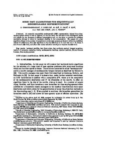
Figure 2: Performance of MG-PCG, SOR and PCG compared on an equidistant mesh for an electron bunch with a spherically symmetric Gaussian density distribution.
80
MG−PCG PCG SOR
70
CPU time [s]
60 50 40 30 20 10 0 20
25
30 35 40 45 50 number of meshlines for every coordinate
55
60
Figure 3: Performance of MG-PCG, SOR and PCG compared on a non-equidistant mesh for an electron bunch with a spherically symmetric Gaussian density distribution. The aspect ratio of the mesh increases from Amesh � 2�3 for N � 20 to Amesh � 5�7 for N � 60, where N is the number of mesh lines in every coordinate direction.
9
The performance of the multigrid preconditioned CG method versus SOR relaxation and PCG with the diagonal of A as preconditioner is shown in figures 2 and 3 for an equidistant and a non-equidistant mesh, respectively. The CPU time has been measured for a number of mesh lines increasing from 20 to 60 for each coordinate which is related to a total number of mesh points increasing from 8,000 to 216,000. Although the aspect ratios of the non-equidistant meshes are not yet very large the convergence of the SOR and PCG method already considerably slow down (see Figure 3). The same time the MG-PCG algorithm keeps the convergence also for the non-equidistant mesh spacing.
4 Investigations for Bunches with Cylindrical Shapes Charged particle bunches ranging from very short to very long play an important role in accelerator design. The aspect ratio Abunch for cylindrically shaped bunches is defined as Abunch � R�γL where R denotes the radius of the cylinder, L the length and γ the Lorentz factor by which the bunch will be stretched in the transformation from the laboratory frame to the rest frame. The particles in the cylinder are assumed to have a uniform distribution. The performance of the 3D space-charge routine was tested within a range of aspect ratios Abunch � 10k with k � �3� �2� � � � � 2� 3 which covers many real life applications. From the numerical point of view, it can be considered a worst-case scenario because the fields near the hard edges have singularities (see [14]) which are typically not present in physical bunches with relative smooth boundaries. 25
CPU time [s]
20
MG−PCG MG PCG SOR
15
10
5
0 20
25 30 35 number of meshlines for every coordinate
40
Figure 4: Performance of MG, MG-PCG, SOR and PCG compared for an electron bunch with Abunch � 1. The aspect ratio of the mesh increases from Amesh � 6 for N � 20 to Amesh � 19 for N � 40. Figures 4, 5 and 6 show the behaviour of the MG and MG-PCG algorithm compared to SOR and PCG applied to different stretched cylindrical bunches. According to the adaptive coarsening strategy there is nearly no difference between the two multigrid algorithms. SOR and PCG slow down considerably the same time the aspect ratio of the bunch and thus the aspect ratio of the mesh increases. All algorithms have been performed until the relative residual was less than 10 2 in
10
25
CPU time [s]
20
MG−PCG MG PCG SOR
15
10
5
0 20
25 30 35 number of meshlines for every coordinate
40
Figure 5: Performance of MG, MG-PCG, SOR and PCG compared for an electron bunch with Abunch � 10 3 (’cigar’ shape). The aspect ratio of the mesh increases from Amesh � 1� 525 for N � 20 to Amesh � 3� 666 for N � 40. the maximum norm. Although the aspect ratio of the mesh for the pancake shaped bunch is much smaller than for the cigar shaped bunch convergence is harder to achieve because the longitudinal electric field of the pancake shaped bunch tends to a constant value as Abunch becomes larger [14].
5 Application: The ’Eindhoven’ DC/RF1 photoinjector After the electrostatic field tests presented in the previous section, we verified the accuracy and applicability of the described space-charge model for a relevant practical application. The simulated device is the ’Eindhoven’ DC/RF photoinjector [13], designed to be used as injector for a future plasma wake field accelerator. Such a plasma-based accelerator can reach much higher electric fields than conventional accelerators, but it sets extreme conditions on the injector. To start with, the electron bunches to be injected into the plasma channel need to be shorter than a fraction of one plasma-wavelength, typical in the order of 100 fs. Furthermore, they need to be focused into the plasma channel being only several tens of micron wide. Finally, to be useful for practical applications, they need to carry a total charge in the order of 100 pC. All constraints combined are very difficult to achieve because space-charge effects will both lengthen the bunch and prevent it from being focused into the plasma channel. A solution is to start with a very long bunch, hereby lowering the charge density and thus all space-charge effects, followed by acceleration and magnetic compression. At the Eindhoven University of Technology a project is started trying to create such bunches without downstream acceleration and without compression in one compact device. In this DC/RF gun, electron bunches are created by photo-emission from a metal cathode and accelerated to 2 MeV in a 1 GV/m semi-DC pulsed electric field, as shown schematically in Figure 7. This extremely high field is used to achieve relativistic velocities as quickly as possible, to reduce space-charge induced emittance growth and bunch 1 DC:
direct current, RF: radio frequency.
11
90 80
MG−PCG MG PCG SOR
CPU time [s]
70 60 50 40 30 20 10 0 20
25 30 35 number of meshlines for every coordinate
40
Figure 6: Performance of MG, MG-PCG, SOR and PCG compared for an electron bunch with Abunch � 103 (’pancake’ shape). The aspect ratio of the mesh increases from Amesh � 22 for N � 20 to Amesh � 686 for N � 40. 2 MV rf 50 fs
Figure 7: 3D schematic of the ’Eindhoven’ DC/RF photoinjector. The DC part, shown not to scale on the left, pre-accelerates a photo-excited 50 fs electron bunch to 2 MeV in a 1 GV/m field. Subsequent RF acceleration to 9.5 MeV is provided by a coaxial coupled 2.6 cell standing wave RF cavity. lengthening at non-relativistic energies as much as possible. The bunches are further accelerated in a state-of-the-art standing wave 2.6 cell RF cavity to 9.5 MeV. A crucial issue in the design of this system is space-charge, as 1 kA peak current is transported from the cathode to relativistic energies without compression. A known limitation of the rest-frame approach of the described space-charge model is its inability to model bunches with large energy spreads. Clearly the simulation method breaks down when a large fraction of the sample particles have relativistic velocities in the average momentum frame. However, if this is not the case, it is far from trivial to predict how the small errors made by the rest-frame assumption propagate into the final simulation results. To verify the accuracy of the rest-frame approach for the Eindhoven DC/RF set-up, we compared the fast 3D mesh-based model with GPT’s relativistically correct 2D point-to-circle scheme [12]. In these 2D calculations all particles are tracked in 3D but represented by uniformly charged circles for the space-charge calculations. To be able to model energy spread properly, velocity differences of 12
9.65
9.60
9.60
9.55
9.55
Energy [MeV]
Energy [MeV]
9.65
9.50 9.45
9.50 9.45
9.40
9.40
9.35
9.35
9.30
-200
GPT
-100
0
100
9.30
200
Position [fs]
GPT
-200
-100
0
100
200
Position [fs]
Figure 8: Comparison between a 100,000 particle simulation calculated with the new space-charge model (right) with a 1000 particle relativistic 2D point-to-point model (left). Both plots are simulated snapshots at the exit of the setup shown in Figure 7. every circle-circle interaction are taken into account resulting in a O �N2 � scaling in CPU time. Without energy spread, the two methods produce identical results as all electromagnetic fields of the DC/RF scheme are cylindrically symmetric and the simulations are started with a cylindrically symmetric initial particle distribution. Figure 8 shows a snapshot of the simulated energy-position projection of 6D position-momentum space for both schemes at the end of the RF cavity. The agreement between the 3D and 2D calculations is near perfect despite the energy spread in the end result. Furthermore, as the CPU time for both simulations is about 2 hours on a standard PC, the new 3D model yields much more detail due to the larger number of particles that can be included. The very good agreement with the 2D method and the high level of detail of the 3D results pave the way to the next step in our simulation efforts, modeling non-cylindrically symmetric initial conditions.
6 Conclusion A new 3D space-charge routine implemented in the tracking code GPT has been investigated in this paper. The new method allowing 3D simulations with a large number of particles on a common PC is based on a multigrid Poisson solver adapted to non-equidistant meshes for the calculation of the electrostatic potential in the rest frame. Numerical results of the 3D routine show that the optimal convergence known for the multigrid method on equidistant grids is maintained on nonequidistant meshes with large aspect ratio. The simulation of the ’Eindhoven’ photoinjector has shown the efficiency and capability of the new 3D space-charge routine.
References [1] W.L. Briggs, Van Emden Henson, and S. McCormick. A Multigrid Tutorial. 2nd edition. SIAM, Philadelphia, 2000. [2] DESY, Hamburg, Germany, tesla.desy.de. DESY-TTF. 13
[3] A. Greenbaum. Iterative Methods for Solving Linear Systems, volume 17 of Frontiers in Applied Mathematics. SIAM, Philadelphia, 1997. [4] W. Hackbusch. Multi-Grid Methods and Applications. Berlin, 1985.
Springer-Verlag,
[5] W. Hackbusch. Iterative Solution of Large Sparse Systems of Equations, volume 94 of Applied Mathematical Sciences. Springer-Verlag, New York, 1994. [6] M. Jung and U. Langer. Applications of multilevel methods to practical problems. Surv. Math. Ind., 1:217–257, 1991. [7] Ch. Van Loan. Computational Frameworks for the Fast Fourier Transform, volume 10 of Frontiers in Applied Mathematics. SIAM, Philadelphia, 1992. [8] G. P¨oplau and U. van Rienen. Multigrid algorithms for the tracking of electron beams. In E. Dick, K. Riemslagh, and J. Vierendeels, editors, Proceedings of the 6th European Multigrid Conference, number 14 in LNSCE, pages 214–220, Berlin, 2000. Springer-Verlag. [9] G. P¨oplau, U. van Rienen, S.B. van der Geer, and M.J. de Loos. Fast calculation of space charge in beam line tracking by multigrid techniques. In Proceedings of the 4th Conference on Scientific Computing in Electrical Engineering (SCEE–2002), Mathematics in Industry. Springer-Verlag, to appear. [10] M. Reiser. Theory and Design of Charged Particle Beams. Wiley, New York, 1994. [11] U. Trottenberg, C. Oosterlee, and A. Sch¨uller. Multigrid. Academic Press, San Diego, 2001. [12] S.B. van der Geer and M.J. de Loos. The General Particle Tracer Code. Design, implementation and application. Phd thesis, TU Eindhoven, 2001. [13] S.B. van der Geer, M.J. de Loos, O.J. Kiewiet, O. J. Luiten, and M.J. van der Wiel. A high-brightness pre-accelerated RF-photo injector. In Proceedings of EPAC 2002 (Paris), pages 1831–1833, 2002. [14] S.B. van der Geer, M.J. de Loos, O.J. Luiten, G. P¨oplau, and U. van Rienen. 3D space-charge model for GPT simulations of high-brightness electron bunches. TESLA-Report 2003-04, DESY, Hamburg (tesla.desy.de/ new_pages/TESLA/TTFnot03.html), 2003. [15] T. Weiland. Eine Methode zur L¨osung der Maxwellschen Gleichungen f¨ur ¨ 31:116–120, 1977. sechskomponentige Felder auf disketer Basis. AEU, Gisela P¨oplau, Ursula van Rienen Universit¨at Rostock Institut f¨ur Allgemeine Elektrotechnik A.-Einstein-Str.2 D-18051 Rostock Germany
Bas van der Geer TU Eindhoven NL-5600 MB Eindhoven The Netherlands
14
Marieke de Loos Pulsar Physics De Bongerd 23 NL-3762 XA Soest The Netherlands
15