Sep 5, 2007 - Data stored in XML is all in text forms, identified by tags, similar to HTML tags. The tags in XML are not predefined as they are in HTML. The.
IJCSNS International Journal of Computer Science and Network Security, VOL.7 No.9, September 2007
45
Test Case Markup Language for Visual Programming Language Mohd Farid Jaafar, Mohd Hasan Selamat and Abdul Azim Abdul Ghani, Faculty of Computer Science and Information Technology, University Putra Malaysia, MALAYSIA Table 1: Overview of some of the VPL
Summary Although Visual Programming Language (VPL) is made easy by using iconic and graphic mode, designing test cases for the program is still a tedious and meticulous work. Recent developments in the field of test case designs have led to a renewed interest in using requirement specification, design specification, complex technique (i.e. Z) and third-party tools; but there are only for non visual programming. One concern regarding to this method is that the information supplied by user in designing test case would be less accurate and thus affected the test suite produced. Therefore, the aim of this paper is to explore the creation of VPL data representation for the test case generation using Extensible Markup Language (XML). Validation and verification of the language created is done by comparing test cases from five VPL programs that are converted into the proposed language with manually-designed test cases. It can be concluded that the test case markup language created in this study is able to create test cases for VPL. This proves that the proposed language able to bridge the gap in test case creation for VPL and thus simplifies the information carried by VPL.
VPL Sketchpad by Sutherland (1963)
• • Pygmalion by Smith (1975) Labview by National Instruments (1986)
• • •
Prograph by Pictorius Inc. (1988)
• • •
Hyperflow Kimura (1991)
•
by
•
Key words: Visual Programming Language, Data Representation, XML, Test Case, Graph.
•
Forms /3 by Burnett et al. (1992)
• •
1. Introduction Visual Programming Language (VPL) is a new programming language that allows the user to specify a program in two or more dimensional ways [1, 2]. It replaces the conventional textual languages with visual expression, icon-based languages, form-based languages and diagram languages. VPL provides graphical or iconic elements, which can be manipulated by the user in an interactive way. The use of graphical GUI builder makes the VPL programming becoming easier. VPLs are becoming more increasingly common in several domains [2]. The VPL targets users with little background in programming. User visualizes the program and uses its icon provided to do programing. Table 1 summarizes a brief overview of some of the VPLs [3].
For Non Visual Programming Language (NVPL), program is developed by writing down the syntax and compiles it. In this program, the syntax is clearly shown. Non-visual programming languages (e.g. C++ and Java) are presented by syntax which can be easily recognized by the user. This is different in VPL. VPL uses a diagram or graphical picture to represent the coding itself. Users only see the graphical representations that have been set. The real code data representation is hidden from users. The data representation of VPL is complex as it carries information, not just for the program but also information regarding the graphical information regarding particular programs. Table 2 shows the comparison for line of code (LOC) between two NVPLs and two VPLs. Table 2: LOC for NPVL and VPL
Language C++ Java FCVPL Mavi
Manuscript received September 5, 2007 Manuscript revised September 20, 2007
Overview A simple constraint based graphics system. Dataflow diagrams. Display and manipulate geometric abstractions. Icon-based programming language. Graphical environment to create test and measurement applications. Measure and analyze real world data and signals. A visual programming language. Object oriented VPL. Supports data flow specification of program execution. Dataflow language for pen computers. Used the concept of Visual Interactive Process. Structured form-based objectoriented language Used spreadsheet.
LOC 6 7 54 15
46
IJCSNS International Journal of Computer Science and Network Security, VOL.7 No.9, September 2007
Based on Table 2, it is safe to say that the codes in C++ and Java examples are comparatively shorter and easier for any user to read. Just imagine for a simple program to produce “Hello World” text, we need to read 54 lines of codes. In fact, some the information in the data representation is not understandable without having depth knowledge of programming. Daboczi [4] has stated that although VPL is based on the visualization, it is more complex than the conventional program. User could misunderstand the graphical representations given by the VPL and creates program that is difference from what being perceived. In gaining confidence, testing should be conducted. There are various methods that can be used in testing VPL and it depends on the type of the VPL itself. In the history of development, testing has been thought as a key factor in determining the quality of software. It is an important process in supporting quality assurance [5, 6] and represents the ultimate review of specification, design and coding [7]. Testing is done by running the program with a certain condition and compares the output whether it meets the expected results. However, designing a test case is a tedious and meticulous task. Although this tedious work is solved with automated tool but few are made for VPL. VPL has a complex data representation compared to the NVP. VPL data representation is in a form of graphical representations and to rely on the requirement would be difficult as it maybe wrongly interpret from user perception and implementation. In fact, some the information in the data representation is not understandable without having depth knowledge of programming. The aim of this paper is to explore the creation of a new VPL data representation for the test case. For this study, XML is used to explore the creation of new data representation. It is believe that the new data representation could contribute in promoting testing and test case design in VPL. The rest of the paper is organized as follows: The next section introduces the related works that related to data representation. Section 3 introduces our new data representation to support test case generation in VPL, while Section 4 talks about the method for the validation and verification of the proposed data representation. Finally, the paper is concluded in Section 5.
XML file, there are also XML schema file. The schema describes the fields, data types, and any constraints, such as required fields. The schema is also defined with XML tags. The format of XML data offers several advantages for programming [8]. XML is a standard language for representing structured information. Many applications for XML have been created for structuring data in various fields includes mathematics; MathML [9], chemical; CML [10], speech; SpeechML [11] and financial report; XFRML [12]. Although XML is used primarily in the context of Internet applications and communications, it can also be used for expressing the specification input to a program generator. The essence of XML is the separation of abstract content from representation. XML can store information in a structured manner. The types of XML elements can be declared to describe the data structure. This allows the programmer to have a sufficient amount of flexibility in describing data. The tags are used to show the beginning and the end of XML elements in a case-sensitive form. In adapting a set of variability to XML, one must decide whether and how to use the attributes for a piece of information. Altogether, these characteristics have made the XML as the first choice data format for data exchange and representation data. By now, there quite a few graph languages for XML. The flavor of formulating graph differs, though, and there are also differences in their expressiveness. There have been number of researches on graph representation using XML, among them are GraphXML [13], GraphML [14], and XGMML [15]. Table 3 show the summarize information about XML graph. Table 3: XML graph researches
Research GraphXML [13]
Field Graph drawing and visualizat ion.
XGMML [15]
Graph descriptio n. Website mapping.
GraphML [14]
Graph structure
2. Related Works The eXtensible Markup Language (XML) is an industrystandard format for representing structured documents, storing and transferring data. Data stored in XML is all in text forms, identified by tags, similar to HTML tags. The tags in XML are not predefined as they are in HTML. The tags can identify the fields by its name. In addition to an
Advantage Interchange format for mathematical representation. Graph based data structure visualization. Exchanging of graphs between different authoring and browsing tools for graphs. Separation in structural and data layer. Can combine with SQL.
Disadvantage Node restriction. Complex when involve complex mathematical equation. Use DTD.
Inefficient. Complex computations are difficult to express.
IJCSNS International Journal of Computer Science and Network Security, VOL.7 No.9, September 2007
Based on the three languages that use XML graph to represent information, a conclusion is made regarding to common tag that should be inside the new language. Table 4 shows common notations of a graph inside the XML. Table 4: Common graph notations in XML
Notation Graph Node Id Edge Source Target
Usage Indicates that the file follows a graph structure. Indicates each statement or node. Unique identification for node. Refers to connection between nodes. The node that points to other node. The node that is pointed by the source node.
The first tag is the tag. This tag is used to explain the data structure in the graph manner. In GraphML and XGMML, the tag has id and edge default attributes. These attributes are used as a graph identification. In TCML, this is ignored because in a file, there is only a graph. The second tag is the tag. The tag explains that there is a node inside the graph. This element can be repeated depending on the number of nodes that exist in a graph. A node has an id attribute that identifies which node does it represents. This is an important attribute where it is used to make sure that the node is connected correctly. The final element inside the tag is the tag. The tag is used to specify the node that is connected. This is done by using the two attributes that it has. The first attribute is the source attribute where it defines the source node. Source node is a node that points to the next node. The second attribute is the target. This is the node that has been pointed by the source node. XML is a structured and well formed document and because of that, each open tag must be complimented by a closed tag. This means that each tag mentioned above has a closing tag. In this investigation there are several limitations in the current data representation to be used for test case generation. Although GraphXML can be used for the description of purely mathematical graphs, it is restricted to the set of nodes and edges but information on graph visualization applications requires more features. The simplicity of GraphXML is great but when it comes to the complex source code, it becomes complicated and not suitable for test case representation. Furthermore, the visual appearance of the graphs, such as the color of the edges and images used in a window containing a specific graph is not relevant for this research, only the value and operation of the node. In GraphML, advanced transformations may result in long-winded style sheets that are intricate to maintain, and most likely to be inefficient. Extension functions appear to be the natural way out of such difficulties. Extensible Stylesheet Language Transfomation (XSLT) should be used primarily to do the
47
structural parts of a transformation, such as creating new elements or attributes, whereas specialized extensions are better for complex computations that are difficult to express or inefficient to run by using pure XSLT. An XGMML is validated against the DTD. XGMML will form documents that can be part of other XML documents. XGMML is based on Graph Modelling Language (GML), but used XML to express the information rather than the text format used by GML.
3. Design of TCML In this research, an empirical study has been chosen as the foundation for the research method. Empirical study is a research where the end result is based on evidence and not just theory. This method is carried out to comply with the scientific method that asserts the objective discovery of knowledge based on verifiable facts of evidence. This research presents a structured data in XML to represent VPL to be used in designing a test case, called Test Case Markup Language (TCML). Figure 1 shows the method in designing the proposed language. Observe VPL Structure Propose New Data Representation Develop Data Representation Validate and Verify Figure 1: Research method
A new data representation is recommended based on the observation of VPL structure. This new data representation will be explained in sub-section 3.1. In addition, this sub-section also described the grammar of the proposed data representation. Later, in sub-section 3.2 and 3.3, the description of the semantic design and the syntax design are explained in details. Lastly, validation and verification is explained in Section 4.
3.1 TCML Architecture Test Case Markup Language (TCML) is an XML-based data representation for VPL. TCML is based from the observation on three languages that use XML graph to represent information. A conclusion is made regarding to common tag that should be inside the proposed data representation. In designing TCML, this research followed the guidelines set by W3C School [16]. The XML’s namespaces are based on the principles by Ogbuji [17] and
48
IJCSNS International Journal of Computer Science and Network Security, VOL.7 No.9, September 2007
Quin [18]. TCML is derived from GraphML, XGMML and GraphXML but with some modifications to suit the testing purpose. The concern when designing TCML is to make sure that it carries the required data in designing test cases. The proposed language must be compatible with VPL and could extract all relevant information. Based from the literatures and case studies that have been done, a proposed XML language is suggested. Table 5 shows proposed notations for TCML. Table 5: Proposed notations for TCML
Notation tcml graph node id type op p1 p2 edge source target
Usage Indicates that the XML file is the TCML file. Indicates that the file follows a graph structure. Indicates each statement or node. Unique identification for node. Used to identify the node type. Explains about the operation done by the node. Represents the value carried by the node. Represents the value carried by the node. Refers to connection between nodes. The node that points to other node. The node that is pointed by the source node.
TCML begins the notation with a tag. This is to define that all the structured data are from TCML. The next tag is the tag. This tag explains that the data is in the form of graph. Just like any other XML graph notations, TCML also has and tag. The has two attributes and three elements. The attributes are key and type. The key will be a unique way to distinct one node with another. The type on the other hand, will determine what kind of node that the graph has. , and are the elements inside the node. defines the type of operation that is done by the node. For example, multiplication, subtraction, value comparison and so on. and represent the value carried by a node. The value can be any, whether a string, a number or a character. The last tag is . Just like any other XML graph notation, is used to pin point the source and to target node. In other word, it will indicate the linkage of the program. Inside exists two attributes; source and target. The source tells the node that points and target tells the node that is being pointed. Listing 1 show EBNF for TCML: tcml b_xml b_tcml e_tcml b_graph e_graph d_node
-> b_xml b_tcml e_tcml -> ‘’ -> ‘’ b_graph e_graph -> ‘’ -> ‘’ (d_node)+ (d_edge)+ -> ‘’ -> b_node c_node e_node
b_node
-> ‘’ c_node -> op_node p1_node p2_node e_node -> ‘’ op_node -> ‘’ op_type ‘’ op_type -> def | connection | io | math | compare def -> ‘DEFINITION’ connection -> ‘START’ | ‘STOP’ | ‘INTERSECTION’ io -> ‘INPUT’ | ‘OUTPUT’ math -> ‘ADD’ | ‘SUBTRACT’ | ‘MULTIPLY’ | ‘DIVIDE’ compare -> ‘IF_EQUAL’ | | ‘IF_GREATER’ | ‘IF_LESS’ p1_node -> ‘’ identifier ‘’ p2_node -> ‘’ identifier ‘’ d_edge -> ‘’ identifier -> letter letter_or_digit* underscore_tail* underscore_tail -> underscore letter_or_digit+ letter_or_digit -> letter | digit letter -> [a-zA-Z] digit -> [0-9] underscore -> _ Listing 1: TCML EBNF
Test Case Markup Language (TCML) is derived from GraphML but with modification to suit the test requirement. The TCML document consists of a graphml element and a variety of sub-elements: graph, node, edge. In the remainder of this section we will discuss these elements in detail and how it is being defined.
3.2 TCML Semantic Semantic is the meaning of a language. It is the important part of the language that dictates how TCML will function. The semantic function of XML is a schema used to explain the meaning and usage of a tag or notation. Schema will determine and constraint all the elements and attributes. Semantic also will make sure that TCML document is structured and valid. The semantic of TCML is divided into four parts: header, graph, node and edge. These four parts are discussed below. The header is a common part to all TCML documents. Every TCML file must have this tag embedded inside. The first line in header defines that it is adheres to the XML 1.0 standard, and encoding of the document is UTF-8. The second line contains the reference to an XML Schema. The schema element is the root element for every XML schema. The schema (schema, element, complexType, sequence, string, Boolean and many more) come from the "http://www.w3.org/2001/XMLSchema" namespace. It also specifies the elements and data types that come from the "http://www.w3.org/2001/XMLSchema" namespace. TCML has an attribute and other element; therefore it is considered as a complex type. In XML, only complex elements can have attributes. The child element of tcml, is
IJCSNS International Journal of Computer Science and Network Security, VOL.7 No.9, September 2007
graph. The header also defines that the defined attribute must appear in the similar order as declared. Graph in TCML is denoted by a graph element. Nested inside a graph element is the declaration of nodes and edges. A node is declared with a node element and an edge is declared with an edge element. The graph element is a complex type because it contains other elements; node and edge. The graph element is also a sequence because it is the declaration of the nodes that must come before the edges. Based on this, the node is specified first and followed by the edge. Edges declaration cannot be written before the nodes. Nodes in the graph are declared by the node element. A node element is a complex type because it contains other elements; key and type. The node element is in sequence manner. The entire elements specified under the node must be in order as defined. This rule has to be followed to ensure that the test case is smoothly generated. In the schema, the number of possible occurrences for an element is defined with the maxOccurs and minOccurs attributes. maxOccurs specifies the maximum number of occurrences for an element and minOccurs specifies the minimum number of occurrences for an element. The default value for both is one. The indicator specifies the maximum number of times for an element to occur. In other word, it means that a node must be declared at least once and there is no limit for the number of nodes to be declared. The node elements have two attributes. The name of the attribute is defined by the XML-Attribute name and must be unique among all the other attributes declared in the document. The purpose of the name is that applications can identify the meaning of the attribute. This statement indicates that the key is the name of the attribute; string is the data type of the attribute required. type is the name of the second attribute which integer is the data type of the attribute required. Required carries the meaning that these two values must be specified, if not, it is considered as an error. The nodes have three elements, op, p1 and p2. These three elements are simple type of elements. The data type for these elements is string. This is not a required element, which means that the element can contain no data. An important aspect to note is the sequence of the elements. The order of the elements must follow the one that is specified by the schema. If somehow the user wrongly specified the sequence, the document becomes invalid. Edges in the graph are declared by the edge element. An edge is a complex type element because it contains two elements: source and target. The indicator
49
specifies the maximum number of times for an edge to occur. An edge must be declared at least once and there is no limit for the number of edges to be declared. The data type of these two attributes is string. This is a required attribute, meaning that the attribute must contain data. Again, it is important to note on the sequence element. The order of the attribute must follow the schema specification. If somehow user wrongly specified the sequence, the document becomes invalid.
3.3 TCML Syntax TCML syntax is inspired from GraphML but with some modifications to suit the test requirement. The TCML document consists of a tcml element and a variety of subelements: header, graph, node and edge. TCML header is common to all TCML documents. It is basically consists of the tcml element. The first line of the document is an XML process instruction, which defines that the document adheres to the XML 1.0 standard and the encoding of the document is UTF-8 which is the standard encoding for the XML documents. TCML is declared as a stand-alone, meaning that it is not attached to other document. The second line contains the root element of a TCML document, tcml. After the tcml element, it is followed by an attribute, which defines the TCML schema. The schema reference is required to validate the document. A graph in TCML is denoted by a graph element. Nested inside a graph element is the declaration of nodes and edges. A node is declared with a node element and an edge is declared with an edge element. Graphs in TCML are basically directed edges. In TCML, there is an order defined for the appearances of node and edge elements. All nodes must be declared first, followed by the edges. This is done to make sure that the data are in order and easy to manipulate. The value of a TCML-Attribute for a graph element is defined by a data element nested inside the element of the graph element. The data element has an XML-Attribute key, which refers to the identifier of the TCML-Attribute. Nodes in the graph are declared by the node element. Each node has an identifier, which must be unique within the entire document. For example, there must not be two nodes with the same identifier in a document. The identifier of a node is defined by the XML-Attribute which is the key. Nodes also contain another identifier name as type. It tells the type of the node. The type is not unique and it can be more than one node with the same type. In TCML there is an order defined for the appearance of the key and type attributes.
IJCSNS International Journal of Computer Science and Network Security, VOL.7 No.9, September 2007
Edges in the graph are declared by the edge element. Each edge must define its two endpoints with the XMLAttributes, source and target. The value of the source and target must be the identifier of a node in the same document. The source represents the node that points to the next node. Target represents the node that is pointed by the source node. Every edge must have a source node and an end node. Edges with only one endpoint (also called loops, self-loop or reflexive edges) are defined by having the same value for source and target. In TCML there is a defined order for the appearance of target and source attributes. It is important to have a source and target for each node because it enables us to see how the program is related. Another important aspect to note here is that to ensure the source and the target is written correctly. The source must be specified before the target is being defined. This is to avoid the node from pointing at the wrong node and reverse direction.
4. Results In order to prove the proposed language can be used to design test cases, a validation and verification in type of case study have been chosen. In validating the language, XML Schema Definition (XSD) was used. With XSD, the structure of document can be used to check constrains of all possible elements, attributes and nesting in TCML. XSD represents a kind of type information for XML values. An XML document conforming to an XSD is said to be valid. In verification, the goal is to assure that the proposed data representation for test case can be used to generate test cases. Five sets of VPL test programs have been conducted to validate the test case produced. The experiment is done in a computer laboratory. For most programs, it is practically impossible to prove that the program is correct on all inputs but by testing the language on various inputs, it will indicate that the language is well functioning.
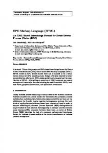
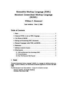
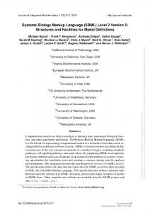
test cases are the same as test cases based on the BVA guideline in designing test cases. The manually design test cases are compared with the generated test cases produced by the TCML. The interpretations are made based upon the numbers or the percentage of the similarities between the data. If the test cases produced by TCML are at par 80% as the manually design test cases, than it is certain that TCML can be used. Graph 1 shows the number of path detected for both manual and tool generated by using TCML. On the question of test case coverage, this study found that TCML covered the entire path on each programs. All paths inside the test program are covered. It can be assumed that TCML is comprehensive in detecting all the statement in a program. 5 4 Numbers
There are three elements under the node element, which explain the details about the node. The elements are op, p1 and p2. The op elements represent the operation of the node. It can be a start node, end node or arithmetic operations that are done by the node. P1 and p2, represent the variables carried by the node. In TCML there is an order defined for the appearance of op, p1 and p2 elements. This is to make sure that the document is structured and well formed.
3
Manual TCML
2 1 0 1
2
3
4
5
Programs
Graph 1: Number of path detected
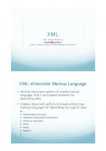
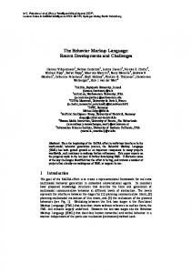
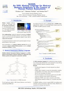
Graph 2 shows the result for each test programs. Looking at the data presented (refer Graph 2), the number of test cases is nearly the same as the number of test cases created manually. Based on Graph 2, the percentage of test cases is derived. The percentage of test cases generated is nearly 89% (refer Table 6) compared to the manually designed test cases. In other words, this result is acceptable to prove that TCML is capable in designing test cases for VPL. It is also interesting to note that in all five test programs conducted, they proved that the TCML can be used as an input to a test case generator and produced a test case. This indicates that the objective of this research has been achieved. The test has successfully proved that TCML can be used to produce test cases, similar to the manual creation of test cases. 14 12 10 Numbers
50
8
Manual
6
TCML
4
A test case generator will create test cases based on TCML. These test cases are then compared with the test cases that are manually design. After collecting all the required data, the next step is to analyze the comparison of relevant test cases. In this research, relevant test case means that the
2 0 1
2
3
4
5
Programs
Graph 2: Number of test cases generated
IJCSNS International Journal of Computer Science and Network Security, VOL.7 No.9, September 2007
Table 6: Percentage of test cases generated by TCML
Programs 1 2 3 4 5 Average
Test Case (%) 80% 100% 100% 83% 83% 89%
5. Conclusions Visual Programming Language (VPL) is a new programming language that allows the user to specify a program in two or more dimensional ways [19, 20]. It replaces the conventional textual languages with visual expression, icon-based languages, form-based languages and diagram languages. VPL provides graphical or iconic elements, which can be manipulated by the user in an interactive way. Although this is a good trend, there is an increasing concern that some of the program develop using VPL is not so accurate. To date there have been few researches conducted on proving the language and there are believe to be like that due to the complexity of data representation in VPL. Furthermore designing a good test case for VPL is as tedious as non-visual programming. This study has been set out to create a data representation that could be easily shared and used to create test cases. This data representation is created using XML. There are several researches that using XML as the input but none of them were found in the area of generating test case design. Most of the researches focus on using XML as visualization representation and as input to solve graph problem. All these information can be used as the basic theory in designing the language but some adjustment and refinement need to be done in making it suitable for test cases environment. In designing test cases for VPL, there are certain factors that must be highlighted. One is the language pattern to represent data inside the XML. This pattern will sketch the XML document, and becomes the basic of the new data representation for VPL test case generator. After all of these considerations had been made, then the test cases generator can be proposed and designed. This paper has shown that TCML can be used to create test cases for a VPL program. The evidence from this research also suggests that TCML can be enhanced to support other programming languages due to the nature of the XML capabilities. The current implementation of TCML is at the prototype stage. More improvements can be done to the language. We suggest that before TCML is introduced, a study similar to this one should be carried out on design for structural programming and object oriented programming, and capabilities to allow new
51
attributes that are relevant rather than the pre-specified attributes. It is recommended that further research can be undertaken in the areas of visualization to enhance the view regarding on how test cases are created.
References [1] Burnett, M. M., Visual Programming, John Wiley & Sons Inc., New York, 1999. [2] Brown, D., Burnett, M., Rothermel, G., Fujita , H. and Negoro, F., Generalizing WYSIWYT Visual Testing to Screen Transition Languages, IEEE Symposium on Human Centric Computing Languages and Environments, Auckland, New Zealand, 2003, pp. 203-210. [3] Shetty, P., Visual Programming Languages – Efficiency of the Visual driving Technology, 2004. [4] Daboczi, T., Kollar, I., Simon, G. and Megyeri, T., How To Test Graphical User Interfaces, IEEE Instrumentation & Measurement Magazine, 2003, pp. 27-33. [5] Harrold, M. J., Testing: A Roadmap Proceedings of the Conference on The Future of Software Engineering ACM Press, Limerick, Ireland 2000, pp. 61-72. [6] Wee, K. L., Siau, C. K. and Yi, S., Automated Generation of Test Programs From Closed Specifications of Classes and Test Cases., 26th International Conference on Software Engineering Scotland, UK, 2004, pp. 96-105. [7] Pressman, R. S., Software Engineering: A Practitioners Approach, McGraw-Hill, New York, 2004. [8] Bradley, J. C. and Millspaugh, A. C., Programming in Visual Basic .Net, McGraw-Hill, New York, 2003. [9] Ausbrooks, R., Buswell, S., Carlisle, D., Dalmas, S., Devitt, S., Diaz, A., Froumentin, M., Hunter, R., Ion, P., Kohlhase, M., Miner, R., Poppelier, N., Smith, B., Soiffer, N., Sutor, R. and Watt, S., Mathematical Markup Language (MathML) Version 2.0, in Carlisle, D., Ion, P., Miner, R. and Poppelier, N., eds., W3C, 2003, pp. Graph for XML. [10] Murray-Rust, P. and Rzepa, H., Chemical Markup Language, SourceF, 1995. [11] Burnett, D. C., Walker, M. R. and Hunt, A., Speech Synthesis Markup Language (SSML) Version 1.0, W3C, 2004. [12] Cover, R., Extensible Financial Reporting Markup Language (XFRML), in Cover, R., ed., OASIS, 2003. [13] Herman, I. and Marshall, M. S., GraphXML - An XML Based Graph Interchange Format, Centrum voor Wiskunde en Informatica, 2000. [14] Brandes, U. and Pich, C., GraphML Transformation, Springer-Verlag Berlin Heidelberg (2004), pp. 90-99. [15] Punin, J. and Krishnamoorthy, M., XGMML (eXtensible Graph Markup and Modelling Language), 2001, pp. XGMML. [16] Quin, L., Extensible Markup Language (XML) 1.1, in Bray, T., Paoli, J., Sperberg-McQueen, C. M., Maler, E., Yergeau, F. and Cowan, J., eds., W3C, 2003. [17] Ogbuji, U., Principles of XML design: Use XML namespaces with care, IBM, 2004. [18] Quin, L., Namespaces in XML 1.1, in Bray, T., Hollander, D., Layman, A. and Tobin, R., eds., W3C, 2004. [19] Burnett, M. M., Visual Programming, John Wiley & Sons Inc., New York, 1999.
52
IJCSNS International Journal of Computer Science and Network Security, VOL.7 No.9, September 2007
[20] Brown, D., Burnett, M., Rothermel, G., Fujita, H. and Negoro, F., Generalizing WYSIWYT Visual Testing to Screen Transition Languages, IEEE Symposium on Human Centric Computing Languages and Environments, Auckland, New Zealand, 2003, pp. 203-210.
Mohd Farid Jaafar received the B.S. and M.S. degrees in Computer Science (Software Engineering) from Universiti Putra Malaysia in 2002 and 2007, respectively. During 2002-2007, he stayed in the University to study software engineering, software testing, software architecture and web based development using various platforms. He’s now with Universiti Putra Malaysia as Tutor. He’s also involved in the Univerisity alternative learning management system. Mohd Hasan Selamat received his M.S. degrees in Computer Science from Essex University in 1981 and MPhil in Information System from East Anglia University, United Kingdom in 1989. His research areas include software engineering and information system. He is now a fulltime lecturer and Head Department of Information System in the Faculty of Computer Science and Information Technology, University Putra of Malaysia. He has published a number of papers related to these areas. Abdul Azim Abdul Ghanis received his M.S. degrees in Computer Science from University of Miami, Florida, U.S.A in 1984 and Ph.D. in Computer Science from University of Strathclyde, Scotland, U.K in 1993. His research areas include software engineering, software metric and software quality. He is now a full-time lecturer in Department of Information System and Dean of the Faculty of Computer Science and Information Technology, University Putra of Malaysia. He has published a number of papers related to software quality areas.