Mar 3, 2003 - As the number of software functions implemented in software has been ... Toshiba Corporation. â â . The authors .... and fault severity do not necessarily provide a specific ... and a list of test items for every function have already.
IEICE TRANS. INF. & SYST., VOL.E86–D, NO.3 MARCH 2003
1
PAPER
Test Item Prioritizing Metrics for Selective Software Testing Masayuki HIRAYAMA† , Nonmember, Osamu MIZUNO†† , and Tohru KIKUNO†† , Members
SUMMARY In order to respond to the active market’s needs for software with various new functions, the system testing must be completed within a limited period. Additionally, important faults, which are closely related to essential functions for users or the target system, have to be removed, preferably in system testing. Many techniques have been proposed to date for effective software testing. Among them, selective software testing is one of the most cost effective techniques. However, most of the previous techniques cannot be applied to short-term development and initial development of software with various new functions because much cost is needed for their testing preparation. In this paper, we propose a new method for selective system testing in which priorities assigned to functions play an essential role in the execution of testing. The priorities are determined based on the evaluation results of three metrics for functions: the frequency of use, the complexity of use scenario, and the fault impact to users. Detailed testing instructions are assigned to test items with high priority, and short and ordinal instructions are assigned to those with low priority. The difference in the volume of testing instruction controls the effort of checking test items. As a result of experimental application to actual software testing in a certain company, we have confirmed that the proposed selective system testing can detect both fatal faults related to key functions and critical faults for the system. key words: Software testing, selective testing, prioritization
1.
Introduction
As the number of software functions implemented in software has been increasing, two trends have formed in software development. The first trend is that the size of software has also been increasing and the structure of software has become more complex[9]. The second trend is that the period and resources for software development are usually limited. In particular, pressure to expedite the shipment of software systems has curtailed development. Correspondingly, in order to assure software quality, software testing should be performed effectively. Software testing is generally divided into three phases: unit testing, build testing, and system testing. Among them, system testing checks the functional behavior of the target software system[1], [16], and thus is directly Manuscript received January 21, 2004. Manuscript revised June 21, 2004. Final manuscript received January 1, 2004. † The author is with the Software Engineering Center, Toshiba Corporation. †† The authors are with Graduate School of Information Science and Technology, Osaka University.
related to the users’ satisfaction. The growing complexity of software structure and the users’ desire for high quality have created great demand for more efficient system testing. An approach toward attaining the demand is to select a certain part of test items and to reduce the number of test items to be tested[12]. This approach is very effective in reducing the time for testing. However, if test items are reduced without any consideration to operation by the user, several critical faults in the untested part might remain in the software related to an important function, and thus, the final quality of the software may become worse. Therefore, the determination of criteria in selecting the test items is a critical issue in selective testing[17]. The software development targeted in this study is the initial development of software open to the public. A typical example is the successive development of embedded software for a new series of cellular phones. Such software usually contains various functions and its development period is quite limited. Thus, the system testing plays an important role in assuring quality within a limited time. Although such software includes many functions, users do not always use all of the functions in the software to the same extent. In an extreme case, there may be several functions that are not used at all. On the other hand, some rarely activated functions may have important roles from the viewpoint of the system’s behavior. Considering these facts, software functions can be classified by applying two criteria or viewpoints: the use frequency of the function and functional importance. As a result, it is reasonable to select test items for functions that are important and frequently used. Here, we review the previous techniques on reducing the number of test items. The previous techniques can be summarized into the following two types: 1. Test item selection from the user’s viewpoint 2. Test item reduction in regression testing In type (1), the user’s operation and operational situation is considered. In order to generate and select test items for system performance evaluation, Musa et al. proposed the use of operational profiles[10], [11]. Operational profiling is a technique, which supports the decision on testing conditions based on the assumption of various user’s operational situations. On the other
IEICE TRANS. INF. & SYST., VOL.E86–D, NO.3 MARCH 2003
2
hand, Kallepalli et al. proposed a statistical testing method using the execution logs for Web systems[8]. In their method, by applying the Unified Markov Model, the user’s scenario and operational procedure are statistically analyzed. Both the operational profile and Unified Markov Model refer to behavior logs in the actual execution or specification information such as control flow, and such logs are used to calculate the operations occurrence probability. However, the operation modeling of the target system requires a large effort in actual development. Since the preparation of testing activity requires much time, it is not applicable to time limited development. In type (2), test item reduction technique for regression testing has been studied. Rothermel et al. considered software safety factors and proposed a selection method of test items using the information on differences in several versions of the software or the information on testing coverage in the first version, and confirmed the effectiveness of their method[13], [14]. Related with this research, Harrold et al. proposed a costeffectiveness evaluation method in regression testing using Rothermel’s method[7]. Elbaum et al. also proposed test item reduction in regression testing[3], [4]. They can control regression test items by evaluating statement coverage and functional coverage. Gupta et al. proposed a testing technique by applying the source code slicing to regression testing[6]. Binkley et al. used semantic differences that focus on the source code’s semantic view and tried to select test items[2]. Wong et al. proposed a test item reduction technique based on path coverage evaluation in system execution[18]. Thus, these techniques are mainly based on the idea of a difference in information among the various software versions, or on the idea of testing coverage and faults information. However, these ideas are only available in regression testing, applying them to newly developing software is difficult. Since the aforementioned techniques require much data on testing activity and much effort in preparing the testing, they are not sufficient for system testing on newly developed software with a short development period. Thus, in this paper, we propose a new method for selective system testing, which is easily applicable to such system testing. The purpose of the proposed selective testing method is to achieve a stable detection of important faults that should be removed within a limited period. Here, “the important faults that should be removed” implies the following: 1. Faults that are related to frequently used functions for users or systems, or 2. Faults that may have critical influence on system reliability or system safety. Faults of the first type are closely related to the functions that are frequently used by system users, or the functions that may cause serious disadvantages to users
in case of abnormal behavior. We can evaluate these faults by using the concept of functional priority. On the other hand, regarding the second type of faults, we believe that such faults make the system run out of control. We can evaluate these faults by using the concept of severity. The definitions of functional priority and fault severity do not necessarily provide a specific relation between these two factors. That is, a function with high priority does not necessarily cause a critical fault with high severity. In this paper, we assume that a list of functions and a list of test items for every function have already been constructed. This assumption is validated because the targeted software development usually prepares a list of functions in the design phase, and it is relatively easy to generate test items from the list of functions (however, the amount of test items usually becomes very large). In the proposed method, we prioritize the functions based on metrics by considering the use frequency and the impact of faults, and we append testing instructions, which enable effective testing based on the priority of each test item. In order to confirm the effectiveness of the proposed method, we performed an experimental application to actual software testing, and evaluated the result of the experiment. As a result, our selective testing method achieved reliable detection of such faults relating to functions with high priority. Moreover, regarding critical faults relating to system safety and system reliability, as many such faults as possible were detected. In this paper, the concept and basic idea of the selective testing method are presented together with examples showing the generation of test items using this method. In addition, the effectiveness of testing instructions for test items is also shown. The rest of this paper is organized as follows: In Section 2, we show an outline of the proposed selective testing method. The conventional testing method is briefly described in Section 2, too. In Section 3, the detailed procedure of the proposed method is explained by referring to an example of an actual development project. Section 4 shows an experiment by applying the proposed method to actual software testing. The results of the experiment are also evaluated in Section 4. Finally, Section 5 concludes this paper. 2.
Proposed Method
The proposed selective testing method tries to detect as many faults that have a serious influence on users as possible in a limited period of testing. Since the testing period is quite limited, we have to develop a straightforward method to apply to the actual testing. To do so, we introduce several metrics to determine the priority of functions. On prioritizing, we mainly focus on the user’s viewpoint by considering the properties of the target software. Before discussing our selective
HIRAYAMA et al.: TEST ITEM PRIORITIZING METRICS FOR SELECTIVE SOFTWARE TESTING
3
Test preparation
Requirements
Functions list
2. Operation 2.1 Railway operation 2.1.1 Registration of railway corp. 1. Select "Register railway’s name" in the right click menu.
Step 1: Construct test items according to the functional specification.
Test specification (Test items) Test execution
2. In the railway newly registration dialog, input a railway corp. name. If cancel button is pressed, the railway corp. name is not registered. 2.1.2 Create a new route 1. Select "New route" from the right-click menu.
Step 2: Conduct testing in the order of the test specification.
New route Register railway corp. Background
Register railway corp.
Input newly created railway corp. and press OK
OK OK Cancel Cancel
New route Register railway corp. Background
Select railway corp.
2. In the "new route mode", select a railway name.
JR TOKYU Corp.
Select Railway corp. OK OK Cancel Cancel Newly Newly registration registration Change ChangeName Name
Test results
Fig. 2 Fig. 1
Software specification document
Outline of conventional software testing in the company Table 1
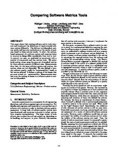
testing method, we summarize the conventional testing method in the next subsection. 2.1 Conventional testing method Figure 1 shows the main procedure of the conventional testing method. As the figure illustrates, in the conventional testing method, test engineers confirm the functional requirements described in a specification document sequentially[12]. In the first step, test items are extracted in sequential order of functional requirements in the specification document. Next, testing is conducted in the order of test items described in the test specification document. Thus, during the conventional testing method, test items themselves are neither evaluated nor selected. Figure 2 and Table 1 show an example of a software specification document and a test specification document, respectively. These are example documents of a Railway Transfer Information System (RTIS), which graphically describes the railway’s transferring information for a certain district. The software specification document in Figure 2 describes the functional specifications for railway registration and station registration, including the attribute inputs for railways and stations. A test engineer constructed the test specification document according to the software specification document. In the test specification document, items for confirmation are listed in the order of functional requirements in the software specification document. 2.2 Outline of the proposed method The proposed selective testing method consists of three phases: functional priority assignment, test instruction assignment, and testing. Figure 3 shows the outline of the proposed method.
Test items by conventional method
Function’s Function’s Testing item Expected result of testing ID name 1 Register name Select "Register railway’s name" in the right click menu, The name "JR1" is registered and of railway then specify the name "JR1" in the dialog and press shown. corp. "OK". 1
Register name Select "Register railway’s name" in the right click menu, No name is registered. of railway then specify a name "JR2" in the dialog and press corp. "cancel".
2
Create a new route
Select "New route " from the right-click menu, then Switch to "New route mode" and close select "JR1" from the railway selection dialog and press the dialog. "OK".
2
Create a new route
2
Create a new route
In "new route mode", left-drag the mouse between start A new route is created and stations are and end points, then release the left button. automatically created on the start and end points. Select "New route " from right-click menu, then select Close the dialog. "JR1" from railway selection dialog and press "Cancel".
2
Create a new route
2
Create a new route
2
Create a new route
In the property dialog for the railway (JR1), change the The name of railway is changed to name of railway to "JR2" and press "OK". "JR2".
2
Create a new route
In the property dialog for the railway (JR2), change the The name of railway is not changed. name of railway to "JR1" and press "Cancel".
2
Create a new route Create a new route Create a new route Extend a route
Select [Edit(E)-Edit curve(L)] from top-menu.
Switch to "Line edit mode".
In "line edit mode", left click on a route.
A black circle appears on the route.
2 2 3
Select "New route " from right-click menu, then pres s "Register new railway" button from railway selection dialog. Select "New route " from right-click menu, then select "JR1" and press "Change railway’s name" button from railway selection dialog.
The new railway registration dialog is shown. Property dialog for the railway(JR1) is shown.
In "line edit mode", left-drag the black circle, and The route becomes a curved-line. release the left button. Right-click on a station, and select "Extend route" from Switch to "Route extend mode". right-click menu.
3
Extend a route In "route extend mode", left-drag the terminal, and release the left-button.
A new terminal station is automatically created at the end point.
4
Delete a route Right-click on a route, and select "Delete " from a pop-up menu, then press [OK] button on the confirmation dialog.
All lines in the route are disappeared.
4
Delete a route Right-click on a route, and select "Delete " from a pop-up menu, then press [Cancel] button on the confirmation dialog. Connect Create two routes, and place a station on the other routes station by moving a station.
No line in the route is disappeared.
5
Connect routes
Create two routes, and place a station on the other station by moving a route.
The stations become transfer stations.
5
Connect routes
Cross two routes, right-click on the intersection point and select "New station...".
The station becomes a transfer station.
6
Change color of a route
Right-click on a route, select "Color..." from a pop-up The color of the route and the stations in menu, and choose a color and press [OK] button on the the route changes. color dialog.
6
Change color of a route
Right-click on a route, select "Color..." from a pop-up The color of the route and the stations in menu, choose a color, and press [Cancel] button on the the route does not change. color dialog.
5
The stations become transfer stations.
First, a specification for testing is constructed by the conventional method mentioned in subsection 2.1. Next, the functions that the target system provides are first prioritized from various viewpoints. In the test instruction assignment phase, detailed testing instructions are appended for the functions with a higher testing priority. On the contrary, for functions with low priority, simple test instructions are appended. The priority of test items inherits the priority of the func-
IEICE TRANS. INF. & SYST., VOL.E86–D, NO.3 MARCH 2003
4
Test preparation
Functions list
Metrics evaluation
Step 1: Prioritize functions Step 1: Construct test items
Test specification (Test items)
Functions list with priority
Step 2: Assign detailed instructions based on the functional priority Test specification with testing instructions
was not used as a metric for test item selection. On the other hand, functions with complicated user operations tend to lead to errors of operation by the user. In addition, these types of software may not be sophisticated and may tend to contain many complex modules. Therefore, in our method, we also evaluate “the complexity of use scenario.” This metric is introduced according to the engineers’ experience in the company. (b) Evaluation
Test execution
Step 2: Do testing Step 3: Conduct testing
Test results Conventional Method
Fig. 3
Test results
Outline of the proposed selective testing method
tion. By changing the detailed level of test specifications, the quality and quantity of software testing can be controlled. Thus, we can effectively utilize the time for the testing and obtain maximum reliability in a limited time. Finally, in the testing phase, testing instructions are executed. In the proposed selective testing, the functions with higher priority are checked with a preference over those with lower priority. 3.
Detailed Procedure
3.1 Step 1: Prioritization of functions (a) Metrics The aim of the proposed selective testing method is the stable detection of faults relating to important functions for users and systems. Thus, in the first step of our method, we extract important functions for users and systems. In order to extract important functions, our method pays attention to the user’s viewpoint and adopts three metrics: “the frequency of use,” “the complexity of use scenario,” and “the fault’s impact to users.” At this point, these metrics are considered to be sufficient for the proposed selective testing method based on the developers’ experience and interviews with them. An important function for users is the function that many users frequently operate with important data, or a function that has a large impact on many people if they encounter a problem[10]. Therefore, we evaluate two metrics, “the frequency of use” and “the fault impact to users” based on the assumption of a problem. The frequency of use was adopted as a test item selection viewpoint in Musa’s Operational profiles[10]. The metric for the fault impact to users was used as a reliability evaluation metric for release version software in Musa’s method although this metric
In priority assignment to a function, the priority for each function is quantitatively evaluated using the metrics mentioned above. We think that easy selection of test items is one of the most important factors in this method. In order to protect ease of selection, the proposed method does not require other documents for testing that are newly developed, nor does the method require other works for system behavior evaluation. By using the existing document and evaluating current functions subjectively, we can easily prioritize the functions to be tested. However, if we adopt a completely subjective criteria, the result of evaluation may become vague. Therefore, we have prepared the evaluation guidelines for each metric as summarized in Table 2. (The notation of this table is based on the reference[5].) With this evaluation guideline, the result of the evaluation can be justified to a certain degree. For example, the use frequency is evaluated as follows: If a function is used 1 time per a month, then the metric is evaluated as 1. Similarly, if a function is used 1 time per a day or 1 time per an hour, then the metric is evaluated as 5 or 8, respectively. Each metric has a value from 1 to 10. The priority for each function is calculated from the values of these three metrics. The priority of test items inherits the priority of the function. In order to evaluate the testing priority as simply as possible, we have integrated these 3 metrics into 1 priority metric. To do so, we used the Analytical Hierarchy Process(AHP)[15], a methodology used in decision making for selecting the best among a set of alternatives, to select the strategy for metrics integration. The overview of the strategy selection is as follows: 1. Prepare 3 metrics M1 (Complexity of use scenario), M2 (Fault impact to users), and M3 (Use frequency). 2. Prepare the following 3 strategies of priority calculation using metrics M1 , M2 , and M3 , which are applicable in the actual software testing. S1 Non-weighted metrics summation S2 Weighted summation with respect to the customer’s loss S3 Weighted summation with respect to the internal software quality
HIRAYAMA et al.: TEST ITEM PRIORITIZING METRICS FOR SELECTIVE SOFTWARE TESTING
5 Table 2
Evaluation guideline for each metric
Fault impact to users (Time for recovery) 1 min./fault 1 hour/fault 1 2 3 4 5 6 Use frequency 1 time/month 1 2
1 time/week 3 4
Complexity of use scenario 1 operation/function 1 2 3 4
1 day/fault 7 8
9
1 week/fault 10
1 time/day 5 6 7
1 time/hour 8 9
1 time/min. 10
10 opers./func. 5 6 7
8
20 opers./func. 10
Table 3
Result of AHP evaluation Strategy S1 S2 S3 M1 0.2 0.2 0.6 Metrics M2 0.2 0.6 0.2 M3 0.2 0.7 0.1 Score 0.2 0.5 0.3
3. Do pairwise comparisons on importance between all metrics pairs (M1 , M2 ), (M2 , M3 ), and (M3 , M1 ). Relative weights for M1 , M2 , and M3 are calculated. In this study, we asked for 3 developers in our company to perform AHP† . According to the result of 3 developers’ discussion, the weights for M1 , M2 , and M3 are determined as 1/3, 1/3, and 1/3, respectively. This means that these 3 developers considered 3 metrics, M1 , M2 , and M3 , have the same importance for system testing. 4. For the metric M1 , do pairwise comparisons with strategies S1 , S2 , and S3 , asking in which strategy M1 is considered important. Consequently, contributions of strategies for the metric M1 is calculated. Similarly, contributions of metrics M2 and M3 to 3 strategies are calculated. In this study, the 3 developers also evaluated the contributions of metrics to each strategy. For example, contribution of M1 to strategy S1 is evaluated as 0.2. Table 3 shows the evaluated contributions for all pairs of metric and strategy. 5. By multiplying the weights and contributions, the scores of supporting strategies S1 , S2 , and S3 are calculated. For example, in the case of S2 , the score is calculated by 0.2 × 1/3 + 0.6 × 1/3 + 0.7 × 1/3 = 0.5. Similarly, the scores for S1 and S3 are calculated as 0.2 and 0.3, respectively. Consequently, since the score of strategy S2 is the highest, strategy S2 is selected for prioritization of test items. As a result, the prioritization was performed according to the strategy S2 . In S2 , the weights for metrics M1 , M2 , and M3 are 0.2, 0.6, and 0.7, respectively. By normalizing so that the sum of all weights becomes 1.0, we obtained the following formula to calculate the † In order to perform AHP, we used a tool, AHPNaviT M , developed by TOSHIBA Corporation.
Table 4
9
Calculated priority for each function in RTIS
Complexity of Fault impact Frequency of manipuration to users (M2) use (M3) (M1) 4 7 3 Register name of railway corp. 10 9 9 Create a new route 1 4 2 Extend a route 2 4 1 Delete a route 2 9 8 Connect routes Change color of a route 10 5 7
Function’s Function’s Name ID (Operation for routes) 1 2 3 4 5 6
Priority 4.7 Medium 9.1 High Low 2.7 Low 2.3 7.6 High 6.6 High
priority of test items: P (M1 , M2 , M3 ) = 0.13 × M1 + 0.40 × M2 + 0.47 × M3 3.2 Step 2: Assignment of detailed instructions In the conventional testing, the granularity of test items depends mainly on the description of the product’s specification document. So, in many cases, the granularity of the test items does not reflect the testing priorities from the user’s viewpoints. In the proposed method, we generate the instructions for testing according to the test priorities for functions, apart from the granularity of each function’s specification. That is, testing instruction is clearly described for the test items with high priority. On the other hand, for the test items with low priority, the instruction directs the testing of only the behaviors that are explicitly described in the specification document. With these specifications, the quality and quantity of testing is controlled, and dependence on the skill of the testing operator can be avoided. 3.3 Case Study In this subsection, an example of priority assignment for functions from the user’s viewpoint, and instructions for test items are shown by using the case study of the specification of a railway transfer information system (RTIS), which was shown in subsection 2.1. (a) Test priority Table 4 shows the calculated priority for each function of the RTIS. In the priority calculation, we evaluated the frequency of use, the complexity of use scenario, and the fault impact to users.
IEICE TRANS. INF. & SYST., VOL.E86–D, NO.3 MARCH 2003
6
In addition, for this application experiment, functions having a calculated score of 5.0 or higher are regarded as high priority functions. Similarly, those having a score ranging from 2.5 to 5.0 are regarded as medium priority functions, and those having 2.5 or smaller as low priority functions. Since we performed the experiment in actual software development, we had to choose the most practical selection of test items. That is, we had to increase the number of test items to be tested to prevent missing critical faults. That’s why we expanded the range of high priority functions to twice as large as those of medium and low priority functions. For example, the function ID. 5 is a function that registers a condition for railway route connection at each station. Concerning this function, the complexity of use scenario is 2, the impact of a fault is 9, and the frequency of use is 8. The priority score of this function is calculated as 7.6. From this score, this function is regarded as a high priority function. (b) Testing instruction First, the expected behavior and the results of target functions are described in the test specifications, and the required operation for the behavior and results are also described by the conventional method. Table 1 shown in Section 2 is an example of test specifications that are generated from the behavior of the RTIS. Next, based on the assigned priority, testing instructions are appended to test items for high priority functions in the selective testing method. These instructions are appended so that engineers can notice the priority of each test item. Of course, by specifying detailed instructions by the experienced engineers, the efficiency of testing will be improved. For example, engineers are instructed to check illegal behaviors of the software, to check for unexpected input characters for a dialog, and so on. For low priority functions, on the other hand, only simple instructions are assigned. Table 5 shows a portion of a test specification document used for the RTIS. In this document, taking into account the test priorities for each function, detailed instruction for high priority test items are added in the test specification document. For example, test items with ID. 2 have a high priority, and therefore testing instructions are given to them. On the other hand, the test items with ID. 4, which is for a function with low priority, are given only a simple instruction, “Check only basic behaviors.” 4.
Application to Software Testing
In this section, we will show the actual application to another software system that is under construction.
GUI part Parse part
Functions definition
Source file parser Conditions
Project window (List of functions to be tested)
Types Invocation of functions
User defined type window
Code to initialize user defined types
Value setting window
Generation pattern window
Criteria analysis
Switching stub & real function
Generation pattern file
Setting test data
Random generation
Auto generator of test items
Test execution dialog
Information flow
Stub & driver generator
Stub & Driver Generation part
Stub & driver
Test items window (List of test items and expected results)
Test results
Test items
Data flow Operation flow
Fig. 4
An overview of the target software tool
4.1 Characteristics of target software We applied the proposed selective testing method to the unit testing support tool(UTST), which is an actual application software developed in a certain company. The UTST is a software tool that has functions to select testing targets, functions to support automatic test data generation, and functions to support stub driver generation. The overall architecture of the UTST is shown in Figure 4. The UTST consists of the Parse part, the GUI part, and the Stub & Driver Generation part. In the GUI part, five windows are implemented. The main window of this tool is the “Project window,” and it has a list of functions to be tested. By using the “Generation pattern window” and the “Value setting window,” the criteria and patterns for generating test items are changed, and automatically generated test items are shown in the “Test items window”. The main specifications of this software are as follows: Language: C language. Size of software: About 30000 LOC. Degree of reuse: All newly developed. 4.2 Purpose An example of test specification generation, taking into account functional priority using the selective testing method, was shown in subsection 3.3. In this subsection, an experiment is shown, in which the generated test specification document is actually used. For the experiment, two independent testing teams, Team-A and Team-B, were organized in order to verify the effectiveness of the proposed method. Team-A used a test specification document prepared by the conventional method, and Team-B used a document prepared using the selective testing method described in Sections 2 and 3. In this experimental application, the evaluation fo-
HIRAYAMA et al.: TEST ITEM PRIORITIZING METRICS FOR SELECTIVE SOFTWARE TESTING
7 Table 5
Example of generated test items with testing instructions
Testing item Expected result of testing Function’s Function’s Detailed instruction (if any) ID name 1 Register name Select "Register railway’s name" in the right click menu, then The name "JR1" is registered and shown. of railway corp. specify a name "JR1" in the dialog and press "OK" . 1
Register name Select "Register railway’s name" in the right click menu, then of railway corp. specify a name "JR2" in the dialog and press "cancel".
2
Create a new route
2
Create a new route
No name is registered.
Select "New route " from right-c lick menu, then select "JR1" from Switch to "New route mode" and close the railway selection dialog and press "OK". dialog. Check the name of railway is appropriately changed. Check the behavior of the listbox in the dialog. In "new route mode", left-drag the mouse between start and end points, then release the left button.
New route is created and stations are automatically created on the start and end points.
Check the route is displayed during dragging. Check the route is a staraight line. Also check tw o stations are created in the appropriate positions. 2
Create a new route
Select "New route " from right-c lick menu, then select "JR1" from Close the dialog. railway selection dialog and press "Cancel". Check the mode and the name of railway is not changed. Check the behavior of the listbox in the dialog.
2
Create a new route
Select "New route " from right-c lick menu, then press "Register new railway" button from railway selection dialog.
2
Create a new route
2
Create a new route
Check the right click menu is properly displayed. Select "New route " from right-c lick menu, then select "JR1" and Property dialog for the railway(JR1) is shown. press "Change railway’s name" button from railway selection dialog. Check the appropriate railways name is shown. The name of railway is changed to "JR2". In the property dialog for the railway (JR1), change the name of railway to "JR2" and press "OK".
2
Create a new route
Check the change of railway’s name is reflected in other views in the application. In the property dialog for the railway (JR2), change the name of The name of railway is not changed. railway to "JR1" and press "Cancel".
2
Create a new route Create a new route Create a new route
2 2
3
3
4
Check whether the name of railway is appropriate. Check the property dialog is closed. Select [Edit(E)-Edit curve(L)] from top-menu. Switch to "Line edit mode". Check whether the mode is unchanged if the menu is canceled. A black circle appears on the route. In "line edit mode", left click on a route. Check the black circle is on the right position. In "line edit mode", left-drag the black circle, and release the left button.
Check the route is displayed during dragging. Extend a route Right-click on a station, and select "Extend route" from right-click menu.
Check only the basic behaviors. Right-click on a route, and select "Delete " from a pop-up menu, then press [Cancel] button on the confirmation dialog.
Delete a route
5
Check only the basic behaviors. Connect routes Create two routes, and place a station on the other station by moving a station.
5
6
6
The route becomes a curved-line.
Switch to "Route extend mode".
Check only the basic behaviors. Extend a route In "route extend mode", left-drag the terminal, and release the left- A new terminal station is automatically created button. at the end point. Check only the basic behaviors. Delete a route Right-click on a route, and select "Delete " from a pop-up menu, All lines in the route are disappeared. then press [OK] button on the confirmation dialog.
4
5
The new railway registration dialog is shown.
No line in the route is disappeared.
The stations become a transfer station.
Check if the message of confirmation window is correct. Connect routes Create two routes, and place a station on the other station by The stations become a transfer station. moving a route. Check if the route is adequately divided into two routes. Connect routes Cross two routes, right-click on the intersection point and select The station becomes a transfer station. "New station...". Check if the station does not become a transfer station on the point other than the cossing point. Change color Right-click on a route, select "Color..." from a pop-up menu, and The color of the route and the stations in the of a route choose a color and press [OK] button on the color dialog. route changes. Change color of a route
Check whether a confirmation dialog appears. Right-click on a route, select "Color..." from a pop-up menu, choose a color, and press [Cancel] button on the color dialog.
The color of the route and the stations in the route does not change.
Check whether a confirmation dialog appears.
cused on the following three questions: Q1) In determining priority, are there a larger number of faults detected for the functions with a higher priority? Q2) In determining priority, does any difference arise in the detection of critical faults related to reliability and safety? Q3) Are the faults that should be removed before system shipment (faults in functions with higher priority and faults in functions essential to system reliability) definitely detected? 4.3 Application procedure (a) Testing teams We compared the tendency of fault detection by the
two Teams A and B. Testing specifications that TeamB used contained testing instructions for test items related to high priority functions and simple instructions for test items related to low priority functions. The meaning of these testing instructions was explained in advance to the engineers who participated in this experiment. Thus, the engineers understood that the instructions had been prepared so as to reflect the test priorities for each test item. In order to avoid deviation due to the engineers’ skills, engineers having almost the same technical experience and skill were assigned to this experiment. The similarity of technical experience and skill among engineers was mainly evaluated by the number of years each engineer had worked, and the individual degree of technical knowledge. Moreover, it should be noted that another group of engineers designed and implemented the target software other than these two groups. In addition, an engineer
IEICE TRANS. INF. & SYST., VOL.E86–D, NO.3 MARCH 2003
8 Table 6
Experiment coordinator
Requirements
Metrics evaluation
Functions list
Function’s Function’s Name ID (From UTST specification) 9
Step 1: Prioritize functions Step 1: Construct test items according to the functional specification.
Step 2: Assign detailed instructions based on the functional priority
Test specification (Test items)
2 42
Functions list with priority
Team A
1 0 34 23 ... 12
Test specification with testing instructions Step 2: Conduct testing in the order of the test specification.
Test results
Fig. 5
A part of prioritized functions
...
Refresh the project window and update information Open a project Show results at a glance in the test case window Newly create a project Start this application Dialog to set detailed values Show the generating pattern window ...
Complexity of manipuration (M1)
Fault impact Frequency of to users (M2) use (M3)
Priority
9
8
6
7.2
10
8
5
6.9
High
7
6
10
8.0
High
9 3 5
10 10 6
2 5 7
6.1 6.7 6.3
High High High High
Delete a function in the project window ...
High
7
6
5
5.7
...
...
...
...
...
2
3
2
2.4
Low
...
...
...
...
...
Team B
Table 7
Step 3: Conduct testing
Test results
Outline of the experiment
Function’s ID ...
12
A part of test items for Team-B
Function’s name
Testing item
...
...
Delete a function in the project window
Expected result of testing Detailed instruction (if any)
Delete a function in the project window from pop-down menu.
... A node of the function should be deleted.
Check only the basic behaviors. ...
(here, we call the engineer experiment coordinator) who prepared the specifications of the target software coordinated the entire experiment. In this experiment, the experiment coordinator was needed to make the experimental environment for each testing team as same as possible. In order to show the difference between the methods used by Teams A and B, the experiment coordinator prepared test specifications for both teams. Note that the experiment coordinator is not needed in actual application of proposed selective testing since one of the testing staff can act as an experiment coordinator. It is also noted that an engineer who appends instructions is not necessarily experienced since the main objective of an instruction for a test item is to notify the priority of the test item to the testing team according to the detailedness of the instruction. The overview of the experiment is shown in Figure 5. (b) Generating test items During the experiment, Team-A and Team-B performed testing independently. Test items generated for the experiment included 32 items for high priority functions, 50 items for medium priority functions, and 54 items for low priority functions. A part of the prioritized functions are shown in Table 6. As was explained in subsection 3.3, the coordinators appended the testing instructions to the test items for the highly prioritized functions. As a result, we obtained the test items for Team-B as shown in Table 7. The faults detected by each team were summarized and fed back to the engineer who developed the software in order to correct and debug.
...
23
Show the generating pattern window
23
Show the generating pattern window
...
...
(1) Columns such as "Name of variables", "Types", "Guideline to generate concrete values", "Concrete values", "Guideline to generate loops" are shown. Invocate the generating pattern window (2) Names of arguments used in functions from menu. to be tested, global variables, and stub functions are shown in "variable name" columns. (3) ...... Do testing for both "new file" and "open existing file" commands. Concrete values should be set for all types of variables such as arguments, global, and stub. Open an existing pattern file or create it newly.
(1) Pattern generation window is shown. (2) Name of pattern file is shown in the title bar. (3) The stub and real modules can be chosen.
When you open an existing pattern file, check both of a real module file and a stub file. ...
...
...
...
4.4 Evaluations (a) Time for testing As for the time required for the actual testing in this experimental application, no significant difference existed between Team-A (the conventional method) and Team-B (the selective method). However, an additional three hours were required for the coordinating group to prepare detailed testing specifications by taking into account the priority of the functions. Since this additional time was shorter than 10 percent of the total time required for the entire testing, we considered this additional time acceptable. (b) Fault detection The result of Team-B obtained from the experimental application is shown in Table 8(a). Each row shows a test item with its priority. A test item is labeled such as 2-(13). The first number shows function’s ID and the second number shows serial number of test item in the function. Each column shows a fault detected by the proposed selective testing. For example, the first fault is detected by test item 2-(13). We can see that test item 12-(3) detected 4 faults and one of these faults
HIRAYAMA et al.: TEST ITEM PRIORITIZING METRICS FOR SELECTIVE SOFTWARE TESTING
9 Table 8
Result of experiment (Team-B)
(a) Fault detection data for Team-B Faults
Test item
Priority
1
2
... ... ... ... v 2-(13) High v 2-(14) High ... ... ... ... 4-(3) Medium 4-(4) Medium 4-(5) Medium ... ... ... ... 12-(2) High 12-(3) High 12-(4) High ... ... ... ... 14-(2) High v 14-(3) High
...
...
30-(2)
Low
3
4
5
...
12 13 14 15
...
22
... ... ...
...
...
...
...
... ... ... v v v
... ... ... ... .. ...
... ... ...
... ... ...
... ... ... ... ...
...
...
...
...
...
...
...
... ... ... ...
...
...
...
...
v
v
v
v
...
...
...
...
...
... ...
v
...
...
... ... ... ... .. ...
...
... ... ... ...
...
...
...
... ... ...
...
...
...
...
...
...
(b) Aggregated result for Team-B
Test priority
Seriousness of faults Critical
Major
Minor
Total
High
1
5
5
11
Medium
0
0
5
5
Low
1
1
4
6
Total
2
6
14
22
Table 9
Aggregated result of experiment for Team-A
Test priority
Seriousness of faults Critical
Major
Minor
Total
High
0
4
1
5
Medium
0
0
4
4
Low
0
2
7
9
Total
0
6
12
18
was also detected by test item 14-(2). In Table 8(b), the number of faults detected in the experimental application is aggregated in a matrix form expressed in terms of test priority and the seriousness of the faults. In aggregating, we only count one test item per one fault. For example, the 2nd fault was detected by two test items, 2-(14) and 14-(3). Since test item 2-(14) detected the fault, the detection of 14-(3) is not counted in Table 8(b). “Test priority” in the table represents the priority for test items that is determined from the evaluated results of viewpoints and metrics. As explained in subsection 3.3, based on the calculated score, the priority is classified into three levels: high, medium, and low. The priority “High” is assigned for a score of 5 or higher, the priority “Medium” for a score ranging from 2.5 to 5, and the priority “Low” for a score of 2.5 or smaller. The “seriousness of faults” means the seriousness if the fault occurs. The seriousness is also classified into the following three levels[9]: Critical: Faults that seriously deteriorate system reli-
ability or product safety, for instance, a fault which makes the system run out of control or halt altogether. Major: Faults whose impacts are smaller than the above and are limited to a portion of the system’s behavior. Minor: Faults whose impacts are relatively small, which allow many users to continue the operation without any troubleshooting, for instance, a fault such as a simple indicator error. Table 8(b) shows the classification of faults detected in the proposed selective method. The columns show classification by the seriousness of faults. That is, Team-B detected 2 critical, 6 major, and 14 minor faults during their testing. On the other hand, the rows show the priority of test items by which faults are first detected. That is, 11 faults are detected by the test items with a high priority, and 5 and 6 faults are detected by the test items with a medium and low priority, respectively. When test items related to high priority functions were tested, Team-A, using the conventional method, detected no “critical” faults, 4 “major” faults, and 1 “minor” fault (as shown in Table 9). On the other hand, Team-B, using the selective testing method, detected 1 “critical” fault, 5 “major” faults, and 5 “minor” faults. (c) Detected faults related to high priority functions As mentioned in subsection 3.1, the priority of test items inherits the priority of the function. Thus, faults detected by test items with a high priority related to functions with a high priority. As far as the number of detected faults related to high priority functions are concerned, 5 faults in total were detected using the conventional method and including all seriousness levels, as shown in Table 9. On the other hand, 11 faults were detected in total by the selective method. For this experimental application, a function with high priority means that the frequency of its use is very high, faults related to the function cause critical damage if they occur, or the use scenario is complicated and numerous faults may easily be incorporated. Faults for high priority functions for users must be detected and removed, without any exception, even if they are trivial. From this viewpoint, the fact that the selective method detected more faults for high priority functions is significant. For this experimental application, testing instructions were provided to the testing operators for testing high priority functions with care. These instructions were considered effective for detecting faults. (d) Detection of critical faults Regarding the detection of serious faults, the conven-
IEICE TRANS. INF. & SYST., VOL.E86–D, NO.3 MARCH 2003
10 Table 10
Result of comparison considering the seriousness Team-A Team-B Type-R: Must be removed.
Type-P: Preferably be removed.
Type-T: Trivial faults.
4
6
1
6
13
10
tional method detected no “critical” faults as shown in Table 9. On the other hand, the selective method detected 2 “critical” faults, including one fault detected from the testing of a high priority test item as shown in Table 8(b). This result shows the effectiveness of the testing instructions for high priority test items. However, the other fault was detected from the test of a low priority test item. By examining the test specifications related to this fault, we found that this fault originated from a test item which partly overlaps another test item for high priority functions performed just prior to this testing. Thus, this fault cannot necessarily be recognized as a fault that was detected in a low priority test item. Therefore, the selective method’s ability to detect “critical” faults can be considered superior to that of the conventional method. (e) Faults that should be removed Considering the above discussions, we examined how completely the testing methods detect the faults that must be removed before shipment. Here, the faults that must be removed mean: (1) Faults that are related to important functions for users or the target system. (2) Faults that have a critical influence on other systems from the viewpoint of reliability or safety. The faults in the dark gray area in Tables 8(b) and 9 must be removed since they are related to both definitions (1) and (2). Similarly, since faults in the medium gray area are related to either (1) or (2), they should preferably be removed. However, faults in the light gray area have no relation to (1) and (2). Detection of these faults is unnecessary. Thus, faults were classified into the following three categories and summarized in Table 10 as: Type-R: Faults that must be removed. Since they are both critical and important to users, they must be removed immediately. Type-P: Faults that should preferably be removed. Since these faults have possibility to be the system failure, they should also be removed as soon as possible. Type-T: Trivial faults. Even though they are identified as faults, it is considered that they might not cause any serious problems immediately. So, they can be removed in the next regular update.
Table 10 shows that the selective method or TeamB detected 6 Type-R faults (that is, 1 + 5 + 0), whereas the conventional method or Team-A detected 4 (that is, 0 + 4 + 0). Moreover, concerning the Type-P faults, the selective method detected 6 faults, whereas the conventional method detected 1. The number of Type-R and Type-P faults detected by the selective method was 12, whereas 5 faults were detected by the conventional method. The selective method (Team-B) showed a fault detection ability about two times higher than that of the conventional method (Team-A). As a result, the selective testing method is considered to be effective for detecting faults that must be or should preferably be removed before the system shipment. 5.
Conclusion
This paper reported on a selective testing method that enables effective testing. The purpose of the selective testing method is to effectively detect the faults that must be or should preferably be removed. In order to accomplish this purpose, functions to be tested are prioritized from various viewpoints, and the testing operation is controlled by using the testing specifications containing testing instructions reflecting the priority. The overall steps of the selective testing method are outlined, and the effectiveness of the method is experimentally confirmed. In the experimental application, functions to be tested were prioritized from the users’ viewpoint, and the testing instructions were provided in the test specification document. By adopting the selective method, the faults that must be or should preferably be removed were successfully detected. Currently, the proposed method has actually been applied to software development of for Web cellular phones in a certain company. Although we have not obtained quantitative data yet, the developers stated that test activity has greatly facilitated their work. Furthermore, since the proposed method took only a few hours to generate testing instructions, applying this method to practical software testing is quite easy. In future work, we intend to confirm the effectiveness of the proposed method quantitatively. In the future, we also intend to investigate the prioritizing method for functions or test items from other viewpoints, and we will try to confirm the effectiveness of the method by applying it to the software testing of actual developments. References [1] B. Beizer. Black-Box Testing. John Wiley & Sons, New York, 1995. [2] D. Binkley. Semantics guided regression test cost reduction. IEEE Trans. on Software Engineering, 23(8):498–516, Aug. 1997. [3] S. Elbaum, A. G. Malishevsky, and G. Rothermel. Test case prioritization: A family of empirical studies. IEEE Trans.
HIRAYAMA et al.: TEST ITEM PRIORITIZING METRICS FOR SELECTIVE SOFTWARE TESTING
11
on Software Engineering, 28(2):159–182, Feb. 2002. [4] S. Elbaum and G. Rothermel. Incorporating varying test costs and fault severities into test case prioritization. In Proc. of 23rd International Conference on Software Engineering, pages 329–338, 2001. [5] N. E. Fenton and S. L. Pfleeger. Software Metrics : A Rigorous & Practical Approach. PWS Publishing, 1997. [6] R. Gupta, M. J. Harrold, and M. L. Soffa. An approach to regression testing using slicing. In Proc. of International Conference on Software Mentenance, pages 299–308, 1992. [7] M. J. Harrold, D. Rosenblum, G. Rothermel, and E. Weyuker. Empirical studies of a prediction model for regression test selection. IEEE Trans. on Software Engineering, 27(3):248–263, 2001. [8] C. Kallepalli and J. Tian. Measuring and modeling usage and reliability for statistical web testing. IEEE Trans. on Software Engineering, 27(11):1023–1036, Nov. 2001. [9] D. M. Marks. Testing very big systems. McGraw-Hill, 1992. [10] J. D. Musa. Software-reliability-engineering testing. IEEE Software, 29(11):61–68, Nov. 1996. [11] J. D. Musa. Software Reliability Engineering: Faster Development and Testing. McGraw-Hill, 1998. [12] W. Perry. Effective methods for software testing. Wiley Publications, 1995. [13] G. Rothermel and M. J. Harrold. Analyzing regression test selection techniques. IEEE Trans. on Software Engineering, 22(8):529–551, Aug. 1996. [14] G. Rothermel and M. J. Harrold. Empirical studies of a safe regression test selection technique. IEEE Trans. on Software Engineering, 24(6):401–419, June 1998. [15] T. L. Saaty. The Analytic Hirarchy Process. McGraw-Hill, 1980. [16] I. Sommerville. Software Engineering. Addison-Wesley, MA, 4th edition, 1992. [17] J. A. Whittaker. What is software testing? and why it is so hard? IEEE Software, 21(1):70–79, 2000. [18] W. Wong, J. Horgan, S. London, and H. Agrawal. A study of effective regression testing in practice. In Proc. of 8th International Symposium on Software Reliability Engineering, pages 230–238, 1997.
Masayuki Hirayama received B.E. and M.E. degrees from Waseda University in 1984 and 1986, respectively. He also received Ph.D. degree from Osaka University in 2003. He has been working at R&D center, Toshiba corporation since 1986. He is currently a senior research scientist in the Software Engineering Center at Toshiba Corporation. His research interests include the software validation and verification technique.
Osamu Mizuno received M.E. and Ph.D. degrees from Osaka University in 1998 and 2001, respectively. He is currently an Assistant Professor in Graduate School of Information Science and Technology at Osaka University. His research interests include the software process improvement and the risk evaluation and prediction of software development. He is a member of the IEEE.
Tohru Kikuno received M.Sc. and Ph.D. degrees from Osaka University in 1972 and 1975, respectively. He joined Hiroshima University from 1975 to 1987. Since 1990, he has been a Professor of the Department of Information and Computer Sciences at Osaka University. Since 2002, he has been a Professor of Graduate School of Information Science and Technology at Osaka University. He also holds a Director of Osaka University Nakanoshima Center from 2004. His research interests include the analysis and design of faulttolerant systems, the quantitative evaluation of software development processes, and the design of procedures for testing communication protocols. He is a senior member of IEEE, a member of ACM, IEICE (the Institute of Electronics, Information and Communication Engineers), and a fellow of IPSJ (Information Processing Society of Japan). He received the Paper Award from IEICE in 1993. He served as a program co-chair of the 1st International Symposium on Object-Oriented Real-Time Distributed Computing (ISORC ’98) and the 5th International Conference on Real-Time Computing Systems and Applications (RTCSA’98). He also served as a symposium chair of the 21st Symposium on Reliable Distributed Systems(SRDS2002).