of a combined Thin Gap and Fast Drift Tube. Chambers for ... goal of the test was to study the combined TGC-sMDT system as tracking ..... quadruplets were put on both sides of the sMDT, resulting in a lever arm for the track angle of 360 mm.
20 1 1 IEEE Nuclear Science Symposium Conference Record
NP5.S-200
Test of spatial resolution and trigger efficiency of a combined T hin Gap and Fast Drift Tube Chambers for high-luminosity LHC upgrades Y. Benhammoul, B. Bittner2, J. Dubbert2, E. Duchovni3, E. Etzionl, A. Kliei3, H. Kroha2, N. Lupu4, G. Mikenberg3, D. Milstein3, Y. Munwes1, o. Sasaki5, P. Schwegler2, M. Shoa3, v. Smakhtin3
Abstract-The forthcoming luminosity upgrade of LHC to super-LHC (sLHC) will increase the expected background rate in the forward region of the ATLAS Muon Spectrometer by approximately the factor of five. Some of the present Muon
Spectrometer components wiD fail to cope with these high rates and wiD have to be replaced. The results of a test of a device consisting of Thin Gap Chambers (TGC) and a fast small diameter Muon Drift Thbe Chamber (sMDT) using the ISO GeV/c muons at the SPS-HS muon beam at CERN are presented. The goal of the test was to study the combined TGC-sMDT system as tracking and triggering device in the ATLAS muon spectrometer after high-luminosity upgrades of the LHC. The analysis of the recorded data shows a very good correlation between the TGC and sMDT track position and inclination. This technology otTers the combination of trigger and tracking and has good angular
and spatial resolutions. The angular resolution is 0.4 mrad for each system individually. For the spatial resolution, the width of
the track residual between TGC and sMDT is 104 /-tm at zero
degree impact angle.
Index Terms-ATLAS, LHC, drift tubes, TGC, muon cham bers, sMDT
I.
in the forward region, one needs to include a detector that can provide a trigger signal in the pseudorapidity region 1.3 < 1111 < 2.4 with an angular resolution exceeding 1 mrad. We propose to build a new tracking and trigger system for the innermost layer of the Muon Spectrometer which would replace the so-called Small Wheel. This device, named the New Small Wheel (NSW), will lead to a significant improvement of the level-l muon trigger and the precision muon tracking performance at high background counting rates, which cannot be achieved by only an improvement of radiation shielding or additional detector layers. The results of a test of a device consisting of new TGC and sMDT prototype chambers using the ISO GeV/C SPS HS muon beam at CERN are presented. Both systems are described in detail in the following sections. The goal of the test was to study the combined TGC-sMDT system as tracking and triggering device in the A'ILAS muon spectrometer after high-luminosity upgrades of the LHC.
INTRODUCTION
During the second long shut-down, probably in 20 17, the LHC will be upgraded to achieve the luminosity up to 2 3.1034 cm-2s-1• The expected background rates in the inner layer of the forward A'ILAS [ 1] Muon Spectrometer [2] at the sLHC are expected to be higher by approximately a factor of five. The present tracking detectors in the innermost layer of the forward A'ILAS Muon Spectrometer, Monitor Drift Tube (MDT) chambers and Cathode Strip Chambers (CSC) for 1111 > 2.0, will not be able to cope with the expected high rates. Furthermore, the present forward Muon Trigger system requires the inclusion of a measurement of the muon trajecto ries in the innermost layer of the forward Muon Spectrometer. This is presently possible by providing hits in the TGC of the inner layer but their pseudorapidity coverage extends only up to 2.0. To greatly improve the trigger capabilities -
Manuscript received November 14, 2011. This work was supported in part by the Benoziyo Center for High Energy Physics, The Israeli Science Foundation (ISF) and the Minerva Foundation. 1 Raymond and Beverly School of Physics and Astronomy, Tel Aviv University, Tel Aviv, Israel. 2 Max-Planck-Institut fUr Physik, Miinchen, Germany. 3Weizmann Institute of Science, Rehovot, Israel. 4Technion Israel Institute of Technology, Haifa, Israel. 5KEK, High Energy Accelerator Research Organization, Tsukuba, Japan.
978- 1-4673-0 120-6/ 1 11$26.00 ©20 1 1 IEEE
II. TGC
DESIGN AND PERFORMANCE
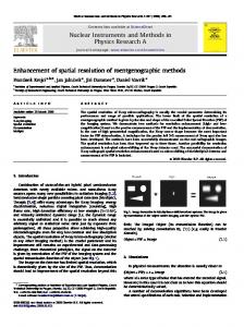
The TGC is a multiwire chamber with 50 J.Lm diameter gold-plated tungsten wires, forming the anode plane. FR4 walls coated with resistive carbon serve as a cathode. The operational gas mixture is 55% of CO2 and 45% of n-pentane. Each gas gap contains: a series of pad readouts for the first level trigger signal, strip readout for high precision accuracy and perpendicular wire readout for a second coordinate mea surement. The schematic view of the TGC is shown in Figure 1 and the parameters of the TGC are shown in Table I. Two TGC quadruplets of 0.6 x 0.4 m2 size each one containing four sensitive gaps were used for the test. The four gaps fit within a total thickness of 50 mm. The position resolution of the TGC using fast digital readout from the strips and Time-over-Threshold method [3], as well as its dependence on the impact angle, were measured with the ISO GeV/c muons from the SPS-HS test beam at CERN. Previous CERN pion test beam results, the muon test beam resolution measurements achieved with a larger prototype and the radiation tests are described in [4] and [5]. Each detector was equipped with 16 strip digital readout channels of a type similar to as those used in the A'ILAS TGC [6]. The external trigger was provided by a coincidence of TGC pads from all the four layers of the quadruplet and two
176 1
7ii' c ex:>
120
.l!l
100
£ c :::J 0 () "0
80
(5
.r:: (/) Q)
60
..c
7 7 7 7
W,:res 7
Z 7 7
� .!. Q) > 0
I I--{>--
40
cD E i=
I I--{>--
20 0 0
2
4
16
6
Position in the layer [strip]
Carlnm coating Fig. 2.
The typical signal from the TGC fitted by Gaussian.
(/)
c
Q) > Q)
Fig. I.
'0 Q;
The schematic view of the TGC.
.0
TGC geometry 1. 4 mm Wire-carbon gap 1. 8 mm Wire-wire space 0 . 1 mm Strip-carbon gap Strip pitch 3. 2 mm 0 . 5 mm Inter-strip gap TGC additional parameters 0 . 4 mm Wire length in layers Number of wires ganged together 5 Strip length 0.6 m 8. 7 x 8. 7 cm2 Pad size 70 kntsquare Carbon plan resistance 470 pF HV blocking capacitance TGC readout parameters Preamplifier gain 0 . 8 V/pC Integration time 16 ns Main amplifier gain 7 7500 electrons at CD Equivalent noise charge
E
PARAMETERS OF THE
-
500 -
cr
400 -
:::J z
(Gaussian fit)
=
65 �m_
300 -
-
200 -
-
100 -
-
0
-1000
-500
J
o
\
1000
500
Residual [�m] Fig. 3.
=
150 pF
TABLE I THE
600 -
TGC.
plastic scintillators. The position resolution is directly related to the profile of the signal from the strips and on the accuracy of the time measurement. The time was measured with a VME 32CH TMC TEG3 KEK module. The track hit position in each layer of the quadruplet was determined by a Gaussian fit. The typical signal from the TGC is shown in Figure 2. Then, a muon trajectory was fitted with a linear function using all the four layers hit positions, and the difference between the measured position and the expected position predicted from fit was defined as the residual, individually for each layer. The particular devices used in the present test show a differential non-linearity not present in the previous much larger prototypes constructed with a different design. Such a differential non-linearity has been corrected using a sinusoidal form. The final deviation was calculated from the fit curve and the residual distribution after such a correction is shown in Figure 3 for one of the TGC
The residual distribution for one of the TGC layers.
layers. The (j value of the Gaussian fit of this distribution was defined as the resolution of the detector. Ideally, not to introduce a bias, one should use only three layers for the linear fit, and look at the residual between the fit predicted position in the fourth layer and the track measured position in the fourth layer. However, in this method the correction of the non-linearity effect becomes nontrivial, so the linear fit using all the four layer hit positions was applied, as described above. The difference between the resolutions of the TGC when using three-out-of-four or all the four layers for the linear fit is no more than 10- 15% as checked in the previous tests. The resolutions of each of the four layers for the different impact angles are shown in Figure 4. A single gap resolution value varies within the 60 I1m- 1 10 11m range. III. sMDT
CHA MBER DESIGN AND PERFORMANCE
The ATLAS muon spectrometer uses the MDT chambers for precision muon tracking. These chambers consist of 6 layers of aluminium drift tubes grouped into two multilayers. Each tube has a diameter of 30 mm and is filled with an Ar:C02 (93:7) gas mixture at 3 bar absolute pressure. The operation with an high voltage of 3080 V results in a maximum drift time of about 700 ns and an average resolution of 80 11m.
1762
E
�
•
c 0
•
(5
"
:s
CfJ OJ a:
&
Layer 1 Layer 2 Layer 3 Layer 4 •
& •
I
& •
"
&
"
•
•
&
I
I
"
•
I
,
• &
"
•
• II
" •
•
" •
Fig. 5. The photograph of the prototype chamber showing the open Faraday cage, the gas system, the HV and readout adapter cards.
o
5
10
15
20
E
Angle [degrees]
E
';;0.25 o
Fig. 4. The resolutions of each of the four TGC layers for the different impact angles.
� CJ) (j)
With a sense wire position accuracy of 20 f..lm, the chamber provides the muon track with an accuracy of 35 f..lm [2]. These detectors were designed for the nominal luminosity of LHC. After the luminosity upgrade by a factor five the occupancy in the drift tube will be too high to allow an efficient muon tracking. To improve the high rate behavior, the use of thinner tubes, while keeping other parameters like gas mixture, gas gain and chamber resolution constant, was proposed [7] [8]. The parameters for the thinner tubes are listed in Table II. These improved concept is called small-diameter Muon Drift Tube (sMDT) chamber. Drift tube parameters 50 Mm diameter W-Re gold plated material 15. 0 mm diameter 400 Mm wall thickness Drift tube operational parameters 2730 V Voltage Gas mixture Ar:C02 (93:7) Pressure 3. 0 bar absolute 2.104 Gas gain Maximum drift time 185 ns Prototype chamber parameters 1152 Number of tubes 384 (only long tubes) Number of tubes in readout 16 Number of layers 90 mm Distance of Multilayers Wire Wire Tube Tube
THE
PARAMETERS OF THE
TABLE II 15 MM DIAMETER DRIFT TUBE CHAMBER.
To test the smaller diameter tubes the prototype chamber was constructed. This sMDT chamber consists of two times 8 layers (multilayers) of aluminium drift tubes of 15 mm outer diameter and 0.4 mm wall thickness. The high voltage of +2730 V applied between the anode wire and the tube wall was chosen to maintain the gas gain at the same value as for the 30 mm diameter ATLAS tubes. The average spatial resolution of individual drift tubes has been measured to be 120.55 ± 0.86 f..lm without time-slewing correction (see Fig. 6). The wire positions of the prototype were measured in a cosmic ray facility [9]. The positioning accuracy is 20 f..lm as
0.3 0.2
-15 mm -30 mm ...... 15 mm --- 30 mm
Diameter Diameter Diameter Diameter
Tubes (Simulation) Tubes (Simulation) Tubes Tubes
0::: 0.15 (j) .0
� 0.1 (j)
OJ .f: 0 05 (f) . O��-L����-L����-L�-L� 4 2 12 14 o 8 10 6
Distance from Wire [mm] Fig. 6. Measured and simulated resolution of the sMDT. The average resolution for the 15 mm diameter tubes is 120 Mm.
for the ATLAS MDT chambers. Combining the single tube resolution and the construction accuracy, the spatial resolution for a track with at least 12 hits is 40 f..lm. The lever arm for the track angle measurement is the multilayer distance plus two time have the multilayer thickness (90 mm+2j 2 ·107 mm= 197 mm). The angular resolution is therefore 0.4 rnrad. A photograph of the completed prototype chamber with visible services is shown in Figure 5. The performance of the sMDT prototype chamber was tested in 20 10 at the SPS test beam facility at CERN. The resolution is shown in Figure 6 and reached the expected level from the experience with the 30 mm drift tubes already used in ATLAS and the Garfield simulations [7]. To measure the resolution, a track was fitted in the sMDT chamber, using all but one layer. The measured radius in this layer was then compared to the expectation from the track fit. These residuals were then corrected with the expected error on the track fit to compute the single tube resolution. The efficiency was also studied as a function of the back ground rate. The prototype chamber was irradiated at the Gamma Irradiation Facility (GIF) at CERN with a 750 GBq 137 Cs source. The efficiency was measured by extrapolating a cosmic muon track reconstructed by a not irradiated part of the chamber in the analysis layer and checking if a hit in the tube was detected within 30' of the single tube resolution. The results are shown in Figure 7. The maximum counting rate achieved in 1 m tubes is 1.2 MHz. The tube length installed in the hottest part of the
1763
� �
cF 1 00 " ::,- - - - - - - - - - - - - - - - - - - - - - - - - - - - - - - - -
>u c Q) ·0
(/) OJ .0
.3
OJ c
.Q E
l!')
o
iE
UJ (/) "0 co (L
60 40 -- 15 mm If, 200 ns dead time
2
4
If,
790 ns dead time
6
8
10
- - Track segment (2·
12
14
16
20
• ..
I �
..
0.6
9.5
2 Background hit rate [kHz/cm j
• o
�
..
Layer Layer Layer Layer
1 2 3 4
191
2.6
2.7
2.8
2.9
3
3. 1
3.2
High voltage [kV]
Fig. 7. Single tube efficiency and calculated track segment reconstruction efficiency for 30 mm and 15 mm diameter tubes for different background flux.
Fig. 9.
The TOC pads efficiency versus operational high voltage.
.l!l
c Q) > Q)
y
'0 Q;
I I I I I I I II
.c
E
I I I I II I I I I I
:::l Z
I o 00 o 0 I
I I I I I I I I I I I
I I II
TGC quadruplet
1
DI P 0 I I I I I I I I II II I I I I I I I I II II I I I I II II TGC quadruplet 2
160
z
Fig. 8.
0.8
0.2
4)
18
•
0.4
- - Track segment (2· 6)
-B-- 30 mm If, 200 ns dead time ___ 30 mm
1.2
The principal scheme of the combined TOC-sMDT test.
Fig. 10 . The time difference between three-out-of-four pad trigger with respect to the beam scintillator.
small wheel will be 0.5 m, corresponding to 17 kHzJcm2 for 1.2 MHz rate per tube. The highest counting rates expected after the LHC upgrade are 14 kHzJcm2 which corresponds to 1.05 MHz per 0.5 m tube. The requirement by the ATLAS collaboration is a track segment reconstruction efficiency of more than 95% up to the highest expected rates. Calculation of this quantity from the measured single tube efficiency shows that the 15 mm diameter tubes can fulfil this requirement even for higher fluxes than the expected 14 kHzJcm2 (see Fig. 7). IV. TGC-sMDT
170
time [ns]
COMBINED TEST
The combined TGC-sMDT test was performed in August 20 1 1 using the 180 GeV/c muons at the SPS-H8 muon beam at CERN. The goal of the test was to study the combined TGC-sMDT system as tracking and triggering device. The principal scheme of the test is shown in Figure 8. The two TGC quadruplets were put on both sides of the sMDT, resulting in a lever arm for the track angle of 360 mm. Signal coincidences from three-out-of-four TGC layer pads were used to provide the trigger for the combined TGC-sMDT device. The efficiency of the TGC pads as a triggering device was checked separately for each layer. While demanding the
presence of the pads signals in the other three layers, the percentage of events in which the fourth layer also had a signal from pads was defined as the efficiency. Pads efficiency versus TGC operational high voltage is depicted in Figure 9 showing that the efficiency for all of the layers is more than 99% above the high voltage value of 2.75 kY. The operational high voltage used in the test was 2.9-3.0 kY. Another important issue is the timing of the trigger signal. The time difference between the three-out-of-four pad trigger with respect to the beam scintillator is shown in Figure 10. 98% of the distribution is within 25 ns which is a beam crossing time planned for the sLHC. Finally, signals from the pads were used as the second coordinate measurement; they were used both by the TGC and sMDT for calibration and alignment corrections. Pads signals from the two TGC quadruplets are very well correlated, as shown in Figure 1 1. To test the TGC-sMDT as a tracking device, the angle of the muon trajectory and the the track position in the middle of the sMDT detector was measured by the TGC and sMDT separately, and the results compared with each other. In order to measure the angle by the TGC, all the eight hits in the two quadruplets were used and the linear fit applied, as
1764
E .s
1::
c o "" 'iii o a.
Q)
E
Q)
:;
(/) C\l Q)
E
. ..
. . . . ... . . .
... .. .
. . . ...
. . .
�
,
E I o ::2: (/)
" ., . . .. . .. . . . .. "
10
20
30
40
50
60
70
1st quadruplet measurement [mm]
TGC hit position [strips]
Fig. 11. Second coordinate position measurement: first TGC quadruplet versus the second one.
Fig. 13.
'0 �
(/)
C
.s 0>
c;,
120
.0
100
E
:::J z
::2:
(/)
140
0> > 0>
'0 Q;
c '" I0
The TGC-sMDT position correlation.
(J
(Gaussian fit) 0.54 mrad
=
80 60
40 20 910
-8
-6
TGC angle [mrad] Fig. 12.
4
-4
6
8
10
TGC-sMDT angle residual [mrad]
The TGC-sMDT angle correlation.
Fig. 14.
described in Section II. The TGC-sMDT angle and position measurement correlations for the 0° impact angle are shown in Figures 12 and 13 respectively. By subtracting the sMDT measured angle and position from the TGC measured ones, the residual distributions were built, as shown in Figures 14 and 15. The a value of the Gaussian fit of the residual distribution and its dependence on the impact angle are shown in in Figures 16 and 17 respectively. As the TGC and sMDT systems demonstrate very similar angular resolutions, the individual resolutions of each of the systems are expected to be less by .J2. Thus, the individual angular resolution is 0.54 mrad/ .J2 0.38 mrad. This is comparable with the expectations of the standalone TGC and sMDT systems. For the spatial resolution, the width of the track residual distribution is 104 {lm at zero degree impact angle (Fig. 15).
The TGC-sMDT angle residual distribution.
.l!l
250
'0 Q;
200
c 0> > 0>
(J
.0
E
:::J z
150
(Gaussian fit) =
104 J.l.m
100 50
=
-fsoo
-1000
1000
1500
TGC-sMDT position residual (JJ.m] Fig. 15.
The TGC-sMDT position residual distribution.
V. CONCLUSIONS
A muon test of the TGC-sMDT combined device was performed showing that such a system offers an attractive solution for triggering and measuring muons at the sLHC. The analysis of the recorded data shows a very good correlation between the TGC and sMDT track position and inclination.
This technology shows good angular and spatial resolutions: the angular resolution of 0.4 mrad is achieved for each system individually. The combined system has a very fast response and is a combination of trigger and tracking, all at a reasonable cost.
1765
[9] O. Kortner Schauerproduktion durch hochenergetische Myonen und
Aujbau eines Hohenstrahlungspriifstandes for hochauflosende ATLAS Muonkammern, PhD Thesis, 2002.
•
•
•
5
•
•
•
15
10
•
•
20
Impact angle [degrees] Fig. 16.
The sigma of the TGC-sMDT angle residual versus impact angle.
• •
•
•
•
• •
•
5
10
15
20
Impact angle [degrees] Fig. 17.
The sigma of the TGC-sMDT position residual versus impact angle.
ACKNOWLEDGMENT
The authors would like to thank the members of the ATLAS TGC group, especially R. Alon, M. Ben Moshe, A. Vdovin and B. Yankovsky, for their support of this work. REFERENCES [1] ATLAS Collaboration, The ATLAS Experiment at the CERN Large Hadron Collider, JINST, s08003. [2] ATLAS Collaboration, ATLAS Muon Spectrometer Technical Design Report, CERNILHCC 97-22 (1997). [3] T. Akesson et aI., Particle identification using the time-over-threshold method in the ATLAS Transition Radiation Tracker, Nuel. Instrum. Meth. A 474, (200 1) 172-187. [4] V. Smakhtin et aI., Thin Gap Chamber upgrade for sLHC: Position resolution in a test beam, Nuel. Instrum. Meth. A 598 (2009) 196. [5] N. Amram et al., Position resolution and efficiency measurements with large scale Thin Gap Chambers for the super-LHC, Nuel. Instrum. Meth. A 628 (2011) 177-181. [6] O. Sasaki and M. Yoshida, ASD IC for the thin gap chambers in the LHC Atlas experiment, IEEE Trans. on Nuel. Science, Vol. 46,(1999) 1871 1975. [7] B. Bittner et aI., Development of muon drift-tube detectors for high luminosity upgrades of the Large Hadron Collider, Nuel. Instrum. Meth. A 617 (20 10) 169 - 172. [8] B. Bittner et aI., Development of fast high-resolution muon drift-tube detectors for high counting rates, Nuel. Instrum. Meth. A 628 (2011) 154 - 157.
1766