IMPROVEMENT CONDITIONAL STATEMENTS WITH MULTIPLE BRANCHES JOURNALTESTABILITY OF INFORMATION SCIENCEFOR AND ENGINEERING 16, 719-731 (2000)
719
Testability Improvement by Branch Point Control for Conditional Statements With Multiple Branches SYING-JYAN WANG AND CHIA-CHUN LIEN Institute of Computer Science National Chung-Hsing University Taichung, Taiwan 402, R.O.C. E-mail:
[email protected]
High-level test synthesis (HLTS) methodologies have attracted much many research interest in recent years as digital design has moved to higher levels of abstraction. Conditional statements in behavioral descriptions tend to produce testability problems and have to be taken care of in the early stage of the design cycle. In this paper, we present an HLTS methodology for the Built-In Self-Test (BIST) environment. Our methods modify conditional case statements in the original design so as to control the number of test patterns applied to modules being tested. As a result, the number of required test patterns can be greatly reduced. This method is especially useful when there is a wide variance in the number of random test patterns required for functional units. Experimental results show that our methods achieve a high degree of fault coverage with a much smaller number of test patterns while the area and time overheads are negligible. Keywords: VLSI, high-level test synthesis, behavioral statement, BIST, conditional branch
1. INTRODUCTION The fast increase in VLSI density has created a great challenge for the design and testing of VLSI circuits. Given the complexity of current VLSI circuits, it is very difficult to control or observe signals inside a chip, which in turn makes circuit testing difficult. Designfor-testability (DFT) methodologies have thus, been developed to reduce the cost and improve the quality of VLSI testing. The two most well-known and widely used DFT techniques are the scan design and Built-In-Self-Test (BIST) techniques. The complexity of circuits is also pushing digital circuit design toward higher levels of abstraction. CAD tools that accept and optimize designs specified in the Register-Transfer Level (RTL) have been used for years while high-level synthesis, which translates designs specified in the behavioral domain to the structural domain (RTL), is becoming popular. In order to consider testability issues in the early stage of a design cycle, high-level test synthesis has been studied intensively in recent years. High-level synthesis for testability (HLTS) tries to transform a design description into another equivalent one with the same functionality and improved testability [1]. The original design may be specified with either RTL or behavior or description. Many HLTS techniques have been proposed, including techniques at the RT level [2-8] and behavioral level [9-13]. Received July 3, 1999; revised December 23, 1999 & March 28, 2000; accepted May 5, 2000. Communicated by Kuen-Jong Lee.
719
720
SYING-JYAN WANG AND CHIA-CHUN LIEN
Behavioral synthesis for testability can be focused on ATPG [9] or BIST [10-13]. These techniques try to find behavioral statements that may cause testability problems and modify the statements for better testability. Conditional statements are the ones that are most likely to cause testability problems. These statements include conditional loop statements [9], ifthen-else statements [13], and case statements [16]. Conditional case statements are commonly used in behavioral and RTL descriptions to provide multiple branch points. This kind of statement may decrease testability in the BIST environment, as the probability that a branch will be taken may not reflect the testability of corresponding module. In other words, some modules may not be provided with enough test patterns while others may be given too many. In this paper, we present methods to deal with the aforementioned testability problem in the BIST-based environment. Our methods modify the design specified in the RTL level so that the testing time can be greatly reduced while the area and time penalty remains negligible. This paper is organized as follows. The testability problems caused by case statements in the BIST environment are discussed in section 2, and our approach to this problem is presented in section 3. We have synthesized circuits according to the presented methods, and the experimental results are given in section 4. The results show that our methods effectively solve the testability problem with insignificant extra cost. Furthermore, the overhead diminishes as the data path becomes wider. Concluding remarks are given in section 5.
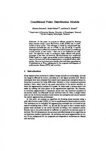
2. TESTABILITY PROBLEMS The Built-In Self-Test (BIST) is a widely used DFT technique [14]. In a circuit with BIST, test patterns are generated on chip, and output responses are also analyzed on chip. In order to achieve this goal, the BIST structure reconfigures part of the functional circuit as a test pattern generator (TPG) and another part as an output response analyzer (ORA). The rest of the circuit consists of the circuit under test (CUT). The TPG is usually made up of a linear feedback shift register (LFSR). The test patterns generated by the TPG are fed to the CUT while the output responses are collected and analyzed by the ORA. The most popular ORA design is the multi-input signature register (MISR), which is also an LFSR. Fig. 1 shows a simple illustration of a general BIST structure.
TPG
n
CUT m ORA Fig. 1. The BIST structure.
TESTABILITY IMPROVEMENT FOR CONDITIONAL STATEMENTS WITH MULTIPLE BRANCHES
721
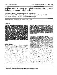
The BIST structure discussed above may encounter some testability problems under some special circumstances. For example, consider the simple ALU structure shown in Fig. 2. The ALU has two inputs coming from registers R1 and R2, and the output is stored in R3. Furthermore, the function executed by the ALU is controlled by the control input R4, which is usually generated by the control circuit. R1
R4
k
R2
ALU
R3 Fig. 2. A simple ALU.
In order to exhaustively test the ALU, registers R1, R2, and R4 should become a test pattern generator which generates an exhaustive number of test patterns for the ALU. With exhaustive testing, all non-redundant stuck-at faults in the circuit under test (ALU in this example) are guaranteed to be detectable. The only problem is that the number of test patterns is usually prohibitive. In order to reduce the number of test vectors needed and thus reduce the test time, either pseudorandom testing or pseudoexhaustive testing is most helpful. With these strategies, the registers can be configured in various ways. For example, during the BIST session, R1 and R2 may become, or the contents in them may come from, a single TPG while register R4 is an independent TGP. When pseudorandom test patterns are applied, fault simulation is usually conducted first to decide the number of test patterns needed to achieve a required level of fault coverage. Now suppose that the number of different functions implemented in the ALU is N. From the point of view of pseudorandom testing, the ideal case is N = 2k, where each function corresponds to exactly one control code. In this case, when we apply L test patterns to the ALU, each functional unit is exercised by about L/2k patterns. However, in real circuits, it is possible that we will have N < 2k. In this case, a functional unit may be exercised by more than one control code, and some control codes may be unused (i.e., they do not activate any functional unit). This will probably lead to some testability problems discussed below. ∑ Suppose that there are unused control codes (stored in register R4 as shown in Fig. 2). In
this case, some test cycles will be wasted during BIST sessions since all the patterns will be generated in R4 but none of the functional units will be activated for the unused codes. ∑ Suppose that functional unit FUi can be activated by mi different control codes, where 2k > mi ≥ 1. Therefore, the number of test patterns accepted by FUi will be around L ¥ mi /2k during a BIST session. The above problems can be illustrated with the example shown in Fig. 3. Fig. 3(a) shows a piece of Verilog code, and Fig. 3(b) shows a block diagram of the circuit synthesized from the code in Fig. 3(a). In order to implement BIST in this circuit, registers B and C become a single PRPG during the testing time, and register A becomes an independent PRPG. Let both registers B and C be m-bit wide; in all there are 22m different input combinations.
722
SYING-JYAN WANG AND CHIA-CHUN LIEN
//Sequential Logic always @(posedge CLK) begin : A = a_input; B = b_input; C = c_input; : end //Combinational Logic always @(
A or B or C
) begin : case(A) 4b0001: OUT=B+C; 4b0010: OUT=B-C; 4b0100: OUT=B