Testing CAN for Distributed System Using the CT Library Hany Ferdinando Department of Electrical Engineering Petra Christian University Siwalankerto 121-131 Surabaya – 60236, Indonesia
[email protected]
Abstract Distributed system consists of seve ral nodes with controllers, which communicate to each other. The communication takes place via fieldbus or wireless network. One can build distributed system using the (Communicating Threads) CT Library, a library developed by Control Engineering group of Twente University, the Netherlands. To use the CT Library for specific fieldbus, one should do some testing. This evaluation is useful to decide whether the chosen fieldbus has good performance inside the CT Library or not. This paper explore the performance of the Control Area Network (CAN) bus in the CT Library for distributed system application. The experiments show that the performance of the CAN bus degrades a little bit if one use this fieldbus in the CT Library, but the portability issue is interesti ng, since one can use the same program in different fieldbus with link driver concept. Keywords distributed system, the CT Library, CAN
1. Introduction Building a distributed system with communication link between the nodes needs a fieldbus to send and to receive data, even to give control command. As an alternative choice, one can use the Communicating Threads (CT) Library to build a distributed system. The CT Library itself is a library based on Communicating Sequential Process (CSP) programming concept in popular programming language. The Control Engineering of Twente University, the Netherlands, develops this library in popular programming language. Inside the CT library, there is separation between hardware independent and hardware dependent part of the software. Therefore, to use the same program on different hardware (e.g. microcontroller or microprocessor), one only changes the driver for specific hardware. The hardware dependent parts are context switch and link driver. Context switch is useful to save the context of current thread and run the next thread in the queue. Link driver relates to hardware specific peripheral. Therefore, there is link driver for each peripheral. Context switch depends on the microprocessor architecture while link driver depends on the microprocessor’s peripheral. One microprocessor has only one context switch but many link drivers (it depends on the number of peripherals) If one wants to build distributed system using the CT Library, he needs to know whether the supported hardware is good enough for this application. One of the supported Sponsor acknowledgment comes here. (This is the only footnote allowed in the paper).
hardware is the fieldbus. This paper explores whether the CAN bus can be used in the distributed application with the CT Library.
2. The CT Library The CSP is a formal algebra that can be used to test multithreading software for undesired condition such as deadlock, livelock and starvation [1]. This algebra was successfully applied in occam programming language for a controller calleed transputer [2]. After the transputer disappeared from the market, several occam-like libraries [3,4] were implemented in popular programming language, in Java, C and C++. With these occam-like libraries, one can use CSP programming concept in PC or microprocessor/microcontroller. The Control Engineering group, University of Twente, developed this library, called the Communicating Threads Library (the CT Library), in three programming languages: Java, C and C++ [1]. Inside this library, there is separation between hardware independent and hardware dependent part of the program. The hardware dependent part used in this paper is the link driver concept [5]. In this concept, each physical link has an associated passive link driver object which encapsulates hardware dependent detail of communication [1]. In the CSP, threads are considered as processes. Processes communicate to each other via channel. This channel uses link driver, therefore, processes do not care what kind of link driver used inside the channel. This link driver can be simple shared memory, peripheral devices (ADC, DAC, etc.) or fieldbuses (CAN, profibus, I2C, etc.). Using the CT Library, one can compose processes as in the CSP algebra. Processes can be composed in parallel, sequential and alternative construct. The CT Library even adds the PriParallel and PriAlternative construct.
3. Problem Formulation If one would like to build distributed system using CAN bus based on the CT Library, he should test whether CAN bus still has good performance inside the CT Library. Therefore, this testing is useful in giving such recommendations of using CAN bus inside the CT Library.
Using the CT Library gives overhead due to the synchronization and other operation inside the kernel. For this reason, every fieldbus must be tested whether the performance is still good or not. The recommendation related to data transfer rate is also useful and this result is expected for the final result. Another important issue is the maximum sampling frequency for the system. For this question relates to the plant, the DC motor is chosen, for this plant needs high sampling frequency.
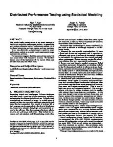
Distributed system consists of several nodes with plants. Each node is connected to certain network to share data. Usually, the microcontroller, PLC or PC is used as node. In the distributed system, nodes work together to achieve certain goal. This idea is implemented here with simple plant. The distributed system used in this experiment is built with two nodes, with microcontrollers on each node. The microcontroller uses ADSP-21992 evaluation board, called ADSP-21992 EZ -KIT LITE. This board has CAN controller on-chip and several useful peripherals such as ADC, DAC, PWM, timer, etc. [6]. ADSP-21992 EZ-KIT LITE comes with VisualDSP++ as the software environment. PC and ADSP-21992 EZ -KIT LITE are connected to each other with USB cable. Via this cable, program is downloaded to the target and the debugging process is done. Both boards are connected to CAN bus via twisted pair cables. The interference signal has no effect on the CAN bus signal since the CAN bus is differential bus. For the plant, the DC motor is chosen. The goal is to control the speed of the motor based on the reference signal with PID controller. As written before, there are two nodes. One node reads reference signal and actual speed of the DC motor and sends the difference to the other node via CAN bus. The later node acts as a controller. It receives data from the first node and calculates PID control action. Finally, this node sends the control action to the motor via PWM unit. Figure 1 [7] shows this configuration. For there is only direction for data communication, this configuration is called one-way configuration. ADSP-21992 EZ-KIT LITE (2)
PWM
CAN bus
Encoder
ADSP-21992 EZ-KIT LITE (1)
Figure 1. One-way configuration
Another configuration is two-way configuration. Here, there are two directions for data communication. The first board sends difference between reference signal and actual speed of the motor and receives control action from the second board. All communications take place in the CAN bus. Figure 2 [8] shows the two-way configuration. Sponsor acknowledgment comes here. (This is the only footnote allowed in the paper).
CAN bus
ADSP-21992 EZ-KIT LITE (1)
Ref. signal
encoder
4. Hardware and Configuration
Ref. signal
Motor driver for this plant uses H-bridge configuration. The first idea was to use this plant for motor speed control system and position control system. Later on, the plant is for motor speed control system only. The H-bridge is connected to Auxiliary Pulse Width Modulation (AuxPWM) of ADSP 21992. ADSP-21992 EZ-KIT LITE (2)
PWM
Figure 2. Two-way configuration
Simple potentiometer circuit serves as a reference signal to the first board. Analog to Digital Converter reads this value then translate it to desired speed of the motor. Encoder is used to read the actual speed of the DC motor. Pulse from the encoder is read via Encoder Interface Unit (EIU). The maximum data rate transfer in the CAN bus in the EZ KIT LITE is 100kbps, by default, because the clock is only 16MHz. If user wants to use higher speed, then the frequency multiplication should be used. This experiment uses only 100kbps.
5. Implementation Software implementation uses the CTC (the CT Library for C). VisualDSP++ provides working environment that is similar to Visual C++. The CT library uses the objectoriented approach. Since C does not support object-oriented programming, Hilderink mimics the behavior of objectoriented programming in C [9] The implementation begins with building the link driver for CAN bus, called CANLinkDriver [10]. For this purpose the CANLinkDriver class is derived from abstract class called LinkDriver. This abstract class provides such a template to write user’s link driver. In CAN bus, one can send and receive data. Therefore, there are two operations: write (to send data) and read (to receive data) in the CANLinkDriver class. These two methods needs synchronization. It means the transmitter waits for acknowledge from the receiver concerning the transmitted data. Before receiving acknowledge signal, the transmitter is blocked. The receiver, blocked by default, waits for data ready to be read. The synchronization uses the semaphore by Dijkstra [11]. Therefore, read() and write() methods are the main method for link driver class. Other methods one must write for link driver are isExternal(), isInputReady() and isOutputReady(), but these methods only return TRUE. Beside the CANLinkDriver, this project needs other link driver for Analog to Digital Converter (ADCLinkDriver),
Pulse Width Modulation (PWMLinkDriver) and Encoder Interface Unit (EIULinkDriver) [7,8]. Their implementation follows the procedure as written above. [7,8] gives more detail information how to write these link drivers. Two active processes are made for both one-way and twoway configurations. Both processes are composed in parallel construct. PID1 uses the ADCLinkDriver to read reference signal from the potentiometer and the EIULinkDriver to read pulse from the encoder. PID1 processes the voltage and the pulse into desired and actual speed of the system, then sends its difference to another board via the CANLinkDriver. Figure 3 shows the PID1 with its channels. ch
PID1
ch
ADCld
ch
CANld
Figure 3. PID1 diagram with three channels
PID2 uses the CANLinkDriver to receive data from PID1 on previous board. PID2 uses this data as an input for PID controller to calculate the control action. The result of this calculation is given to H-bridge circuit via PWMLinkDriver. Figure 4 shows this configuration. ch
PID2
PWMl
CANld
Figure 4. PID2 diagram with two channels
These are the general processes used for both configurations. The difference lies on how both processes transfer data via CAN bus, either in one-way or in two-way. Both processes run in parallel and figure 5 shows this composition in CSP diagram. PID2
||
Table 1 Comparison between writing to channel and one loop CAN message CAN speed (kbps)
EIUld
ch
that the data is read. [10] gives more detailed discussion about this experiment . This experiment is compared to one loop CAN message. One loop CAN message is one node sends data to another node, that node then sends back the data to the sender. This is similar to how producer and consumer send and receive data, except there is no the CT Library involved in this communication. For both experiments, it is assumed that there is no other traffic on the bus. The result of these experiments are shown in table 1. From table 1, there are always differences between 2nd and 3rd column, but they are decrease as the data rate transfer of the CAN bus increases. This experiment used the ADSP -21992 EZ-KIT LITE on 16MHz CCLK. It shows that the data latency is due to the CAN speed not the channel. Indeed, using channel slows down the performance of the system. But for certain application with low sampling frequency, this will not raise problems
PID2
Figure 5, PID1 and PID2 are composed in parallel
6. Experiments Experiment for both configurations uses six data rate transfers of the CAN bus. The chosen maximum data rate transfer is 100 kbps. The first experiment uses the simple producer and consumer processes. Producer sends a value to consumer and consumer sends an acknowledge signal to producer to notify Sponsor acknowledgment comes here. (This is the only footnote allowed in the paper).
8 12.5 25 50 80 100
Writing to channel (ms) 20.4413 13.0220 6.5775 3.3906 2.1974 1.7986
One loop CAN message (ms) 16.4479 10.5267 5.2712 2.6439 1.6551 1.1962
The next experiment is to use the CANLinkDriver in the one-way and two-way configurations. The interest point is the maximum sampling frequency. It depends on the dynamic behavior of the plant. Plant such as DC motor needs high sampling frequency. If it is assumed that the DC motor needs 1 ms for sampling time (1kHz), then the dynamic behavior of the DC motor cannot be used to determine the maximum sampling frequency. Another constraint for the maximum sampling frequency is the latency on the CAN bus and this is the main problem for the latency is not fixed. Therefore, one cannot use table 1 to determine the maximum sampling frequency. The pre-experiments show that the difference between maximum and minimum value of table 1 is around 2000 ticks (it means 0.25 ms in 8 MHz clock). All operations with interrupt is controlled by the interrupt of sampling frequency, except for the encoder operation. The encoder’s interrupt is every 1 ms and its Interrupt Service Routine (ISR) consumes 1.25 µs. To determine the maximum sampling frequency, one needs to add certain value to table 1. That value is taken from the 2000 ticks plus 30% for safety margin. The calculation results are shown in table 2. Table 2. Sampling time and frequency for each CAN speed in one-way configuration. CAN Speed (kbps) 8.00 12.50
Sampling time (ms) 20,9163 13,4970
Sampling frequency (Hz) 47,8097 74,0905
25.00 50.00 80.00 100.00
7,0525 3,8656 2,6724 2,2736
141,7937 258,6904 374,1990 439,8263
Figure 6 shows the plot of table 2. The relationship between data rate transfer and maximum sampling frequency is almost linear. This is interesting, since one can predict the maximum sampling frequency based on the data rate transfer value. For the two-way CAN message, the minimum sampling time at least twice the value shown in table 1. But time consumed by ADC and EIU should be taking into account also. The estimation of sampling frequency will be based on this result with 2000 tick and 30% safety as explained in the one-way configuration for each CAN communication. Table 3 shows the maximum sampling frequency for two-way configuration while figure 7 shows its plot. Sampling Frequency vs CAN speed for one-way configuration 450
439,8263
Sampling frequency (Hz)
400 374,1990 350 300 258,6904
250 200 150
141,7937
100 74,0905 47,8097
50 0 0
20
40
60
80
100
CAN speed (kbps)
Figure 6. Plot of table 2
Table 3. Sampling time and frequency for each CAN speed in two-way configuration CAN Speed (kbps) 8,00
Sampling time (ms) 41,6825
Sampling Freq (Hz) 23,9909
12,50
26,8440
37,2523
25,00
13,9550
71,6589
50,00
7,5813
131,9044
80,00
5,1948
192,5020
100,00
4,3973
227,4149
Sampling frequency vs CAN speed for two-way configuration 250
Sampling frequency (Hz)
227,4149 200
192,5020
150 131,9044 100 71,6589 50 37,2523 23,9909 0 0
20
40
60
80
100
CAN speed (kbps)
Sponsor acknowledgment comes here. (This is the only footnote allowed in the paper).
Figure 7. Plot of table 3
The relationship between data rate transfer and the maximum sampling frequency is almost linear also, as in the one-way configuration.
7. Discussions The differences as shown in table 1 are due to the overhead in the CT Library. The synchronization in the CT Library takes lots of time. But as the data rate transfer increases, this latency is decreased. These experiments uses 100 kbps for the maximum data rate transfer and the ADSP-21992 is driven by 16 MHz clock. In the CAN bus, the parameters to configure the data rate transfer are only candidates. One has to try it in real plant. Capacitance and length of the bus influence it. Therefore, the pre-experiment begins with testing parameters for CAN speed. The result is amazing, since ADSP-21992 EZZ-KIT LITE with 16MHz clock cannot achieve speed above 100 kbps (with the simple twisted cable as the CAN bus) Actually, one can use frequency multiplier to achieve 160MHz clock for the ADSP-21992 EZ -KIT LITE. With 160MHz clock, the 1 Mbps can be achieved hopefully. Unfortunately, the experiment with all parameters for the new clock failed. This is the reason why this paper only discusses data rate transfer up to 100 kbps. The right procedure to determine the maximum sampling frequency is based on the dynamic behavior of the plant. Plant with slow response such as temperature control can use low sampling frequency, but plant with fast response such as motor should use higher sampling frequency. The modeling and simulation procedure can be used to get the dynamic behavior of the plant. For this experiment uses the plant as a complementary part, the sampling time of the motor is assumed as 1 ms (1kHz). Using sampling time higher than the dynamic behavior of the plant makes the res ponse of the system late. However, using lower sampling time is useless. Plant needs some time to response the action given by the controller. With low sampling time, the controller may read signal from plant although the plant still needs time to response. The result is the same as the previous reading and this is useless. Using 1 ms as sampling time is impossible. Values in table 1 shows that one loop CAN message needs more than 1 ms in 100 kbps. The 100 kbps is the highest data rate transfer can be achieved. Therefore, the maximum sampling frequency cannot be determined form the dynamic behavior of the plant. The idea is using the time calculation (see table 1) to determine the maximum sampling frequency. The latency from pre-experiment can be used to calculate this. The problem is the latency is not fixed and some safety margin should be included here. Figure 6 and 7 show the plot of CAN speed vs maximum sampling frequency. These plots show that the relationship between CAN speed and maximum sampling frequency is almost linear. With this result, one can predict the maximum sampling frequency from the data rate transfer.
Those plots also show that there is tendency that the plot can be approximate by exponential curve. To get the complete response from the lowest up to the highest CAN speed is useful to get this approximation curve. This experiment can be continued with CAN speed higher than 100 kbps (up to 1 Mbps). One may use more sophisticated cable for the CAN bus.
8. Conclusions To use the CT Library in distributed system is useful since the separation between hardware dependent and hardware independent part can make the system portable. By making link drivers for other peripherals, one can have a library for link drivers. The CANLinkDriver in the CT Library may be used successfully for the plant with slow response. However, plant with higher response is not suitable, especially for 100 kbps data transfer rate. Therefore, using the CANLinkDriver for this kind of plant needs higher CAN speed. In general, the CAN bus has limited data rate transfer to implement control system in the distributed system. Using the CAN bus only for data communication is a good choice, but for control command, this decision should be considered again. If the new version of the CAN bus has speed higher than 1 Mbps, this experiment can be done.
REFERENCES [1] Orlic, B., Hany Ferdinando, Jan F. Broenink, “CAN Fieldbus Communication in the CSP-Based CT Library”, Proceeding of the 4th PROGRESS Symposium on Embedded System. Nieuwegein, the Netherlands, October 22, 2003. [2] W. A. Burns A., Real -Time Systems and Programming Languages Ada95, Real-Time Java and Real-Time POSIX, 3rd ed., Essex, UK, Pearson Education Ltd., 2001. [3] Welch, P. H., “Java Threads in the Light of occam/CSP,” presented at Architecture, Language and Patterns for Parallel and Distributed Applications, WoTUG-21, Amsterdam, 1998. [4] Hilderink, G. H., J. F. Broenink and A. W. P. Bakers, “Communicating Threads for Java,” presented at Proc 22n d World Occam and Transputer User Group Technical Meeting, Keele, UK, 1999 [5] Hilderink, G. H., A. W. P. Bakers and J. F. Broenink, “A Distributed Real-time Java System Based on CSP”, Proc 3rd IEEE Int Symp. on Object Oriented Real-Time Distributed Computing ISORC 2000, Newport Beach, CA, USA, 2000. [6] Analog Device Inc., ADSP-21992 EZ-KIT LITE Evaluation System Manual, Analog Device, Inc. Digital Signal Processing Division, Noordwood, MA, 2002. [7] Ferdinando, H. , Fault Tolerance in Real-time Distributed System Using the CT Library, Electrical Engineering, University of Twente, Enschede, 2004 [8] Ferdinando, H., Testing CAN for Robotic Control, Electrical Engineering, University of Twente, Enschede, 2004. [9] Hilderink, G.H. Communicating Thread for C - A White Paper [10] Ferdinando, H., The Implementation of Link Driver of the CT Library on the ADSP-21992, Proc of Seminar Nasional Informatika 2004 (SNI2004), Ahmad Dahlan University, Jogjakarta, 2004 [11] Dijkstra E. W., Cooperating Sequential Processes. Programming Languages (F. Genuys, ed.), Academic Press, New York, 1968.
Sponsor acknowledgment comes here. (This is the only footnote allowed in the paper).