FSM Based Interoperability Testing Methods for Multi Stimuli Model
1
Khaled El-Fakih1, Vadim Trenkaev2, Natalia Spitsyna2, Nina Yevtushenko2 American University of Sharjah, PO Box 26666, Sharjah, United Arab Emirates 2
[email protected] Tomsk State University, 36 Lenin str., Tomsk, 634050, Russia
[email protected], {vad, yevtushenko}@elefot.tsu.ru
Abstract. In this paper, we propose two fault models and methods for the derivation of interoperability test suites when the system implementation is given in the form of two deterministic communicating finite state machines. A test suite returned by the first method enables us to determine if the implementation is free of livelocks. If the implementation is free of livelocks, the second method returns a test suite that checks if the implementation conforms to the specification. Application examples are used to illustrate the methods.
1. Introduction The objective of interoperability testing is to assure that two or more protocol implementations can interact and if so whether they behave together as expected [KSK00, VBT01]. As usual, to guarantee the fault coverage we need a formal model of protocol specifications and implementations as well as a formal model of possible faults. One of the widely used formal models for protocol specification and testing is the Finite State Machine (FSM) model. Then, two communicating protocol implementations can be considered as a system of two communicating FSMs (SCFSM). The FSMs communicate asynchronously via bounded internal queues where messages are stored. We consider the case of multiple stimuli [SKC02] where two external messages (multiple stimuli input) from the environment can be sent simultaneously to both protocol implementations. We study some properties of a multiple stimuli SCFSM and we use reachability analysis [Wes78, Boc80, BrZa83] to derive the joint behavior of two communicating FSMs. Often protocol specifications contain optional commands or options that are not specified or parameters that have no restrictions on their implementations. As a corollary, such specifications are not complete and are described by partial FSMs. On the other hand, the implementations of these machines are complete and usually tested in isolation using the quasi-equivalence conformance relation. According to this relation, for each defined behavior of a protocol specification the corresponding implementation should have the same behavior. However, the undefined transitions of the protocol specifications can be completed in different ways by different vendors.
This can cause a livelock when an input sequence that traverses undefined transitions is applied to the system implementation. In the first part of the paper, we present a fault model and a method for interoperability testing for livelocks when the system implementation is given in the form of two deterministic communicating finite state machines. A complete test suite detects livelocks (if exist) in any possible system implementation. A livelock is detected by means of a time-out period when traversing a transition that leads to a livelock i.e. a complete test suite has to traverse, for each two possible protocol implementations a transition that leads to a livelock. Thus, in this case, the considered fault model [STEY03] is different than that usually used in conformance testing since it does not include the specification of the whole system, rather it only contains the partial specification of the protocol implementations. In order to avoid the explicit enumeration of all possible implementations in the fault domain, we use a mutation machine [KPY99]. We note that when an implementation at hand has no livelocks, we are still required to test if it satisfies its specification. Accordingly, in the second part of the paper, we present a related test derivation method. Assuming that the protocol implementations are tested in isolation and found quasi-equivalent to their specification, the test derivation method uses the incremental test derivation methods presented in [EYB02, Elf02] in order to generate tests only for the untested parts of the system implementation. The performed experiments clearly show significant gains in using incremental testing when the tested part of the system implementation consists of up to 80% of the whole implementation. This paper is organized as follows. Section 2 includes all necessary definitions and Section 3 introduces a multiple stimuli model of a system of communicating finite state machines. Section 4 includes the livelock testing method with a related application example, and Section 5 contains the testing w.r.t. specification method with a related application example. Section 6 concludes the paper
2. Preliminaries A finite state machine (FSM) A is a 5-tuple 〈S,I,O,h,s0〉, where S is a finite nonempty set with s0 as the initial state; I and O are input and output alphabets; and h⊆S×I×O×S is a behavior relation. The behavior relation defines all possible transitions of the machine. Given a current state sj and input symbol i, a 4-tuple (sj,i,o,sk)∈h represents a transition from state sj under the input i to the next state sk with the output o, usually /o written as sj i→ sk . We assume that a FSM A has a reset capability, i.e. there is a special reset input “r” that takes the FSM from any state to the initial state. As usually, we assume that each transition with the reset input is correctly implemented, i.e. we do not include the reset input into the input alphabet I. A transition from a state sj under input symbol i is called deterministic if there exists the only pair (o ,sk) such that (sj,i,o,sk)∈h. If FSM A has only deterministic transitions then FSM A is said to be deterministic; otherwise, A is non-deterministic. In the deterministic FSM A instead of behavior relation h we use two functions: transition function ψ :D A ⊆S×I→S and output function ϕ:D A ⊆S×I→O where D A
is called the specification domain of the FSM. Therefore, in general, a deterministic FSM is a 7-tuple 〈S,I,O,ψ , ϕ,D A ,s0〉. An FSM is called Chaos if it has only chaos transitions, i.e. if h=S×I×O×S. When at least one of the sets S, I and O is not a singleton a chaos FSM is non-deterministic. If for each pair (s , i)∈S ×I there exists (o, s′ )∈O×S such that (s , i,o, s′ )∈h then FSM A is said to be complete; otherwise, A is partial. For a complete deterministic FSM, the specification domain D A coincides with the Cartesian product S×I, i.e. a complete deterministic FSM is a 6-tuple 〈S,I,O,ψ , ϕ,s0〉. FSM B= 〈S′ ,I,O ,g, s 0 〉 , S′ ⊆S , is a submachine of FSM A=〈S,I,O,h,s0〉 if S′ ⊆S a n d g⊆h , i.e. if each transition of FSM B is obtained by fixing an appropriate transition of the FSM A. Given a complete FSM A, we let Sub(A) denote the set of all complete deterministic submachines of A. In usual way, the behavior relation is extended to input and output sequences. Given state s ∈S , input sequence α = i 1 i 2 … i k ∈I* and output sequence β =o 1 o 2 …o k ∈ O*, the input-output sequence i 1 o 1 i 2 o 2 … i k o k is called a trace of A at state s if there exists state s′ such that (s,i 1 i 2 … i k ,o 1 o 2 …o k ,s′ )∈h, i.e. there exist states s 1 = s, s 2 , … , s k , s k + 1 = s′ such that (si,ii,oi,si+1)∈h, i=1, … , k. A trace at the initial state is simply called a trace of A. We say that the input-output sequence i 1 o 1 i 2 o 2 … i k o k traverses state s if (s0,i 1 i 2 … i j ,o 1 o 2 …o j ,s )∈h, j≤k. Given deterministic FSMs A and B and states t of FSM B and s of FSM A, state t is quasi-equivalent to s, written t≈ q u a s i s, if the set of traces of FSM B at state t contains that of FSM A at state s. If the sets of traces at states t and s coincide, then states t and s are equivalent, written s≅ t. FSM B is quasi-equivalent to A, written B≈ q u a s i A, if the set of traces of FSM B contains that of A. FSMs A and B are equivalent, written A ≅B , if their sets of traces coincide.
3. Multi Stimuli Model of a System of Communicating Finite State Machines
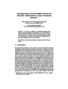
3.1. A system of communicating FSMs Many complex systems are typically specified as a collection of communicating components. We consider here a system that consists of two communicating FSMs (SCFSM) (see Fig.1). We let the alphabets I1∪I2 and O1∪O2 represent the externally observable input/output actions (or messages) of the system, while the alphabets E1 and E2 represent the internal (hidden) input/output interactions between the two component FSMs. The FSMs communicate asynchronously via bounded internal queues where messages are stored. We consider the case of multiple stimuli [KSK02] where simultaneously two external inputs (multiple stimuli input) from the environment can be sent to both component machines. Moreover, in response to an input each component machine can produce a pair of outputs, one to the environment
and one to other component machine [TKS03]. We also assume that the system works in a slow environment [PYBD96]. This means that the next external input is applied only when the processing of previous external input by the system has been completed, i.e. when the internal queues become empty. Due to this assumption, if the system queues are empty and a multiple stimuli input is applied to the system, each internal queue can get a message. After the processing an internal message by one of the component machines one of the queues will become empty while another message can be added to the input queue of the other component machine. In this case the component machine that has two messages in its input queue processes one of these messages and as a corollary it can produce an input message to the other component machine. Thus, at any time, the length of the input queues will not exceed two. Under the above assumptions, the collective behavior of the two communicating FSMs can be described by a finite composed machine that describes the observable behavior of the system. The composed machine is obtained from a reachability graph [Wes78, BoSu80, BrZa83] that described the collective behavior of the system components in terms of internal and external actions of the system. In the following subsection we give the details of building a reachabilty graph and a composed machine. I1
O1
I2
O2
C12
A1
E1 E2
A2
C21
Fig.1 A system of two communicating finite state machines We note that after submitting an appropriate external input to the system, i.e. when the input queues are empty, the two component machines can carry on an infinite internal dialogue. In this case we say that the system falls into a livelock. Here, as in the single stimuli mode, a livelock of the system can result in the absence of an external output at least at one external port. Moreover, differently from the single stimuli mode [PYBD96], we also have another type of livelocks that occurs when one of the system components produces an infinite external sequence. If the system can fall into livelock under an appropriate input sequence then the composed machine enters the designated Livelock state with the designated livelock output [STEY03]. In this case, the corresponding transition of the composed machine is called suspicious and takes the machine to the designated Livelock state.
3.2. Reachability graph and composed FSM Formally, we consider a system of two communicating FSMs A1=〈Q,I1∪E2,O1×E1,h 1 ,q0〉 and A2=〈T,I2∪E1,O2×E2,h 2 ,t0〉 (Fig. 1) where the channel C12 (C21) is a FIFO queue linking the FSM A1 (A2) to the FSM A2 (A1). Thus, the FSM A1 has I1∪E2 as the set of inputs and O1×E1 as the set of outputs and the FSM A2 has I2∪E1 as the set of inputs and O2×E2 as the set of outputs. The alphabets I1, I2 and O1, O2 represent the externally observable input/output actions of the system, while the alphabets E1 and E2 represent the internal input/output interactions between
the two component machines that are non-observable (hidden). As in [PYBD96] we assume that all the alphabets are pair-wise disjoint. In order to deal with the situation where a component FSM in response to an input produces only an internal or an external output, we assume that the alphabets O1, E1, O2 and E2 include the silent message ε. Thus, the output pair (o,ε)∈O1×E1 corresponds to the situation where A1 produces only the external output o to the environment. To describe the joint behavior of a SCFSM we build a reachability graph G [Wes78, BoSu80, BrZa83]. The reachability graph G is a pair (V,E), where the set V of vertices represents the set of so-called global states of the system. The set E of edges represents transitions between global states. A global state of a SCFSM is a 4tuple (q,t,c12,c21) where q∈Q, t∈T, c12∈E12 and c21∈E22 are the contents of the internal queues C12 and C21, respectively, where E2 is the set of all sequences over the alphabet E of length at most two. A global state is called stable if all internal queues are empty. Otherwise, it is called transient. Under the above assumptions, a component machine of SCFSM can produce a pair of outputs in response to an input. By this reason, given a stable state and an external input, the system can produce a pair of external output sequences. In case of finite dialogue, the length of these sequences cannot exceed an appropriate integer k. In case of infinite dialogue, the system falls into a livelock, i.e. the system enters the designated Livelock state. In this case at least one component machine of the system does not produce an external output or produces an infinite sequence of external outputs. As usual we assume that a livelock can be detected by means of a timer. In other words, if after an appropriate time period the system does not produce any external output sequence in at least one of its external ports or it continues producing output actions, then we conclude that the system falls into a livelock. Given a SCFSM A1 and A2, in order to derive the composed machine we construct a reachability graph G that describes the joint behavior of A1 and A2 under (single) inputs of the sets I1 and I2 and under multi stimuli inputs of the set I1×I2. The externally observable behavior of the SCFSMs, i.e. the composed machine A1◊A2, can be obtained from the reachability graph by hiding all internal actions and pairing inputs with corresponding output sequences of length up to k similar to the single stimuli model [PYBD96]. Each transition of the FSM A1◊A2 has i1i2∈I1×I2, i1∈I1, or i2∈I2 as an input label and as an output label it has the designated livelock output, in case the transition leads to the designated Livelock state, or a pair of finite output sequences (β , γ ) of length at most k, where β is defined over the external alphabet O1 and γ is defined over the external alphabet O2. Given a state of the composed machine A1◊A2 and an external (single or multiple stimuli) input, if there exists a path in the reachability graph that starts at the state and includes a cycle with only transient states, then the system falls into livelock at the state when the input that labels the head transition of the path is applied. In this case, the composed machine includes a corresponding suspicious transition to the designated livelock state labeled with the given input and the designated livelock output. Thus, the composed FSM A1◊A2 under a given input either transits to the livelock state producing the livelock output or it transits to another global state producing a pair of finite output sequences.
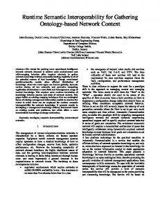
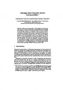
As an example, consider the FSMs MM1 and MM2 shown in Figures 2 and 3 below. The sets of external inputs and outputs of MM1 are {x1, ε} and {y1,ε}, and the sets of external inputs and outputs of MM2 are {x2, x3, ε} and {y2,y3,ε}. The set of internal inputs of MM1 (internal outputs of MM2) is {v1,v2,ε}, and the set of internal inputs of MM2 (internal outputs of MM1) is {u1,ε}. Figure 4 shows a part of the reachability graph of FSMs MM1 and MM2. For example, from state 1a under the input (x1x3) the system can reach the stable state 2b and produce the output pair (ε,y2 y2) or it can fall into livelock. Thus, in the corresponding composed machine MM1◊MM2, we add an outgoing suspicious transition from state 1a to the livelock state labeled with the input/output (x1x3)/Livelock. Similarly, we include the following suspicious transitions in MM1◊MM2. From state 1b, transitions x1/Livelock and x2/Livelock. From state 2b, transitions x2/Livelock and (x1x2)/Livelock. The composed machine MM1◊MM2 is shown in Figure 5 below.
Fig. 2. FSM MM1
Fig. 3. FSM MM2
Fig. 4. Part of reachability graph
(1)
(2)
1a
(4)
(8)
(9) (11)
Livelock (6)
(5)
(13) (16)
2a
(3)
1b
(7) (12) (10) (14)
2b
(17)
(1) x2/(ε,y3); x3/(ε,y2); x1x3/(y1,y3) (2) x3/(ε,y3); x1x3/(y1,y3); x1x3/(ε,y2y3) (3) x1/(y1,ε),(ε,y2); x2/(y1,ε),(ε,y2); x3/(ε,y2); x1x2/(y1y1, ε); x1x2/(y1,y2); x1x2/(ε,y2y2); x1x3/(y1,y2)
(15)
(4) x2/(y1,ε); x1/(y1,ε); x1x2/(y1y1,ε); x1x2/(y1,y2); (5) x1x3/(y1,y3) (6) x1/(ε,y2); x1x2/(ε,y2y3); x1x3/(ε,y2y3); x1x3/(ε,y2y2); x1x3/(y1,y3) (7) x2/(y1,ε); x3/(y1,ε); x1x2/(y1y1,ε); x1x3/(y1y1,ε) (8) x1x3/Livelock (9) x1x2/Livelock; x1/Livelock; x2/Livelock (10) x1/(y1,ε),(ε,y2); x2/(ε,y2); x3/(ε,y2); x1x2/(y1y1,ε); x1x2/(y1,y2); x1x2/(ε,y2y2) (11) x2/(y1,ε),(ε,y2); x1x2/(y1y1,ε); x1x2/(y1,y2) (12) x1x2/Livelock; x2/Livelock (13) x1/(y1,ε); x2/(y1,ε) (14) x3/(ε,y3); x1x3/(y1,y3) (15) x2/(y1,ε); x1x2/(y1y1,ε) (16) x1/(y1,ε); x2/(ε,y3); x3/(ε,y2); x1x2/(y1,y3); x1x3/(y1,y2) (17) x1/(y1,ε); x2/(y1,ε),(ε,y2); x1x2/(y1y1,ε); x1x2/(y1,y2) Fig. 5. The composed FSM MM1◊MM2 The composition of two component machines can be partial or complete, deterministic or non-deterministic depending on these machines. Here we note that differently the single stimuli mode in the multi stimuli mode at each transient state one of the component machines can be faster than the other in producing a response to an applied input or both component machines can produce simultaneously their outputs. However, according to the following proposition, if the component machines are deterministic then their composed machine is also deterministic. Proposition 1. If the component machines A1 and A2 of a SCFSM are deterministic and the system does not fall into a livelock, then the composed FSM A1◊A2 is deterministic. Proof. Let (q,t,ε,ε) be a stable state of the reachability graph. It means that the deterministic FSM A1=(Q,I1∪E2,O1×E1,ψ 1 ,ϕ1 ,q0) is at state q, the deterministic FSM A2=(T,I2∪E1,O2×E2,ψ 2 ,ϕ2 ,t0) is at state t, and both channel queues are empty. Consider the mode “multiple external input”, i.e. the case when the composed FSM has an input i1i2∈I1×I2. The cases with a single stimulus from the environment can be proved in the same way. Let under the input i1 the FSM A1 at a state q produce the output pair (o1,e1), i.e. ϕ1 ( q, i1) = (o1,e1), and the input i1 takes the FSM A1 from state q to state q’, i.e. ψ 1 (q, i1) = q'. Let under the input i2 the FSM A2 at a state t produce the output pair (o2,e2), i.e. ϕ2 (t, i2) = (o2,e2), and the input i2 takes the FSM A2 from state t to state t’, i.e. ψ 2 ( t, i2) = t'. Then in the reachability graph there is the edge labeled with i1i2/(o1,e1)&(o2,e2) which leads from the node (q,t, ε,ε) to the node (q',t',e1,e2).
Thus we have the transient node (q',t',e1,e2). Since the FSM A1 and the FSM A2 communicate asynchronously then there are three cases: the FSM A1 starts to work first, the FSM A2 starts to work first, and the FSMs work simultaneously. To prove the statement it is enough to show that in all cases the system enters one and the same state with a single pair of external outputs. Let under the input e2 the FSM A1 at state q' produce the output pair (o3,e3), i.e. ϕ1 ( q',e2) = (o3,e3), and the input e2 takes the FSM A1 from state q' to state q'', i.e. ψ 1 (q',e2) = q''. Let under the input e1 the FSM A2 at a state t' produce the output pair (o4,e4), i.e. ϕ2 (t',e1) = (o4,e4), and the input e1 takes the FSM A2 from state t' to state t'', i.e. ψ 2 ( t',e1) = q''. Let the FSM A1 starts to work first. Then in the reachability graph there is the edge labeled with e2/(o3,e3) which leads from the state (q',t',e1,e2) to the state (q'', t', e1e3, ε). Since channel queue C21 is empty then a stimulus for a component machine is taken from a queue of the channel C12. Then in the reachability graph there is the edge e1/(o4,e4) which leads from the node (q'', t', e1e3, ε) to the node (q'', t'', e3,e4). Thus we have the transient node (q'', t'', e3, e4) while an external output (o3,o4) is produced. Let the FSM A2 starts to work first. Then in the reachability graph there is the edge e1/(o4,e4) which leads from the node (q',t',e1,e2) to the node (q', t'', ε, e2e4). Since channel queue C12 is empty then a stimulus for a component machine is taken from a queue of the channel C21. Then in the reachability graph there is the edge e2/(o3,e3) which leads from the node (q', t'', ε, e2e4) to the node (q'', t'', e3,e4). Thus we again have the transient node (q'', t'', e3, e4) and the external output (o3,o4). Let now FSMs A1 and A2 work simultaneously. Then in the reachability graph there is the edge e1e2/(o4,e4) & (o3,e3) which leads from the node (q',t',e1,e2) to the node (q'', t'', e3, e4) and the external output (o3,o4). Thus in the reachability graph there are three different paths and each of them leads from the node (q',t',e1,e2) to the node (q'', t'', e3, e4) with the same external output (o3,o4). Hence, under an arbitrary multiple input the composed FSM can move from a state to the only state and produce only one output pair, i.e. the composed machine is deterministic.
4. Testing Livelocks We recall that one of the purposes of interoperability testing is to test if the joint behavior of two component implementations has no livelocks. As usual, to guarantee complete fault coverage we need a formal model of possible faults. In general the traditional fault model [PYB96] is used. However, in order to test for livelocks, we do not need the specification of the whole system. Accordingly, in the following we introduce a more general fault model and method for complete test derivation w.r.t. this model.
4.1 A Fault Model for Livelock Testing Often protocol specifications contain optional commands or options that are not specified or parameters that have no restrictions on their implementations. As a corollary, such specifications are not complete and are described by partial FSMs. Thus, hereafter, we consider two partial deterministic component specifications A1 and A2. The implementations of A1 and A2 are usually tested in isolation. Since A1 and A2 are partial, their implementations are usually tested using the quasiequivalence conformance relation. According to this relation, for each defined behavior of A1 (or A2) the corresponding implementation should have the same behavior. However, the undefined transitions of A1 and A2 can be completed in different ways by different vendors. When there are no restrictions imposed, the designers can complete the undefined transitions according to their preferences. This can cause a livelock when an input sequence that traverses undefined transitions is applied to the system implementation. Formally, we consider two partial component specifications A1 and A2 and we assume that their implementations are complete and deterministic. We let ℜ1 and ℜ2 denote the sets of all possible complete deterministic implementations of A1 and A2. We assume that each machine of the sets ℜ1 (ℜ2) is quasi-equivalent to the corresponding partial specification A1 (A2). An implementation system is the composition of two complete deterministic FSMs of the sets ℜ1 and ℜ2, i.e. ℜ = {Imp1◊Imp2 | Imp1∈ℜ1, Imp2∈ℜ2}. Thus, the set ℜ is the set of all possible system implementations. We say that a test suite is complete w.r.t. the fault model if the test suite detects each system implementation that falls into a livelock under some input sequence. Usually a livelock is detected by means of a timer. Therefore, in order to detect a livelock, it is sufficient to traverse a transition of an implementation system that leads to a livelock. In other words, a test suite is complete w.r.t. the fault model if for each possible system implementation Imp of the set ℜ that has transitions leading to a livelock, the test suite traverses at least one of these transitions. A straightforward approach for deriving a complete test suite w.r.t. the fault model is to explicitly enumerate all possible system implementations and for each implementation with at least one transition leading to a livelock to derive an input sequence that traverses one of these transitions. However, in order to avoid the explicit enumeration of all possible implementation machines, a mutation machine [KPY99] can be used. The fault domain ℜj of a component machine Aj, j = 1,2, can be described by a complete mutation machine MMj. This mutation machine is obtained from Aj by completing its undefined transitions in all possible ways, i.e. for each undefined transition of Aj we add new transitions to all possible states with all possible outputs, or due to the imposed restrictions. Given a mutation machine MMj, j=1,2, the set of all deterministic submachines of MMj coincides with the set ℜj. That is the set ℜ1 = Sub(MM1) and the set ℜ2 = Sub(MM2). Thus, each possible implementation system is a submachine of the machine MM ≅ MM1◊MM2. Accordingly, we can use the fault model [STEY03] for livelock testing. In the following subsection we present a method for deriving a complete test suite w.r.t. the model without enumerating submachines of the mutation machine MM.
4.2 Test Suite Derivation Method State s of an FSM A is reachable if there exists an input sequence that takes the FSM from the initial state to s. If state s of FSM A is reachable while traversing only deterministic transitions then s is said to be deterministically reachable. In this case, we call an input sequence that takes A from the initial state to s while traversing only deterministic transitions a deterministic transfer sequence for state s. The set of deterministic transfer sequences for all deterministically reachable states of A is called a deterministic cover set of A. Moreover, given the FSM MM≅ MM1◊MM2, we let MMNoLTr denote the submachine obtained from MM by deleting all transitions leading to the Livelock state. In order to derive a complete test suite w.r.t. the fault model , we consider the following cases. Extreme Case 1. There are no suspicious transitions in MM. That is, the composition of any two complete sub-machines of MM1 and MM2 does not fall into livelock. In this case, we do not need to test for livelocks. Extreme Case 2. Each state of the submachine MMNoLTr is reachable via deterministic transitions. In this case, for each outgoing suspicious transition of the state pair st of MM labeled with the input x, we include in the test suite the input sequence r.αx where α is an input sequence that deterministically takes the submachine MMNoLTr from its initial state to the state st. General Case. Generally, not each suspicious transition of the submachine MM is deterministically reachable. In this case, we derive a complete test suite as follows. Algorithm 1. Test suite derivation algorithm Input: A non-deterministic mutation machine MM ≅ MM1◊MM2 Output: A complete test suite w.r.t. the fault model Step 1. Determine the minimal length deterministic cover set D of the submachine MMNoLTr, let m=|D|. Moreover, let αj∈D be a deterministic transfer sequence for state sj. Step 2. For each deterministically reachable state sj of MMNoLTr we derive a traversal set Tr(sj) in the following way. Let α be an input sequence such that the length of α is not greater than n-m+1, where n is number of states of the FSM MM. We include α into Tr(sj) if there exists an output sequence β of MM to α such that the following conditions hold: • the trace α/β does not traverse twice a state of MM, • α/β does not traverse a deterministically reachable state of MMNoLTr, • the last transition traversed by α/β is suspicious, Step 3. For each deterministically reachable state sj of the submachine MMNoLTr we derive the set Ej = r.αj.Tr(sj). The test suite is the union of the sets Ej over all deterministically reachable states.
Proposition 2. The test suite returned by Algorithm 1 is complete w.r.t. the fault model . As an example, consider the mutation machine MM = MM1◊MM2 shown in Figure 5. States 1a and 2b are deterministically reachable from the initial state through the inputs ε and x1. Thus, we derive the traversal sets for the states 1a and 2b. The input sequences in the traversal set for state 1a have to traverse the outgoing suspicious transitions of state 1b. These are transitions labeled with the inputs x1, x2 and (x1x2). State 1b can be reached from state 1a under the inputs x3 and (x1x3). Therefore, Tr(1a)={x3.x1, x3.x2, x3.(x1x2), (x1x3).x1, (x1x3).x2, (x1x3).(x1x2)}. Moreover, the input sequences of the traversal set for state 2b have to traverse the outgoing suspicious transitions of 1b. In addition, they have to traverse the outgoing suspicious transitions of state 2b. These are the transitions labeled with the inputs x2 and (x1x2). State 1b can be reached from state 2b under the inputs x2 and x1x2. Thus, Tr(2b)={x1, x2, (x1x2)} ∪ {x2.x1, x2.x2, x2.(x1x2), (x1x2).x1, (x1x2).x2, (x1x2).(x1x2)}. Therefore, Algorithm 1 returns the complete test suite, {r.x3.x1, r.x3.x2, r.x3.(x1x2), r.(x1x3).x1, r.(x1x3).x2, r.(x1x3).(x1x2)} ∪ {r.x1.x2, r.x1.(x1x2), r.x1.x2.x1, r.x1.x2.x2, r.x1.x2.(x1x2), r.x1.(x1x2).x1, r.x1. (x1x2).x2, r.x1.(x1x2).(x1x2)}.
5. Testing w.r.t. specification If a system implementation is free of livelocks, we are still required to test if it satisfies the specification. Given the partial specifications A1 and A2 of the communicating protocol entities and their corresponding implementations Imp1 and Imp2, we assume that Imp1 and Imp2 are deterministic, complete, tested in isolation and found quasi-equivalent to A1 and A2. Thus, we assume that the joint behavior of the complete protocol implementations (i.e. the system implementation) is checked w.r.t. the defined behavior of the partial specifications. Given the specification Spec of the whole system, we are required to determine if Imp1◊Imp2 ≅ Spec. Here we note that Spec of a given SCFSM can be obtained in various ways. For example, Spec can be derived based on our knowledge how the whole SCFSM has to work. In this paper Spec is assumed to be deterministic and complete1. However, the components implementations can be completed in different ways by different vendors. Since Imp1 and Imp2 were tested in isolation and found quasi-equivalent to A1 and A2, we assume that Imp1◊Imp2 is quasi-equivalent to Spec. However, the behavior of the complete implementation machine Imp1◊Imp2 has also to be tested w.r.t. the specification under undefined input sequences. In this case, the incremental testing methods [EYB02, Elf02] are known to return shorter test suites than the W[Chow78], Wp[Fuj91], or HIS[PYLD93] methods. If the fault domain is represented as the set of deterministic submachines of an appropriate mutation 1
In general case an implementation system has to be tested w.r.t. the reduction relation since there can occur several options of the behavior under undefined input sequences.
machine, then the length of a test suite returned by incremental testing methods is known to essentially depend on the number of deterministic transitions in the mutation machine. By this reason, in this paper, we divide the fault domain into three parts assuming that the implementation of at most one component machine can be faulty or that both component implementations can be faulty. To do this we augment the given partial specification machines A1 and A2 according to our preference and we obtain CompA1 and CompA2 as the complete forms of A1 and A2. In the following two subsections we present a fault model and a test derivation method based on the above assumptions. 5.1 A Fault Model for Testing w.r.t. Specification Let Imp1 and Imp2 be two deterministic complete implementations of the partial deterministic protocol specifications A1 and A2. We recall that Imp1 and Imp2 are submachines of the mutation machines MM1 and MM2. In order to determine if the joint behavior of Imp1 and Imp2, i.e. Imp1◊Imp2, is equivalent to the reference specification Spec, we use a traditional fault model , where the fault domain is the set Sub(MM) of all deterministic submachines of the mutation machine MM ≅ MM1◊MM2. Here we reasonably assume that both implementations can be faulty. A test suite is complete w.r.t. the fault model if the test suite detects each system implementation that is not equivalent to Spec. In the following subsection we derive a complete test suite w.r.t. to this fault model. 5.2 Test Derivation Method In order to generate a complete test suite for the fault model is , one can use the known W[Chow78], Wp[Fuj91], or HIS[PYLD93] test derivation methods assuming an upper bound m on the number of states of the implementation system is given. This bound can be calculated as the number of states in the composed system A1◊A2. However, these methods generate tests not only for Sub(MM) but also for every possible implementation with up to m states. Thus, we need a more appropriate approach that generate tests for the domain fault domain Sub(MM) taking into account the fact that Imp1 and Imp2 are tested in isolation and found quasi-equivalent to A1 and A2. In other words, we need an approach that uses the incremental testing methods presented in [EYB02,Elf02]. These methods generate tests that check the untested parts of an implementation utilizing some information from the tested parts. However, since the lengths of the test suites generated using the incremental methods significantly depend on the number of nondeterministic transitions of MM, which can be too many, we consider two subdomains of the fault domain Sub(MM). Then, we generate tests, using the incremental testing methods, for one subdomain and we reduce, using the reduction algorithm presented in [EPYB03], the other domains based on the expected behavior of the implementation system (or System Under Test (SUT)) to these tests. In other words, we delete from other subdomains nonconforming submachines that are detected with the derived part of a test suite. Particularly, we consider the fault subdomains Sub(MM1◊CompA2) where
Imp2 is assumed to be fault free, i.e. Imp2≅ CompA2, and the subdomain Sub(CompA1◊MM2), where Imp1 is assumed to be fault free. Then, we generate incremental tests for the subdomain Sub(MM1◊CompA2) and we use these tests to reduce the mutation machines MM and MM1◊CompA2. Reducing these machines is done based on the expected output behavior of the SUT to these tests using the algorithm presented in [EPYB03]. Then, we derive tests for subdomain Sub(CompA1◊MM2) and we use these tests to reduce MM. Finally, we generate tests for the fault domain Sub(MM’), where MM’ is a reduced submachine of the initial mutation machine MM. The details of the method are presented in the algorithm given below. Here we note that in order to assess the gains of using incremental testing v.s. complete testing of the whole system implementation, we have implemented and experimented with the methods presented in [EYB02]. The experiments showed that when the tested part is up to 95% of the whole implementation, on average, the HIS based test suites are 36 times bigger than the corresponding incremental test suites. Moreover, these test suites are on average 11.3, 6.1, and 4.0 times bigger when the tested parts are up to 90%, 85%, and 80% respectively. Moreover, the experiments showed that the ratios of the lengths of the test suites do not significantly depend on the size of specifications. Algorithm 2. Test suite derivation algorithm Input: A specification of the whole system Spec, partial deterministic components A1 and A2, and their completed forms CompA1 and CompA2. Output: A complete test suite TS w.r.t. the fault model (1a) and (2a)- (x, i)/(yyy, o)> (1a). The characterization set W = {x} of Spec does not traverse these transitions, accordingly, according to the so-called Case-1 of [EYB02], we derive the incremental tests riix, ri(x,i)x for testing these transitions. If the SUT is equivalent to Spec, the expected behavior of the SUT to the input sequences of TS1 is ri/(y, o)i/(yy,o)x/(y,o) and ri/(y, o) (xi)/(yyy,o)x/(y,o). Afterwards, using these sequences, in Step 3, we reduce CompA1◊MM2 of Fig. 8.2. The reduced machine is that of Fig. 8.2 without underlined transitions. Afterwards, for the untested (i.e. non-deterministic) transitions of CompA1◊MM2, we determine the corresponding transitions in Spec. This is transition (1a)-(x, i)/(yy, oo)->(2a). In order to test this transition, we apply again the so-called Case-1 of [EYB02] that derives the input sequence TS2 = {r(x,i)x}. The expected output of a fault-free SUT to r(x,i)x is r.x,i/(yy, oo).x/(y, ε). Finally, in Step 4, using TS1 and TS2 and their expected outputs, we reduce the mutation machine MM. In this example, TS1 and TS2 completely reduce MM, i.e., all transitions of MM become deterministic and MM is equivalent to Spec in Fig. 6.3. Thus, the test suite TS1∪TS2 can be used to check if Imp1◊ Imp2 ≅ Spec. The total length of the union of the test suites is 11, while the length of the test suite derive using the W method for the whole specification Spec is 18.
6. Conclusion In this paper, we have proposed two fault models and methods for the derivation of interoperability test suites when the system implementation is given in the form of two deterministic communicating finite state machines. A test suite returned by the first method determines if the implementation is free of livelocks. If the implementation is free of livelocks, the second method returns a test suite that checks if the implementation conforms to the specification. Acknowledgement The authors would like to thank Rita Dorofeeva at Tomsk State University for implementing and experimenting with the incremental testing methods.
References [BrZa83] D.Brand and P.Zafiropulo, On communicating finite state machines, J. ACM 30(2), (1983) 323-342. [BoSu80] G. v. Bochmann, and C. A. Sunshine, “Formal methods in communication protocol design”, IEEE Trans. on Comm., Vol 28, 1980, pp 624-631. [Chow78] T. S. Chow, “Test Design Modeled by Finite-State Machines,” IEEE Trans. SE, vol. 4, no.3, 1978, pp. 178-187. [EYB02] K. El-Fakih, N. Yevtushenko and G.Bochmann, Protocol re-testing methods, Proc. of the IFIP 14th International Conference on Testing of Communicating Systems, 2002, Berlin, Germany, 19-22. [EPYB03] K. El-Fakih, S. Prokopenko, N.Yevtushenko, G. Bochmann, Fault diagnosis in extended finite state machines. Proc. of the IFIP 15th International Conference on Testing of Communicating Systems. Lecture Notes in Computer Science 2644, pp. 197-210, 2003. [Elf02] K. El-Fakih, Protocol retesting and diagnostic testing methods, Ph.D. Thesis, University of Ottawa, 2002. [Fuj91] S. Fujiwara, G. v. Bochmann, F. Khendek, M. Amalou, and A. Ghedamsi, “Test Selection Based on Finite State Models,” IEEE Trans. SE, vol. 17, no. 6, 1991, pp. 591-603. [KSK00] S.Kang,, J.Shin, M.Kim, Interoperability Test Suite Derivation for Communication Protocols. Computer Networks, 32 (2000) 347-364. [KPY99] I. Koufareva, A. Petrenko, N. Yevtushenko, Test generation driven by userdefined fault models, Proceedings of IFIP TC6 12th International Workkshop on Testing of Communicating Systems, Hungary, 1999. – pp. 215-233. [KSK00] S.Kang, J.Shin, M.Kim, Interoperability Test Suite Derivation for Communication Protocols. Computer Networks, 32 (2000) 347-364. [PYB96] A. Petrenko, N. Yevtushenko, G. v. Bochmann. Fault models for testing in context. FORTE’96. [PYBD96] A. Petrenko, N. Yevtushenko, G. v. Bochmann, and R. Dssouli, Testing in context: framework and test derivation, Computer communications, Vol. 19, pp. 1236-1249, 1996. [PYLD93] A. Petrenko, N. Yevtushenko, A. Lebedev, and A. Das, “Nondeterministic State Machines in Protocol Conformance Testing,” Proc. of the IFIP 6th IWPTS, France, 1993, pp. 363-378. [SKC02] S.Seol, M.Kim, and S.T.Chanson, Interoperability Test Generation for Communication Protocols based on Multiple Stimuli Principle, Proceedings of the IFIP 14th Inter. Conf. TestCom2002, Berlin, pp.151169. [STEY03] N. Spitsyna , V. Trenkaev, K. El-Fakih, and N. Yevtushenko, FSM based interoperability testing-work in progress, presented as work in progress at FORTE 03, Berlin, Germany, Sept. 2003. [TKS03] Trenkaev V., Kim M., and Seol S. Interoperability Testing Based on a Fault Model for a System of Communicating FSMs // Lecture Notes in Computer Science, Vol. 2644: D.Hogrefe, A.Wiles (Eds.), Testing of Communicating Systems, Proceedings, 2003, pp. 226-241
[VBT01] C. Viho, S.Barbin and L. Tanguy, Towards a formal framework for interoperability testing, Proceedings of the 21st Inter. Conf. FORTE 2001, Korea, pp.51-68. [West78] C.H. West, An automated technique of communication protocols validation, IEEE Trans. Comm., 26 (1978) 1271-1275.