Texture-based wireframe rendering with different thickness values (Ï) on a Mini Cooper model. ... Keywords-wireframe rendering; antialiased lines; mipmap-.
Texture-based wireframe rendering Waldemar Celes and Frederico Abraham Tecgraf/PUC-Rio – Computer Science Department Pontifical Catholic University of Rio de Janeiro, Brazil Email: {celes, fabraham}@tecgraf.puc-rio.br
(a) σ = 0.5
(b) σ = 1.0
(c) σ = 2.0
(d) σ = 4.0
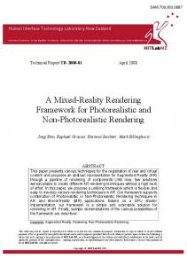
Figure 1. Texture-based wireframe rendering with different thickness values (σ) on a Mini Cooper model. On the right, the wireframe is drawn in isolation.
Abstract—This paper revisits the problem of wireframe rendering, which, at first, appears to be an easily solved problem. However, the conventional solution is inefficient and does not result in high-quality images. Recently, graphics hardware programming has been employed to achieve highquality solid line rendering. In this paper, we present a simpler and faster technique for wireframe rendering based on texture mapping. Our technique does not require (but can benefit from) graphics hardware programming and thus can be easily integrated to existing rendering engines, while resulting in accurate, high-quality, antialiased, and still versatile, wireframe drawing. Keywords-wireframe rendering; antialiased lines; mipmapping; geometry shader
of a two-pass rendering algorithm. The first pass renders the polygons with a small depth offset, and the second renders the lines. This solution is inefficient and does not result in high-quality images. For years, this conventional algorithm was assumed as a standard for real-time applications. Previous proposals for line drawing based on textures do not preserve line thickness [1], [2]. A few alternatives based on the stencil buffer or the A-buffer were proposed but lack efficiency [3], [4]. Recently, Bærentzen et al. [5], [6] proposed a new efficient algorithm based on graphics hardware programming.
I. I NTRODUCTION Wireframe rendering is important for several applications, including CAD, solid modeling, non-photorealistic rendering, and technical illustration. Rendering the wireframe is important for revealing structural information of the underlying mesh used to model the object. This is especially true in scientific visualization of models submitted to numerical simulations, where the quality of the mesh is of great significance and thus has to be inspected. An application can choose to render the wireframe in isolation or combined with a shaded surface. Wireframe rendering is conceptually an easy problem. The goal is to visualize the wireframe of a mesh, i.e. to render the edges of a mesh. In practice, this turns out to be a tricky problem because the pixels resulting from the rasterization of lines do not always match the border pixels resulted from the rasterization of polygons. The conventional solution consists
Figure 2. High-quality wireframe rendering on a plane model with different thickness values.
In this paper, we revisit the problem of wireframe rendering and propose a new single-pass algorithm based on texture mapping. Our technique is simpler and faster than previous ones, while resulting in accurate, high-quality,
antialiased images. We have used it in different industrial applications. It does not require (but can benefit from) graphics hardware programming and is still versatile enough to handle arbitrary line thickness values and attenuation (depth cueing). Figure 1 shows some images achieved with our technique for different thickness values. In Figure 2 the rendered image is enlarged to illustrate the achieved antialiased lines. Our technique also handles the rendering of lines decoupled from the mesh, which has some important applications, such as the rendering of grids over curved surfaces or isolines of scalar fields in scientific applications. The rest of this paper is organized as follows. Section II reviews the problem of wireframe rendering and describes previous proposals. Section III presents our texture-based proposal in detail, and a performance comparison is shown in Section IV. Section V discusses the use of our technique for drawing lines decoupled from the mesh geometry. Finally, concluding remarks are drawn in Section VI. II. R ELATED WORK Rendering high-quality wireframe on top of shaded surface is more involving than it appears at first. The main problem is due to having different algorithms for line and polygon rasterization. Bærentzen et al. [7] illustrated this problem using the image in Figure 3. The highlighted pixel belongs to the edge AB and also to the polygon border. However, the depth values at the center of this pixel resulted from the two (line and polygon) rasterization algorithms differ: the depth value of the line fragment is computed interpolating only vertices A and B, while the depth value computation of the corresponding polygon fragment also considers vertex C. Due to this difference, one cannot ensure which fragment will be rendered in front.
B
A
C
Figure 3. The depth value of a line fragment differs from the corresponding depth value of a polygon fragment [7].
The conventional, two-rendering-pass algorithm alleviates the depth value conflict by adding a small z-bias to the polygon fragments. Although widely used in commercial applications, this algorithm is inefficient because it requires two rendering passes, doubling the geometry load; also, line rasterization itself is not efficiently implemented in some graphics cards. The algorithm is inaccurate because there
is no standard z-bias value that completely eliminates the visibility conflict [8]. Moreover, in general, this algorithm produces aliased lines. In order to disambiguate the visibility conflict between line and polygon fragments, Herrell et al. [3] proposed to use the stencil buffer. Their algorithm produces accurate images but requires rendering each triangle separately, thus being inefficient for real-time applications. Wang et al. [4] proposed to solve the visibility conflict using an A-buffer, which is not supported on modern graphics cards. More recently, Bærentzen et al. [5], [6] proposed a single-pass wireframe rendering algorithm based on graphics hardware programming. Their proposal does not use the line primitive at all; instead, the edges are drawn as part of the polygon rasterization. The general idea is to use a fragment shader that evaluates the distance of each fragment to the closest edge. If this distance is smaller than a given threshold (the line thickness value), the fragment is colored with the wireframe color. As a result, their algorithm is able to render high-quality solid wireframes and presents better performance than the conventional two-pass approach. To compute the raster distance from each fragment to the edges, a geometry shader may be employed: for each vertex, the distance to the opposite edge (considering triangle primitives) is computed and assigned as a texture coordinate. The distance values are then interpolated by the rasterizer for each fragment. Although conceptually simple, this algorithm requires graphics hardware programming and faces the challenge of computing distance values after the projection transformation. When the vertex is close or behind the viewer, its distance in viewport space cannot be computed [9]. In this paper, we present a new algorithm for wireframe rendering. Like Bærentzen et al. [5], [6], we render the edges as part of the polygon rasterization but, instead of relying on graphics hardware programming, we simply use textures. As a result, our algorithm presents better performance, is easier to be implemented, and still preserves image quality. The use of textures for line rendering is not new. Haeberli and Segal [1] suggested different ways for using textures for anti-aliased line drawing but did not identify any way for efficient wireframe rendering. Kuschfeldt and Holzner [2] focused on finite element mesh rendering and proposed the use of a two-dimensional texture for drawing the border of quadrilateral elements (triangular elements were drawn as collapsed quadrilaterals). Similar to ours, their proposal draws the mesh in a single rendering pass but does not preserve line thickness. Also, their proposal does not render meshes in an efficient way. Later, Rose and Ertl [10] presented a specialized system for applying level-of-detail techniques over large finite element models. In order to draw an approximation of the original mesh wireframe over a simplified surface patch, they proposed to code distances to the edges in a 2D texture, using dependent texture lookup to
1.0
render the lines. Their proposal is specifically designed for rendering simplified quasi-structured quadrilateral meshes. III. P ROPOSED TEXTURE - BASED TECHNIQUE Our algorithm renders the wireframe in a single-rendering pass and basically consists in using texture mapping to draw edges together with polygon rasterization. The texture mapping is done using a 1D RGBA texture, the wireframe texture, that represents half of the line (across the thickness direction). Each polygon draws one side of the line, and the complete line is rendered after two adjacent polygons are rasterized. Figure 4a illustrates a texture used to render wireframes with a thickness value equal to 3.0. The alpha channel, which is illustrated in the figure, encodes opacity. In this case, half of the line thickness (a value of 1.5) is represented by setting the alpha value of the last texel to 1.0 and of its neighbor texel to 0.5. Mipmapping is used to ensure that line thickness is preserved despite the size of the primitive when mapped to the screen. At each level of the mipmapping pyramid, the texels representing the wireframe are preserved (Figure 4b). Note that we can use different thickness values, as shown in Figure 1.
s 0.0
1st unit
1.0
0.0 s
1.0
s 1.0
2nd unit
1.0
-1.0
1.0
1.0
s -1.0
1.0
1.0
s
1st unit
-1.0
1.0
2st unit
-1.0
(b) Quad 1.0
1.0
0.0
0.0
3rd unit
(a) Triangle
1.0
1.0
s
s
S
1.0
1.0
1st unit
1.0
1st unit
1.0
(c) Alternative Figure 5.
Texture coordinates.
(a) Texture
level n+2 level n+1 level n
(b) Mipmapping Figure 4.
Opacity values of the wireframe texture.
In order to achieve the desired results, we need to set appropriate texture coordinates when drawing the graphics primitives. For a triangle, we use three texture units, binding the same texture object to all of them. Each texture unit is used for drawing one triangle edge. For a given unit, we set the texture coordinate equal to 0.0 for one vertex and equal to 1.0 for the other two vertices, as illustrated in Figure 5a. For a quadrilateral, it suffices to use two texture units, setting texture coordinates −1.0 and 1.0 to vertices at opposite sides, and mapping the texture with mirroredrepeat wrapping mode (Figure 5b). An alternative approach would be to create an additional vertex in the middle of the primitive and use only one texture unit, rendering a different triangle for each edge of the original primitive, as illustrated in Figure 5c. This is valid for any convex polygon. Naturally,
this strategy imposes an additional load on the geometry stage of the graphics pipeline, but can be useful for applying the method when the number of available texture units is limited. Wireframe can be rendered in isolation or combined with shaded surfaces. When combined with a shaded surface, the texel RGB values are used to encode the wireframe color, and the texture function is set to decal. For representing the wireframe in isolation, we set the texel color to white, using modulate for the first texture unit and texture combiner for adding the contribution of each subsequent unit. The wireframe then receives the color of the primitive (Figure 1d). A. Avoiding saturation One advantage of using texture mipmapping for wireframe rendering is that it naturally ensures line thickness, while achieving high-quality antialiased images. We can also set the mipmapping pyramid in order to avoid saturating the image with the wireframe. This would happen whenever the primitive in viewport space becomes smaller than the line thickness: the whole primitive would be filled with the wireframe color. We avoid this saturation by limiting the thickness in relation to the texture dimension at each level of the mipmapping pyramid. The images shown in this paper
consider a limiting factor of 1/3. This means that, at the highest levels of the pyramid, the thickness value is not honored, but reduced to 1/3 of the level dimension. Figure 6 compares the images obtained without and with this strategy to avoid saturation. B. Mesh rendering For rendering individual primitives, it suffices to activate the texture and set the texture coordinates explicitly. However, for efficient rendering of complex models, we need to pack the vertex’s attributes into arrays and share vertices among primitives to take full advantage of graphics card’s cache. The assignment of texture coordinates as indicated in Figure 5a and 5b perfectly matches the way vertices are arranged in triangle and quad strips, respectively. However, for mesh rendering, we need to duplicate vertices to ensure that, for each primitive, the texture coordinates assigned to the corresponding vertices follow the scheme illustrated in Figure 5. For a triangle mesh, we have devised a simple algorithm to identify and duplicate the vertices that could not be shared by all its incident triangles. The algorithm sets a label 1, 2, or 3 for each vertex of the mesh. Vertices labeled as 1 are assigned texture coordinates s0 = 0.0, s1 = 1.0, and s2 = 1.0 for the first, second, and third texture units in use, respectively. Vertices labeled as 2 are assigned texture coordinates s0 = 1.0, s1 = 0.0, and s2 = 1.0; and vertices labeled as 3 are assigned s0 = 1.0, s1 = 1.0, and s2 = 0.0. In the final mesh, the three vertices incident to each triangle have to be labeled with different numbers, ensuring that all its three edges will be correctly rendered. The algorithm starts by first setting labels 1, 2 and 3 for the incident vertices of a first triangle. Then, it performs a depth-first search visiting each neighboring triangle across the edges. For each new visited triangle, it sets labels to
the unlabeled vertices, choosing labels that do not conflict with the already labeled triangle vertices. If there not exists a non-conflicting label to be assigned to a vertex, the vertex is duplicated and the triangle incidence is updated. For each vertex, the algorithm keeps a list of the corresponding duplicated vertices, so each duplicated vertex can be reused in another, not yet visited, incident triangle. The algorithm was applied considering different models, as illustrated in Table I. As can be noted, for the tested models, the number of duplicated vertices is at most 60% of the original number of vertices in the mesh. These extra vertices impose an additional load on the graphics pipeline, increasing the amount of data transferred to the graphics card and reducing the effective use of vertex caches. However, even with this extra load, our texture-based wireframe rendering algorithm is faster than previous proposals. Model Pitcher Plane Mini Cooper Neptune Magali’s hand Dragon
#T 25,442 55,534 84,944 411,678 396,730 871,306
#V 12,763 36,808 48,252 205,835 198,367 435,545
#V’ 19,348 48,099 69,893 317,363 305,637 692,231
Extra 52% 31% 45% 54% 54% 59%
Table I N UMBER OF ADDITIONAL VERTICES FOR DIFFERENT MODELS .
Nevertheless, we can completely avoid vertex duplication if we use graphics hardware programming. More specifically, we can code a simple geometry shader that automatically generates appropriate texture coordinates, without processing any extra vertices. For each input triangle, the geometry shader outputs the same triangle with its already processed vertices, adding texture coordinates accordingly. The complete GLSL geometry shader code is presented in Figure 7. The gain in performance is significant. Unfortunately, on current graphics cards, the use of a geometry shader still requires the coding of a vertex shader. This may impose difficulties to integrate the use of geometry shader into existing applications. Needless to say, the algorithm to duplicate the vertices is also useful where the geometry shader is not supported. C. Attenuation
Figure 6. Importance of avoiding image saturation: on the top, without limiting line thickness for the highest level of the mipmapping pyramid; on the bottom, with the proposed limiting strategy.
Because the technique proposed by Bærentzen et al. [5], [6] is based on fragment shader, several variations of the method are possible. They have illustrated such a versatility by using attenuation of line intensity and thickness. For line intensity attenuation, the lines fade away according to their distance to the viewer. Accordingly, the thickness attenuation ensures that distant lines appear thinner. Attenuation is also possible and easy to achieve with our technique. For that purpose, we replace the 1D texture by a 2D texture, and use the second (small) dimension to
void main(void) { gl_Position = gl_PositionIn[0]; gl_FrontColor = gl_FrontColorIn[0]; gl_TexCoord[1] = vec4(1.0,0.0,0.0,1.0); gl_TexCoord[2] = vec4(1.0,0.0,0.0,1.0); gl_TexCoord[3] = vec4(0.0,0.0,0.0,1.0); EmitVertex(); gl_Position = gl_PositionIn[1]; gl_FrontColor = gl_FrontColorIn[1]; gl_TexCoord[1] = vec4(0.0,0.0,0.0,1.0); gl_TexCoord[2] = vec4(1.0,0.0,0.0,1.0); gl_TexCoord[3] = vec4(1.0,0.0,0.0,1.0); EmitVertex(); gl_Position = gl_PositionIn[2]; gl_FrontColor = gl_FrontColorIn[2]; gl_TexCoord[1] = vec4(1.0,0.0,0.0,1.0); gl_TexCoord[2] = vec4(0.0,0.0,0.0,1.0); gl_TexCoord[3] = vec4(1.0,0.0,0.0,1.0); EmitVertex(); EndPrimitive(); }
Figure 7.
(a) Without attenuation
GLSL geometry shader.
represent the attenuation effect. For intensity attenuation, we vary the texels’ opacity along the t direction and, for thickness attenuation, we vary the represented line thickness, as illustrated in Figure 8. The s texture coordinates are set as already described, while the t coordinates are set by enabling automatic texture coordinate generation in eye space. Figure 9 illustrates the intensity attenuation effect on a black oil reservoir model. D. Limitations
attenuation
The proposed texture-based technique for wireframe rendering presents the same limitation as Bærentzen et al.’s proposal [5], [9]: it draws only half the silhouette edges. This limitation is intrinsic to the strategy of drawing the lines as part of polygon rasterization. As silhouette edges have only one visible adjacent polygon, the edges appear thinner and aliased.
t s
t s
(a) Intensity Figure 8.
(b) Thickness
2D texture for line attenuation.
(b) With attenuation Figure 9.
Black oil reservoir model with wireframe rendering.
The proposed texture-based approach is only applicable for preserving line thickness in screen space; Bærentzen et al.’s proposal, on the other hand, also allows constant thickness in world space. Also, our approach limits the level of zoom-in without increasing line thickness; one may eventually reach the largest texture dimension in the mipmapping pyramid, thus forcing texture magnification. However, in practice, this does not tend to be an actual limitation. In our code, we have set texture width to 4096, and we hardly have the case where a single primitive is projected with this size on the screen. IV. P ERFORMANCE COMPARISON For performance comparison, we have run a set of computational experiments. We compared the performance
achieved by our algorithm with previous proposals for rendering different triangle meshes. Table II summarizes the obtained results. For reference, the meshes were drawn in retained mode using vertex buffer objects, with back face culling disabled and light model set to two-sided lighting, at a resolution of 1000×800 using OpenGL 2.1 and a NVIDIA GeForce 8800 GTX 768MB graphics card. The table lists the performance, expressed in frames per second (fps), achieved by the following algorithms: • None: The rendering of the model without wireframe representation. • Z-bias: The traditional two-pass algorithm using polygon offset; naturally, lighting was disabled for line drawing. • GPU-based: Our implementation of Bærentzen et al.’s proposal [5] as described in [9], translated to GLSL. • Tex-based: Our proposal on fixed-function graphics pipeline, duplicating the vertices in a pre-processing phase as described. • Tex+GS: Our proposal using the geometry shader, without duplicating vertices. Model Pitcher Plane Mini Cooper Neptune Magalis’ hand Dragon
None 512 351 544 100 99 51
Z-bias 162 96 119 23 23 11
GPU-based 313 205 176 37 44 20
Tex-based 499 341 503 55 86 50
(a) Grid lines over curved surface
Tex+GS 493 336 464 99 98 51
Table II P ERFORMANCE IN FPS FOR RENDERING DIFFERENT TRIANGLE MESHES .
The viewer application used in the tests tended to be rasterizer-bounded for the first, lighter, listed models and geometry-bounded for the last, denser, ones. As can be noted, our technique is faster than previous ones for both configurations. Especially, note that our proposal, with the use of geometry shader, imposes virtually no impact from just rendering triangles. V. L INES DECOUPLED FROM GEOMETRY Our technique can also be used for rendering lines decoupled from the mesh geometry. All we need is to generate the appropriate texture coordinate for mapping the wireframe texture. As a first example, let us consider the display of regularly spaced grid lines on the top of a terrain model, as illustrated in Figure 10a. The grid lines are drawn by projecting the wireframe texture onto the terrain surface. Two texture units are used, one for drawing each set of parallel lines. The texture coordinates are simply determined by enabling appropriate automatic texture coordinate generation in object space. Another example of lines decoupled from the geometry is illustrated in Figure 10b: a black oil reservoir model
(b) Isolines of scalar field Figure 10.
Rendering of lines decoupled from mesh geometry.
is rendered with the isolines of a given scalar field. In this case, it suffices to use one texture unit and to set the value of the scalar field at each vertex as its texture coordinate, with an appropriate texture matrix to control line spacing. Haeberli and Segal [1] had already indicated the use of an unidimensional texture for drawing lines decoupled from the mesh. The challenge, however, is to preserve line thickness. As the lines are decoupled from the mesh geometry, texture magnification may be needed even for small primitives in screen space. In order to illustrate the problem, let us consider the example of drawing the isolines of a scalar field. If the gradient of the scalar field is large, the use of mipmapping, as proposed here, ensures that line thickness is preserved (see Figure 11 a and b). On the other hand, if
Despite its simplicity, we believe the presented technique is a useful tool for computer graphics practitioners, with a wide range of applications. ACKNOWLEDGMENT
Figure 11. Isoline thickness variation: (a, b) for large gradients, the mipmapping preserves line thickness; (c) for small gradients, texture magnification may occur; (d) a geometry shader can be used to avoid texture magnification.
the gradient is too small, texture magnification is called for and lines become thicker, as illustrated in Figure 11c. If geometry shader is available, we can easily (and efficiently) preserve line thickness for small gradients. The problem arises when we have a small range of texture coordinate values over a primitive. In order to fix it, we can use a geometry shader that, for each primitive, identifies whether the range of values encloses a single isoline. In such a case, it adjusts the texture coordinates applying a scale around the isoline value, adjusting the range to 1.0 and thus mapping the entire texture on the primitive. Figure 12 shows the corresponding GLSL function that adjusts the three texture coordinates of triangle primitives, thus avoiding texture magnification for isoline rendering. The achieved result is illustrated in Figure 11d. void adjust (inout float s0, inout float s1, inout float s2) { float M = max(s0, max(s1, s2)); float m = min(s0, min(s1, s2)); float fM = floor(M); float fm = floor(m); if ((fM - fm) == 1) { float range = M - m; s0 = (s0 - fM) / range + fM; s1 = (s1 - fM) / range + fM; s2 = (s2 - fM) / range + fM; } }
Figure 12. Geometry shader to avoid texture magnification for isoline rendering on triangle primitives.
We thank CNPq (Brazilian National Research and Development Council) for the financial support to conduct this research. We also thank the support provided by the Tecgraf/PUC-Rio laboratory, which is mainly funded by the Brazilian oil company, Petrobras. The valuable feedback provided by the anonymous reviewers helped us to improve the text. Some models used on this research was made available by Oyonale, AIM@SHAPE, and the Stanford 3D Scanning repositories. R EFERENCES [1] P. Haeberli and M. Segal, “Texture mapping as a fundamental drawing primitive,” in Fourth EUROGRAPHICS Workshop on Rendering, M. Cohen, C. Puech, and F. Sillion, Eds., June 1993, pp. 259–266. [2] S. Kuschfeldt, M. Holzner, O. Sommer, and T. Ertl, “Efficient visualization of crash-worthiness simulations,” IEEE Comput. Graph. Appl., vol. 18, no. 4, pp. 60–65, 1998. [3] R. Herrell, J. Baldwin, and C. Wilcox, “High-quality polygon edging,” IEEE Comput. Graph. Appl., vol. 15, no. 4, pp. 68– 74, 1995. [4] W. Wang, Y. Chen, and E. Wu, “A new method for polygon edging on shaded surfaces,” J. Graph. Tools, vol. 4, no. 1, pp. 1–10, 1999. [5] J. A. Bærentzen, S. L. Nielsen, M. Gjøl, B. D. Larsen, and N. J. Christensen, “Single-pass wireframe rendering,” in SIGGRAPH ’06: ACM SIGGRAPH 2006 Sketches. New York, NY, USA: ACM, 2006, p. 149. [6] J. A. Bærentzen, S. Munk-Lund, M. Gjøl, and B. D. Larsen, “Two methods for antialiased wireframe drawing with hidden line removal,” in Proceedings of the Spring Conference in Computer Graphics, 2008. [7] J. A. Bærentzen, S. L. Nielsen, M. Gjøl, B. D. Larsen, and N. J. Christensen, “Single-pass wireframe rendering,” Movie presentation, 2006, http://portal.acm.org/citation.cfm?id=1180035. [8] T. Akenine-M¨oller, E. Haines, and N. Hoffman, Real-Time Rendering 3rd Edition. Natick, MA, USA: A. K. Peters, Ltd., 2008. [9] S. Gateau, “Solid wireframe,” NVIDIA White Paper, 2007.
VI. C ONCLUSION In this paper, we present a texture-based approach for wireframe rendering. As demonstrated, our method is efficient, versatile, easy to be implemented and integrated into legacy graphics codes, and still produces high-quality, antialiased images.
[10] D. Rose and T. Ertl, “Interactive visualization of large finite element models,” in Workshop on Vision, Modelling, and Visualization VMV ’03, Berlin, 2003, pp. 585–592.