Journal of Physics: Conference Series
PAPER • OPEN ACCESS
The boundary element method applied to 3D magneto-electro-elastic dynamic problems To cite this article: L A Igumnov et al 2017 J. Phys.: Conf. Ser. 919 012021
View the article online for updates and enhancements.
This content was downloaded from IP address 191.101.122.51 on 02/12/2017 at 04:24
6thCICMCM IOP Conf. Series: Journal of Physics: Conf. Series 1234567890 919 (2017) 012021
IOP Publishing doi:10.1088/1742-6596/919/1/012021
The boundary element method applied to 3D magneto-electro-elastic dynamic problems L A Igumnov1, I P Markov1 and Iu A Kuznetsov2 1
Research Institute for Mechanics, National Research Lobachevsky State University of Nizhni Novgorod, 23, bldg. 6, Prospekt Gagarina (Gagarin Avenue), Nizhny Novgorod, 603950, Russia 2 National Research Lobachevsky State University of Nizhni Novgorod, 23, Prospekt Gagarina (Gagarin Avenue), Nizhny Novgorod, 603950, Russia E-mail:
[email protected] Abstract. Due to the coupling properties, the magneto-electro-elastic materials possess a wide number of applications. They exhibit general anisotropic behaviour. Three-dimensional transient analyses of magneto-electro-elastic solids can hardly be found in the literature. 3D direct boundary element formulation based on the weakly-singular boundary integral equations in Laplace domain is presented in this work for solving dynamic linear magneto-electro-elastic problems. Integral expressions of the three-dimensional fundamental solutions are employed. Spatial discretization is based on a collocation method with mixed boundary elements. Convolution quadrature method is used as a numerical inverse Laplace transform scheme to obtain time domain solutions. Numerical examples are provided to illustrate the capability of the proposed approach to treat highly dynamic problems.
1. Introduction Magneto-electro-elastic (MEE) materials that have the ability of converting the energy from one type to another (between mechanical, electric and magnetic energies) possess a wide range of technical applications. They are used in various smart structural devices like transducers, sensors, actuators and also in acoustic devices, ultrasonic imaging, lasers, hydrophones. MEE materials are receiving increasing attention because of providing superior properties compared to the other smart materials due to their magnetic-electric-mechanical coupling effect. However, significant multi field coupling makes static and dynamic problems of linear magneto-electro-elasticity harder to solve. Numerical simulation plays a very important role in the design and construction of engineering structures and their elements, especially when composite multi-field materials are concerned, because they usually brittle and anisotropic that makes the mathematical modeling of their behaviour more complex. Therefore, it is important to develop a suitable and reliable numerical tool for accurate analysis of static and transient three-dimensional linear magneto-electro-elastic problems with general structural configurations under various loading situations. Analytical, semi analytical approaches and various numerical methods have been presented for static, time-harmonic and transient dynamic two-dimensional and three-dimensional homogenous and multi-domain problems of linear magneto-electro-elasticity [1-10]. Relatively little work has been done for numerical modeling of dynamic behaviour of magneto-electro-elastic solids and structures
Content from this work may be used under the terms of the Creative Commons Attribution 3.0 licence. Any further distribution of this work must maintain attribution to the author(s) and the title of the work, journal citation and DOI. Published under licence by IOP Publishing Ltd 1
6thCICMCM IOP Conf. Series: Journal of Physics: Conf. Series 1234567890 919 (2017) 012021
IOP Publishing doi:10.1088/1742-6596/919/1/012021
with Boundary Element Method (BEM). The key features of the BEM are as follows: the dimensionality reduction so that only boundary discretization is required, higher accuracy due to semianalytical nature of the method and easier application for infinite and semi-infinite domain problems. However, while BEM offers certain advantages over domain-based methods like Finite Element Method or Finite Differences Method, the corresponding fundamental solutions needed to be known. In this paper, we apply Laplace domain direct boundary element approach based on the weaklysingular boundary integral equations to three-dimensional dynamic analysis of anisotropic magnetoelectro-elastic solids. Three dimensional static fundamental solutions (Green's functions) are represented in an implicit form as an integral over a unit circumference [11, 12]. Dynamic Green's functions are expressed as surface integrals over a unit sphere [13]. For spatial discretization of the displacement boundary integral equations we employ a collocation method with mixed boundary elements. Dynamic parts of the fundamental solutions are interpolated over the boundary elements to reduce overall computation time [14]. Time domain solutions are obtained by a Convolution Quadrature Method (CQM) which is represented as a numerical Laplace transform inversion routine [15]. Transient dynamic numerical examples are provided to show the reliability and versatility of the proposed boundary element formulation. 2. Problem Statement Consider a fully anisotropic three-dimensional magneto-electro-elastic solid R 3 which can be homogeneous or may contain finite-sized imperfections like cavities. The boundary of the solid is denoted by . Under the quasi-static assumption for the electric and the magnetic fields, implying zero initial conditions and in the absence of body forces, free electrical charges and the magnetic induction sources, the Laplace transforms of dynamic equilibrium equations are given as follows: CijklU k ,il ( x, s ) s 2 jkU k ( x, s ), x , i , l 1,3,
j, k 1,5,
(1)
jk jk , j , k 1, 3, otherwise, 0,
where s is the parameter of the Laplace transform, is the mass density. Here the standard contracted notation has been used for the generalized displacements U k and the generalized elasticity tensor Cijkl : uk , k 1,3, U k , k 4, , k 5,
Cijkl
E Cijkl , e , lij eikl , qlij qikl il il il
i , j , k , l 1, 3, i , l , j 1, 3, k 4, i , l , k 1, 3, j 4, i , l , j 1, 3, k 5, i , l , k 1, 3, j 5, i , l 1, 3, j 4, k 5 or k 4, j 5, i , l 1, 3, j , k 4, i , l 1, 3, j , k 5,
(2)
(3)
where uk , and stand for the elastic displacements, electric potential, and magnetic potential, E respectively; Cijkl , elij and qlij denote the elastic, piezoelectric and piezomagnetic tensors,
2
6thCICMCM IOP Conf. Series: Journal of Physics: Conf. Series 1234567890 919 (2017) 012021
IOP Publishing doi:10.1088/1742-6596/919/1/012021
respectively; il , il and il indicate the magnetoelectric coefficients, dielectric permittivity and magnetic permittivity tensors, respectively. The following symmetry relations are satisfied:
Cijkl Clkji , elij elji , qlij qlji , il li , il li , il li .
(4)
The generalized boundary conditions on are expressed as U k (x , s ) U k ( x, s ), x U ,
(5)
Tk ( x, s ) Tk ( x , s ), x T ,
(6)
t j jk nk , T j Dn Dk nk , Bn Bk nk
(7)
with j 1, 3, j 4, j 5,
where ij , Di and Bi are the Cauchy stress tensor, electric displacement vector and magnetic induction vector, respectively; nk are the components of the external unit normal vector to the boundary. 3. BEM Formulation The weakly-singular boundary integral equations follow from the extended Somigliana equation and take the form
U
k
( y , s )h jk ( y, x, s ) U k ( x, s )h Sjk ( y , x ) d( y ) Tk ( y, s) g jk ( y, x, s)d( y ) 0, x ,
(8)
where no strongly singular integrals present; g jk ( y, x, s ) and h jk ( y , x, s ) are the Laplace transformed dynamic fundamental solutions for the generalized displacements and tractions at the field point y due to a unit source applied at the collocation point x; h Sjk ( y , x ) is the static part of h jk ( y , x, s ). The generalized traction fundamental solution is obtained using the relation: h jp ( y , x , s ) Cijkl g kp ,l ( y , x, s ) ni ( y ), j, p 1,5,
(9)
where ni ( y ) are the components of the unit normal vector to the boundary at the field point y. The Laplace transformed generalized displacement fundamental solution is represented as a sum of singular and regular parts as follows: g jp ( y, x, s ) g jp (r , s ) g Sjp (r ) g jpR (r, s), r y x, r r ,
(10)
where the singular part g Sjp (r ) represents the static magneto-electro-elastic fundamental solution. Following the works [11-13] singular and regular terms can be expressed as g Sjp (r )
1 8 2 r
jp1 (d )dL( d ), g Rjp (r , s )
d 1
E mjp Ekkm , Pjpm ( n) l j Elpm Ekkm , l j kp Elkm Ekkm ,
3
1 8 2
Q
n 1 m 1 n r 0
km Pjpm (n )
cm2
e
km n r
j , p 1, 3, j 4,5, p 1, 3, i , k , l 1, 3, j p 4, 5,
dS (n ),
(11)
(12)
6thCICMCM IOP Conf. Series: Journal of Physics: Conf. Series 1234567890 919 (2017) 012021
IOP Publishing doi:10.1088/1742-6596/919/1/012021
Eilm (n) adj Z il cm2 il , Z ik ( n) ik k4 i 4 k5 i 5 , jp (a) Cijkl ak al ,
k4 (n )
4 k 55 45 5k 4 k 54 , k5 (n ) 44 5k , cm m , k m s cm , 45 54 44 55 45 54 44 55
(13) (14)
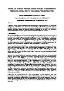
where m are the eigenvalues of the Z il ( n) , Q is the number of distinct eigenvalues, cm are the phase velocities of the elastic waves and k m are the corresponding wave numbers. The domains of integration for the dynamic and static parts of the fundamental solutions are defined as follows (figure 1):
dL d D S {0 2 }, dS n b, D R {0 b 1; 0 2 },
(15)
n b, 1 b2 d be, e r r , e e1 , e2 , e3 ,
(16)
d e2 cos e1e3 sin , e1 cos e2 e3 sin , 1 e32 sin
1 e32 .
(17)
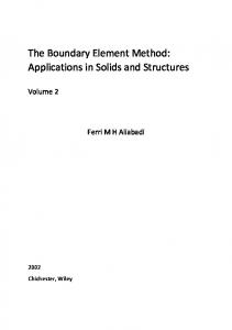
Figure 1. A schematic representation of vectors r, e, n and d involved in numerical evaluation of magneto-electro-elastic fundamental solutions. In this formulation the mixed boundary elements are employed for spatial discretization of equation (8). Boundary is discretized with quadratic quadrilateral elements. In order to correctly model continuous generalized displacements and discontinuous generalized tractions in each boundary element, linear and constant shape functions are used, respectively. For efficient numerical implementation of dynamic fundamental solutions the regular parts and their spatial derivatives are interpolated [14] over a boundary elements using the shape functions of five-node element (figure 2): N m 1 , 2
1 1 1(m )1 1 2(m )2 14 N 5 , N 5 1 , 2 1 12 1 22 , m 1, 4, (18) 4
where 1.0 1 , 2 1.0. Approximation takes place when a particular boundary element is located relatively far from the collocation point, i.e. when R / l k where R is the distance to the boundary element, l is the average side length of all boundary elements and k is a constant (see scheme at figure 3). We find that k 2.0 allows reducing the computation time by almost 50% while retaining the acceptable accuracy of the results. After enforcing the boundary conditions a standard collocation technique leads to a complex-valued system of linear algebraic equations: A k p k fk ,
(19)
where A k C N dof Ndof is the influence matrix, fk C1 Ndof , p k C Ndof 1 contain all the known and unknown boundary nodal values, respectively; Ndof is the total number of unknowns.
4
6thCICMCM IOP Conf. Series: Journal of Physics: Conf. Series 1234567890 919 (2017) 012021
IOP Publishing doi:10.1088/1742-6596/919/1/012021
Figure 2. Five-node element.
Figure 3. Fundamental solutions and their spatial derivatives are approximated over the boundary elements which are located at the shaded region. All variables in equation (19) correspond to the specific value of a Laplace transform parameter sk . In order to obtain a time domain solution we need to assemble and solve system (19) for a set of Laplace transform parameters. Once solutions on a complete set of Laplace transform parameters sk are obtained, we employ a numerical inversion routine to retrieve time domain solutions. 4. Convolution Quadrature Method for numerical inversion of Laplace transform With the Convolution Quadrature Method [16, 17] one can approximate a convolution integral t
f (t ) y (t ) g (t ) y (t ) g ( ) d ,
(20)
0
as follows n
f ( n t ) k ( y ) g ( k t ), n 1, N ,
(21)
k 1
where y is the Laplace transform of y (t ), t is the time step size and N is the total number of time steps so 0,T is the total time interval with T N t. Now let f ( s ) be the Laplace transform of f (t ) . Then,
f (t ) L1 f ( s) ,
(22)
where L1 denotes the inverse Laplace transform operator and s is the Laplace parameter. We introduce the following auxiliary functions F1 ( s ) sf ( s ), F2 ( s ) 1 s . By definition,
F1 (t ) L1 F1 ( s) , F2 (t ) L1 F2 ( s) .
5
(23)
6thCICMCM IOP Conf. Series: Journal of Physics: Conf. Series 1234567890 919 (2017) 012021
IOP Publishing doi:10.1088/1742-6596/919/1/012021
The transformed function f ( s ) can be rewritten as f ( s ) F1 ( s ) F2 ( s ).
(24)
f (t ) L1 f ( s ) L1 F1 ( s) F2 ( s ) F1 (t ) F2 (t ).
(25)
Therefore, we have
We notice that F2 (t ) H (t ), where H (t ) is the Heaviside function defined by
t 0 H (t ) 1, 0, otherwise.
(26)
Now we apply the CQM with the Backward Differential Formula of order two [15, 18] as an underlying multi-step method, to numerically approximate the convolution integral in equation (25) and thus obtain f (t ) : n
n
f (0) 0, f ( n t ) k ( F1 ) H ( k t ) k ( F1 ), n 1, N , k 1
k ( F1 )
Rk 2
sp
2
0
F1 s p e ik d
(27)
k 1
Rk L
L 1
F1 s p e p 0
ik p
R k L
L 1
s f s e p
p
ik p
,
(28)
p0
(z p ) i p , z p Rе p , p 2 L , ( z p ) 3 2 2 z p z 2p 2, t
(29)
where the L-point trapezoidal rule with equal steps 2 L for numerical evaluation of the weights k , 0 R 1 is a CQM parameter. 5. Numerical examples Consider a magneto-electro-elastic cube with an edge length of 1 m. At the bottom face x3 0 m the following boundary conditions are prescribed: u1 0, u2 0, u3 0, 0, 0; at the upper face x3 1 m the cube is subjected to uniaxial and uniform impact loading t3 t3* H (t ), t3* 100 Pa with H (t ) being the Heaviside function. Two cases are considered: when the cube is homogeneous and when it contains a central cubic cavity with the side length of 0.45 m (figure 4). The rest of the faces are traction free. The cube is made of BaTiO3-CoFe2O4 with density 5550 kg/m 3 and with the following effective material properties [19]: 0 0 0 213 113 113 0 0 0 113 213 113 0 0 0 0 0.15 0 0 0 0 GPa, e 0 0 0 0.15 0 0 C m2 , CE 113 113 207 0 0 0 49.9 0 0 0 0 0 2.71 2.71 8.86 0 0 0 0 49.9 0 0 0 0 0 0 50
0 0 0 0 0 185 0 0.24 0 ε 0 0.24 0 10 9 C V m , q 0 0 0 185 0 0 N A m , 0 6.37 0 0 0 222 222 292 0 0 0 0 -5.23 2.01 0 λ 0 -5.23 0 1012 N s V C, μ 0 2.01 0 104 N s2 C 2 . 0 2750 0 0.839 0 0
6
6thCICMCM IOP Conf. Series: Journal of Physics: Conf. Series 1234567890 919 (2017) 012021
IOP Publishing doi:10.1088/1742-6596/919/1/012021
The boundary element results for elastic displacements u3 ( t ), electric potential (t ) and magnetic potential (t ) at point A (0.5, 0.5, 1.0) m for the homogenous cube and at points A and B (0.5, 0.275, 0.5) m for the cube with a cavity are shown in figures 5-7 and figures 8-10, accordingly. In both cases three different uniform meshes with 216 (mesh 1), 384 (mesh 2), 600 (mesh 3) and 312 (mesh 1), 600 (mesh 2), 984 (mesh 3) elements were used, respectively. The results obtained with the proposed formulation indicate rapid convergence, even for magnetic potential behaviour.
Figure 4. Magneto-electro-elastic cube under impact loading. 10-9
0
displacements u3, m
-0.2 -0.4 -0.6 -0.8 -1 Mesh 1 Mesh 2 Mesh 3
-1.2 -1.4
0
0.2
0.4
0.6
time t, s
0.8
1 10-3
Figure 5. Displacements u3 t at point A.
Figure 6. Electric potential t at point A. 10-9
0.5
displacements u3, m
0 -0.5 -1 Mesh 1, pt. Mesh 2, pt. Mesh 3, pt. Mesh 1, pt. Mesh 2, pt. Mesh 3, pt.
-1.5 -2 -2.5
0
0.2
0.4
0.6
time t, s
Figure 7. Magnetic potential t at point A.
0.8
A A A B B B
1 10-3
Figure 8. Displacements u3 t at pts. A, B.
7
6thCICMCM IOP Conf. Series: Journal of Physics: Conf. Series 1234567890 919 (2017) 012021
Figure 9. Electric potential t at pts. A, B.
IOP Publishing doi:10.1088/1742-6596/919/1/012021
Figure 10. Magnetic potential t at pts. A, B.
In the second example a magneto-electro-elastic solid with more complex shape and loading conditions is considered (figure 11). As in the previous example, two cases are examined: when the solid is homogeneous and when a rectangular prismatic cavity is present. The dimensions of the cavity are 0.03 0.03 0.08 m and the coordinates of its center are (0.025, 0.025, 0.05) m. On the top half of the left face x1 0.0 m of the solid the tractions t1 t1 H (t ), t1 100 Pa are applied and on the bottom face x3 0 m the following boundary conditions are prescribed: u1 0, u2 0, u3 0, 0, 0. The rest of the faces are traction free. The material is again BaTiO3-CoFe2O4 with properties defined in the previous example. In figures 12-14 obtained results for the displacements u1 t , electric potential t and magnetic potential t at the point A (0.1, 0, 0.1) m for both cases (with and without cavity) are displayed. As it can be observed, the proposed boundary element approach yields stable results for this considerably complex problem.
Figure 11. Magneto-electro-elastic solid with complex shape and loading conditions. 6. Conclusions In this paper we have presented a Laplace domain direct boundary element formulation for transient dynamic problems of three-dimensional linear magneto-electro-elasticity. The Laplace transformed generalized fundamental solution is represented as a sum of singular and regular parts. The dynamic part is expressed as a surface integral over a half of a unit sphere and the singular static part as an integral over a unit circumference. The boundary elements are selected in a way that allows simultaneous modeling of continuous generalized displacements and discontinuous generalized
8
6thCICMCM IOP Conf. Series: Journal of Physics: Conf. Series 1234567890 919 (2017) 012021
IOP Publishing doi:10.1088/1742-6596/919/1/012021
tractions. The spatial discretization is done by a classical collocation scheme. Time domain solutions are retrieved via Convolution Quadrature Method for numerical inversion of Laplace transform. To verify the proposed formulation, a simple numerical example of a magneto electro-elastic cube under uniform uniaxial impact loading is presented. Additionally, the ability to produce stable numerical results was demonstrated on a problem involving a solid with complex shape and under sophisticated magneto-electro-mechanical loading.
Figure 12. Displacements u1 t at point A.
Figure 13. Electric potential t at point A.
Figure 14. Magnetic potential t at point A. Acknowledgments The reported study was funded by the Russian Foundation for Basic Research, according to the research project No. 16-38-60097 mol_a_dk. References [1] Milazzo A and Orlando C 2012 Compos. Struct. 94 3710-21 [2] Zhu X, Huang Z, Jiang A and Chen W Q 2010 Eng. Anal. Bound. Elem. 34 927-933 [3] Milazzo A, Orlando C and Alaimo A 2009 Smart Mater. Struct. 18 085012 [4] Daga A, Ganesan N and Shankar K 2009 Int. J. Comput. Methods Eng. Sci. Mech. 10 173-185 [5] Daga A, Ganesan N and Shankar K 2009 J. Intel. Mat. Syst. Str. 20 1203-20 [6] Li X C and Yao W A 2006 Eng. Anal. Bound. Elem. 30 709-717 [7] Ding H, Jiang A, Hou P and Chen W 2005 Eng. Anal. Bound. Elem. 29 551-561 [8] Haojiang D and Aimin J 2004 Compos. Struct. 82 1599-1607 [9] Heyliger P R and Pan E 2004 AIAA J. 42 1435-43
9
6thCICMCM IOP Conf. Series: Journal of Physics: Conf. Series 1234567890 919 (2017) 012021
[10] [11] [12] [13] [14] [15]
[16] [17] [18] [19]
IOP Publishing doi:10.1088/1742-6596/919/1/012021
Pan E and Heyliger P R 2003 Int. J. Solids Struct. 40 6859-76 Buroni F C and Saez A 2010 P. R. Soc. A 466 515-537 Pan E 2002 Z Angew. Math. Phys. 53 815-838 Rojas-Díaz R, Sáez A, García-Sánchez F and Zhang Ch Int. J. Solids Struct. 45 144-158 Matsumoto T, Tanaka M and Ogawa Y 2003 Proc. of Second MIT Conference on Computational Fluid and Solid Mechanics vol 2 (Oxford: Elsevier Science Ltd) pp 2071-73 Igumnov L A, Litvinchuk S Yu, Petrov A N and Ipatov A A 2016 Numerically analytical modeling the dynamics of a prismatic body of two- and three-component materials Advanced Materials: Manufacturing, Physics, Mechanics and Applications (Springer Proceedings in Physics vol 175) ed I A Parinov et al (Cham: Springer International Publishing) chapter 35 pp 505–514 Lubich C 1988 Numer. Math. 52 129-145 Lubich C 1988 Numer. Math. 52 413-425 Schanz M 2001 Wave Propagation in Viscoelastic and Poroelastic Continua: A Boundary Element Approach (Springer-Verlag Berlin Heidelberg) Xue C X and Pan E 2013 Int. J. Eng. Sci. 62 48-55
10