such as PeopleSoft⢠has not been widely articulated. .... Mapping documents for many target system tables had been produced, however, these were merely ...
The BRIDGE: A Toolkit Approach to Reverse Engineering System Metadata in Support of Migration to Enterprise Software By Juanita Walton Billings (1) (1) Information Systems Research Institute Virginia Commonwealth University Richmond, Virginia
Lynda Hodgson (2)
Peter Aiken (1) (2)
School of Business and Economics Longwood College Farmville, Virginia
Abstract The role of reverse engineering system metadata when migrating legacy systems to enterprise software such as PeopleSoft has not been widely articulated. Bridging the gap between new enterprisewide software systems and legacy systems has proven to be an enormous and costly hurdle when attempted without sufficient understanding of the legacy environment and enterprise metadata. We present a model-based methodology for constructing a metadata-based foundation for migrating data from legacy systems to enterprise software. The methodology components include: • • •
analysis of project organization, constraints and definition, development of project control structure, and deployment of toolkit components to capture, analyze and utilize metadata.
Methodologies work best when supported by appropriate tools. Based on widely available Office-suite components, a flexible toolkit was developed to support the methodology and facilitate system evolution. The toolkit allows users to capture, analyze, and publish various implementation-specific metadata. The toolkit publishes metadata for use by the technical implementation team as well as by project management and business users. We describe each methodology component, the associated toolkit elements developed to implement each component, the various component outputs, and the resources required to implement the solution. The methodology was developed in the context of an anonymous real world implementation. Organizations can use this approach to create a sound basis for reverse engineering system metadata when migrating to enterprise software.
Introduction The migration to enterprise software packages is a gargantuan, convoluted, and very expensive task for any organization. According to one widely quoted report, in a typical year three-quarters of all IT projects will either overrun or fail, resulting in almost $100 billion in unexpected costs [1]. This research focused on the development of a toolkit methodology for use during a large-scale legacy migration effort. An interactive, simple, userfriendly toolkit was designed to provide a point-and-click environment for use by technical developers and business users during migration efforts, as well as templates for use during evolutionary phases. Hoping to quickly access system metadata and aid management while providing key facts vital to the migration effort which describe the organization's legacy and target environments, the toolkit design provides a basis for communication between conversion project manpower. The toolkit contains multiple complementary components designed to capture, associate, connect, and manage legacy and target system metadata during reverse engineering [2 & 3] of system metadata, making it possible to track sources and uses of data.[4] The toolkit also supports problem identification, isolation and resolution and provides conversion issues tracking and other project details. In addition to assisting with target system application management, it provides on-line support for identifying, researching, and providing formal associations between metadata describing: • • • • • •
custom and native target system fields, files and associated properties; legacy system fields, files and properties; associations among and between target and legacy system fields, files and properties; design specifications associated with customized elements in the target system; migration mappings between legacy and target system data items; and business process constraints.
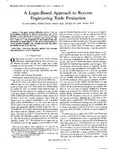
The conceptual toolkit mapping capabilities are illustrated in Fig. 1. The integration of catalogued legacy/target system technical and project management metadata into a comprehensive repository supports effective and efficient control of system evolution, offering savings opportunities in terms of efficiencies realized, timely problem resolution and system documentation and maintenance. The straightforward design encourages and facilitates user investment. In addition, the toolkit design was conceived as evolving into a catalogued cross-reference of information resources and becoming an essential foundation for its corporate data repository.
•Metadata (Legacy and Target Systems Fields, Files, Properties and Associations)
Metadata Reporting Design Specifications Tracking
The BRIDGE
Subsystems Tracking Migrations Tracking Application Management Support Issues Tracking
The BRIDGE Home Page
Fig. 1.
Notional toolkit mapping capabilities.
Step 1: Analysis of Project Organization, Constraints and Definition Project Organization Implementation Philosophy. The history of the project and the size of the organization made it important to consider prevailing attitudes of management concerning system architecture [5]. Corporate structure was being analyzed and realigned to include responsibility for enterprise development with the planned hiring of a system architect. Functional responsibilities of this position focus primarily on the dynamic system organization which interconnects the money, manpower, materiels, and MIS that characterize every organization. Evidencing a history of strong support for its operations via vigorous information systems services, the firm maintains a large, centralized MIS department. The sponsoring organization, a national retail product reseller, committed to transition from an AS400/Software 2000 environment to a UNIX-based PeopleSoft environment as a replacement for 27 homegrown HR and pay-related systems. Middle management staff were added or shifted from other projects; technical resources were transferred or hired; functional users were assigned responsibility for defining requirements, identifying legacy data elements and processes, and verifying results. Project planning and budgeting functions were conducted resulting in estimated development time and cost. These were notably understated. The tedious task of evaluating existing business processes as they related to the business rules logic of the target system began. Because many were not inherent in the target system, the not unusual decision was made to customize the target system. Customization included 708 custom tables and 2,359 custom fields. Project Constraints Pertinent employee legacy data resided on an AS400 server running Software 2000 with multiple libraries, tables, fields, and processes to accommodate a workforce of over 100,000. Other relevant data was maintained on other AS400 servers, UNIX servers running Sybase, Informix, Allbase, Image, Oracle, and proprietary database applications to manage specific business processes. For example, one legacy custom application was in place to process data from hundreds of outlying locations and transmit it to centralized storage for processing and reporting. Predictably, quality of both the legacy data [6] and the legacy metadata [7] was too often inadequate, e.g., field element content descriptions were inaccurate; data was missing or incorrect. Conversion project documentation was often inadequate and lacking in version control. Moreover, legacy-side technical expertise was already thinly spread and project HR experienced a high turnover during the migration process. These factors motivated an increase in the use of outside consultants. The pervasive use of consultants and needed rework of fit-gap analyses—to accommodate subsequent release versions (from 5.0 to 7.5, incrementally), data migration mappings, and system requirements had multiple impacts on the conversion: project cost overruns, unmet development deadlines, the complexity of optimally coor-
dinating skill levels and experience. The conversion team relied on ad hoc database applications, spreadsheets and text documents to document the system and migration process. Overall project progress was monitored with off-the-shelf project management software. During Year Two of the project, it became clear that the largest obstacle was an inability to reliably track legacy metadata and effectively control scope creep. An available toolkit was identified, but the base price tag, $85,000.00, represented major cost overrun to an already out-of-budget project—especially in terms of changes required to reflect site customizations. Nor was it compatible with the CASE tool chosen by the firm for longterm data modeling and object management. In light of this, the organization opted to design its own methodology and toolkit to support the conversion effort. CONVERSION JIGSAW PUZZLE
Project Definition Development of Project Control Structure. The toolkit development team used a four-component process to better understand and address conversion team needs. Consequently, opportunities were identified for improved efficiency and effectiveness by creating a conversion model incorporating all high-level management and production requirements, illustrated in Fig. 2.
Analytical, Design, Modeling and Mapping Devices
Issues Identification and Resolution, System Support, Scheduling
Naming Conventions Version Control Migration Order Documentation Hardware/Software Compatibilities
Requirements Integration
Fig. 2. Migration Project Control Issues
Component 1
Formal/informal interviews with business and technical staff and consulting experts to identify and model order of procedure for migration.
Component 2
Identification of in-house tools for tracking and documenting evolution, with emphasis on retaining, realigning or redesigning for future use.
Component 3
Analysis, design (or redesign) and integration of various tools (such as databases, spreadsheets, templates, etc.) to be used throughout evolution.
Component 4
Development of trouble-shooting and problem resolution tools to be used once installation of target system component was accomplished and end users began interacting with the new environment.
This methodology produced the framework of the toolkit, providing tracking capabilities and making possible point-and-click navigation through data mapping information, data source information and data use information, providing answers to many conversion-specific questions. See, The BRIDGE - Metadata Directory, below. Step 2: Formulating the Control Structure. Determining the precise steps through which conversion advances led to development of the on-line structure required to plan, organize, direct and control the project and, further, capture current and appropriate state-of-the-system for use by a variety of users: production (analysis, design, construction, migration and implementation), support (life cycle maintenance), functional (business process) and technical (infrastructure). By linking these aspects, project management enforces standards and version control while ensuring the most accurate environment in which to make project decisions. It is important, here, to critique the value of operating system functionality. In a Windows-based environment, it is essential that the “linking” functionality be employed to enforce version control by strict CRUD access to project documentation. The BRIDGE control structure is based on the order of events in the accomplishment of a system evolution: (1) concept, (2) analysis, (3) design, (4) construction, (5) migration, (6) implementation, and (7)support. It further reflects system constraints inherent to any system evolution: (1) management, (2) infrastructure, and (3) special issues (such as Y2K compliance). In addition to the very precise directory structure, The BRIDGE provides templates and links to documents intended to capture essential project information and
produce project deliverables: high-level design, fit-gap analysis, general design, conceptual design, functional design specification, and technical design specification documents. Other documentation is also available. Step 3: Deployment of Toolkit Components to Capture, Analyze and Utilize Metadata A two-member team of students from Virginia Commonwealth University, Information Systems Research Institute (ISRI) was tasked with producing a target system data model and toolkit to report data source tracking, data use tracking and metadata for data mappings. What follows is a report of the development of The BRIDGE, including summaries of legacy and target system metadata capture, development of the PeopleSoft data model, and design of data source tracking and data use tracking functions. Task: Reverse Engineering for System Evolution Employing generally accepted reverse engineering techniques, the development team set out to accomplish the following steps. 1. 2. 3. 4. 5. 6. 7. 8. 9. 10. 11.
Identify legacy libraries and files of data elements to be migrated. Identify use and "owner" of each. Identify need for any modification to each. Identify legacy processes utilizing each legacy file/field. Identify dependent legacy and target processes and outputs utilizing each. Identify functional owner of each legacy process. Identify functional user of each legacy output. Extract and load legacy metadata to The BRIDGE. Extract and load target system metadata to The BRIDGE. Create data mappings and associations. Publish reports as required.
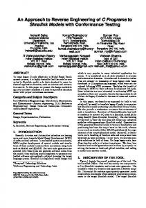
Reverse Engineering Issues. Legacy metadata was extracted from numerous locations, with varying degrees of automated support available. Early issues regarding application-level protocol interconnectivity were addressed and resolved. Given the pervasive use of Microsoft products, the decision was made to implement using off-theshelf Office-suite components. Additionally, the integrated suite offered: (1) an ability to migrate to Informix; (2) the ability to publish toolkit elements in HTML or to a Lotus Notes database; (3) user-friendly design and testing features; (4) importing and exporting capabilities; and (5) no additional procurement cost. Mapping documents for many target system tables had been produced, however, these were merely MS Excel spreadsheet templates requiring manual input of target system information and associated legacy sources to document relationships. They were produced by a complex process of requesting a PeopleSoft record definition on-line, printing it, then re-keying it into Excel spreadsheets. Token effort was made at version control and naming conventions, but these quickly became inadequate. To speed up the process and provide valid decisionmaking information, metadata for both target and legacy systems was imported to The BRIDGE to permit cross-system element mapping. Target System Metadata Analysis Target system metadata was contained in tables within the DBMS. Tools were available to query all file names and descriptions [8]. Query results were published in Excel format and analyzed to categorize the types and functions of records. In addition to basic metadata tables, various cross-reference, process, report, and other tables became vital metadata sources for creating the target system metadata model. A list of the 253 PeopleSoft Version 7 site metadata tables is shown in Fig. 3.
PRCSDEFN PSACTIVITYDEL PSACTIVITYMAP PSAEAPPLDEFN PSAEAPPLTMP PSAESECTDEFN PSAESTMTADJDEFN PSAESTMTTMP PSAUTHITEM PSAUTHSIGNON_VW PSBUSCOMPREC PSBUSPROCDES PSBUSPROCSEC PSCHGCTLHIST PSCOLORDEL PSDDLDEFPARMS PSEVENTROUTE PSFMTITEM PSHOMEPAGEDEFN PSHOMEPAGEOPR PSHOMEPAGEXREF PSIMPFIELD PSLOCK PSMAPRECFIELD PSMENUDEFNLANG PSMSGAGTDEFN PSNVSBOOKREQUST PSOPRALIASTYPE PSOPRDEFN_INTFC PSOPTIONS PSPCMPROGDEL PSPNLFIELD PSPNLGROUPLANG PSPRCSLOCK PSPRCSRUNCDEL PSPROJECTDEFN PSQRYBIND PSQRYDEFN_VW PSQRYEXPR_VW PSQRYLINK PSRECDDLPARM PSRECDEL PSRECURDEFNLANG PSROLEQRY_VW PSSTATISTICS PSSTYLEDEL PSTOOLBARDEL PSTREECTRL PSTREELEAF PSTREESELECT01 PSTREESELECT05 PSTREESELECT09 PSTREESELECT13 PSTREESELECT17 PSTREESELECT21 PSTREESELECT25 PSTREESELECT29 PSTREESTRDEL PSX_HELPCONTEXT PSX_TREELEAF PSXFERITEM
PRCSDEFNGRP PSACTIVITYDES PSACTIVITYTXT PSAEAPPLDEL PSAEOPTIONS PSAESECTTMP PSAESTMTADJTMP PSAPPSTBLVER PSAUTHITEM_VW PSBUSCOMPDEFN PSBUSPROCDEFN PSBUSPROCDESLG PSBUSPROCTXT PSCHGCTLLOCK PSDBFIELD PSDDLMODEL PSEVENTRTLANG PSHOLIDAYDEFN PSHOMEPAGEDEL PSHOMEPAGESEC PSIDXDDLPARM PSIMPXLAT PSMAPEXPR PSMAPROLEBIND PSMENUDEL PSMSGAGTLANG PSOBJCHNG PSOPRCLS PSOPRDEFN_TEMP PSPCMNAME PSPNLDEFN PSPNLFIELD_VW PSPNLGRPDEFN PSPRCSPRFL PSPRCSRUNCNTL PSPROJECTDEL PSQRYCRITA_VW PSQRYDEFNLANG PSQRYFIELD PSQRYRECORD PSRECDEFN PSRECFIELD PSRECURDEL PSROLEUSER PSSTEPDEFN PST_PNLFIELDS PSTOOLBARITEM PSTREEDEFN PSTREELEVEL PSTREESELECT02 PSTREESELECT06 PSTREESELECT10 PSTREESELECT14 PSTREESELECT18 PSTREESELECT22 PSTREESELECT26 PSTREESELECT30 PSVIEWTEXT PSX_TREE_SAVE PSX_TREELEVEL
PSACCESSPRFL PSACTIVITYDESLG PSACTIVITYTXTLG PSAEAPPLSTATE PSAEREQUEST PSAESTEPDEFN PSAESTMTDEFN PSASOFDATE PSAUTHPRCS PSBUSCOMPDEL PSBUSPROCDEFNVW PSBUSPROCLANG PSBUSPROCTXTLG PSCLOCK PSDBFIELD_VW PSEVENTDEFN PSFMTDEFN PSHOLIDAYDEL PSHOMEPAGELANG PSHOMEPAGETXT PSIMPDEFN PSINDEXDEFN PSMAPFIELD PSMAPROLENAME PSMENUITEM PSNVSBOOK PSOBJGROUP PSOPRCLS_TEMP PSOPRDEFN_VW PSPCMNAME_VW PSPNLDEFN_VW PSPNLGDEFNLANG PSPNLGRPDEL PSPRCSRQST PSPROGNAME PSPROJECTITEM PSQRYCRITERIA PSQRYDEL PSQRYFIELD_VW PSQRYRECORD_VW PSRECDEFN_VW PSRECFIELD_VW PSRELEASE PSSERVERSTAT PSSTEPLANG PSTBARITEMLANG PSTREEBRADEL PSTREEDEFNLANG PSTREENODE PSTREESELECT03 PSTREESELECT07 PSTREESELECT11 PSTREESELECT15 PSTREESELECT19 PSTREESELECT23 PSTREESELECT27 PSTREESELNUM PSWLINSTMAX PSX_TREEBRANCH PSX_TREENODE
PSACTIVITYDEFN PSACTIVITYLANG PSACTIVITYXREF PSAEAPPLSTMP PSAEREQUESTPARM PSAESTEPTMP PSAESTMTDEFNADJ PSAUDIT PSAUTHSIGNON PSBUSCOMPLANG PSBUSPROCDEL PSBUSPROCMAP PSBUSPROCXREF PSCOLORDEFN PSDBFIELDLANG PSEVENTLANG PSFMTDEL PSHOMEPAGE_VW PSHOMEPAGEMAP PSHOMEPAGETXTLG PSIMPDEL PSKEYDEFN PSMAPLEVEL PSMENUDEFN PSMENUITEMLANG PSNVSBOOKLANG PSOPRALIAS PSOPRDEFN PSOPROBJ PSPCMPROG PSPNLDEL PSPNLGROUP PSPNLTREECTRL PSPRCSRQSTXFER PSPROGNAME_VW PSPROJECTMSG PSQRYDEFN PSQRYEXPR PSQRYHEADLANG PSQRYSELECT PSRECDEFNLANG PSRECURDEFN PSROLEDEFN PSSPCDDLPARM PSSTYLEDEFN PSTOOLBARDEFN PSTREEBRANCH PSTREEDEL PSTREESELCTL PSTREESELECT04 PSTREESELECT08 PSTREESELECT12 PSTREESELECT16 PSTREESELECT20 PSTREESELECT24 PSTREESELECT28 PSTREESTRCT PSWORKLIST PSX_TREEDEFNLNG PSX_TREENODENUM
Fig. 3. Enterprise Software Metadata Tables Listing
Relying in part on previous research (see [9 & 10]), the identified metadata files were categorized, ranked, and published to Excel for import to Access following analysis. Analysis provided a traceable route through the target system. The team created a data commonality analysis by listing all metadata files and their elements and cross-referencing duplicates or pseudonyms. Associating common elements among the files, the team was able to construct a sequence logic to track the internal target system functioning. Applying the sequence logic, the
team, using target system metadata, could precisely track the route of each field through the target system as it interacts with all activities and events occurring within the target application (Fig. 4). PSHomePage
PeopleSoft™ 7.01 Element Routing
PSHOMEPAGEXREF ComponentName PSBUSPROCXREF BusProcName
PSBusProcName
BusProcName
PSWorkList
WorkListName
ComponentName PSACTIVITYXREF
BusProcName
ActivityName(1)
PSMenuDefn
PSStepDefn
MenuGroup
MenuName(2)(3) BarName(2) ItemName(2)(3)
PSMenuItem
EventNamee
StepName
PSMsgAgtDefn
PanelItemName
EventName(1)
MenuName
ProgramName BarName
PnlGrpName(3)
ItemName
PSPnlGroup
PanelName
PSPnlField
RecName
PSDBField
FieldName
RecName
PSEventDefn
RouteName
PSEventRoute
XREF_MENU_VW
PSRecField
EVENT
ACTIVITY Fig. 4. PeopleSoft v. 7.01 Metadata for Element Routing (Data Uses)
By isolating any given target system field, its properties and associations with events (e.g., notifying Benefits personnel of new hires) and activities (e.g., as computing benefits packages statistics) can be determined. Based on the logic established, a target system data metadata model was created (Fig. 5).
Interface Data Panel
Input
Homepage Business Process
Field
Menugroup
(Parent/Child)
Menuname
Record
Menuitem
Menubar
Activity
Output
Management Reporting
Step Intranet connection
Fig. 5. Target System Data MetaModel
Event Message Agent
Processing
Legacy System Metadata Analysis Legacy system metadata was far more complex. This phase focused initially on seemingly well-structured legacy data managed by Software 2000 (S2K), narrowing the analysis focus and providing a legacy data subset to model. Legacy system analysis also focused on an interconnected hardware and software system of proprietary and modified off-the-shelf applications used to collect, manage, and report corporate data. To correctly "address" any given element within S2K, the following locations must be known: (1) the server on which the DBMS is employed, (2) the database segments that exist, (3) the files within those segments, and (4) the elements of those files. Using these facts and creating a unique database identification number based on the server and DBMS designations, each element can be tracked forward or backward to database segments, files and fields (Fig. 6).
Enterprise Metadata
Environment Modifications F I L E S
(PSoft) Field
Field ID#
(New) Field
KEY=
(Old) Field
DB ID# + Segment ID# + File ID# + Field ID#
D A T A B A S E S E G M E N T S
D A T A B A S E M G T
S E R V E R S
S Y S T E M S
Legacy Environment
Fig. 6. Enterprise Metadata Model
S2K utilities produce hard copy system metadata reports, but not soft copies that can be manipulated to extract the relevant metadata such as field name, field length, field attribute and field descriptions. Informix scripts were written to extract the S2K metadata to migrate the data to Excel in preparation for import to The BRIDGE. Task: Design and Develop Toolkit Components The BRIDGE was designed to assist in the implementation of enterprisewide applications based on metadata describing systems environments. Obviously of interest to project management is the resultant reduction to costs associated with error and inefficiency. By maintaining a centralized and secure repository, keying errors, misspellings, guesswork, and, in general, "information deficiency" can be virtually eliminated. Toolkit components designed to avoid these costly errors are illustrated in Fig. 7 below. Design of the toolkit hinged on several basic components: (1) identification of the migration process steps; (2) identification and analysis of state-of-the-system migration methodologies in place at each stage, e.g., analysis of legacy metadata, correlation to target system metadata, data capture/load, issues management, process run control, roll-out, clean-up and documentation; (3) integration of heterogeneous legacy environment metadata into a seamless whole to avoid redundancy, implement version control, security, etc.; and (4) need for user interfaces to streamline future target system management and support. As expected, many opportunities were identified for production of standards, procedures, conversion-specific tools and generally improved organization of the project deliverables. The expected result was better communication among technical and business migration
team members, fewer instances of error, diminished demands on systems resources, fewer reworks, and ultimately a smoother overall conversion process. *The BRIDGE: System Evolution Management Toolkit Based on analysis of elements basic to any system evolution and on the reverse engineering methodology employed, tools were designed to assist cross-functionally with the implementation of an enterprisewide software package. What follows is a brief description of each database tool.
The BRIDGE System Metadata directory
Design Specifications directory
Business Processes directory
Migrations directory
Load Run Control directory Conversion Issues directory
Patch Activity directory
System Documentation templates Fig. 7. The BRIDGE - Conversion Project Database Tools
The BRIDGE - Data Geography: Tables were created in The BRIDGE to accommodate the "key" that "opens" each data element "address." Assigning a unique key to (1) each database/server combination, (2) each segment of each database/server combination, (3) each file from each segment, and (4) each data element of each file allows users to locate elements and related metadata, identify the source of converted data, and associate element use with legacy processes. The BRIDGE guides users through three areas most likely to require support: (a) metadata issues, (b) data sources, and (c) data uses. The main menu narrows search categories to primary target system elements: fields, records, panels, menus, views and reports. Users can access information regarding the properties and sources and uses of those elements. The BRIDGE - Metadata Directory: From random sampling of testing incidents recorded by the testing team, The BRIDGE was designed to lead users to answers to questions such as the following. • • •
What custom/native fields and files exist within the legacy system and the target system, and what re their properties (name, type, length, format, etc.)? What target system structures, processes and reports are associated with a particular field and/or file? What technical design specifications are associated with custom elements of the target system?
• • •
What legacy element, or combinations, constitute the target system elements? What system processes require access to target system data? What legacy processes depend on target system data?
Fig. 8. Data Source Tracking
Because target system metadata is accessible in ODBC format, directly linking BRIDGE components to the target system permits metadata queries and provides real-time database-state reporting. The savings realized by eliminating the need to routinely refresh The BRIDGE offsets performance limitations. Since "data" truly is the combination of a fact and a meaning, then metadata provides in particular format the "information and documentation that makes data sets understandable and shareable for users" [11]. In addition to metadata for each element, the user can quickly explore the relationships between any primary element and any other primary elements. The BRIDGE - Data Mapper: The screen shown in Fig. 9 illustrates one of the most important toolkit functions. Data Mapper provides point-and-click functioning to identify any given data element, review its properties, match it with any underlying (converted) data element, and point it toward its new configuration. By restricting data "addresses" to one-to-one relationships between the four-element key, it is possible to establish any required many-to-one relationships between data elements by adding "NewFieldID#." This is especially useful when legacy data elements are combined to produce a single, target system data element. The information captured by Data Mapper leads to data source/use information. Providing the user with options for qualifying each evolving field, the conversion team has access to centralized critical information and documentation related to each field. In addition, Data Mapper provides a tool for tracking issues regarding the conversion of legacy data to the new environment. It provides space for toolkit users to make notes, raise questions or log resolutions regarding specific fields. Also included with this screen is a field to accommodate a direct link to technical specification documentation for individual target system elements. Finally, Data Mapper is designed to open the data map for modification as necessary, date-stamping and modifying the status of the earlier version, then creating an additional row in The BRIDGE table, Data Source
Tracking. As this function is employed, it captures a modification date so that system maintenance can purge unneeded information as indicated. Of course, updating migration issues relative to modification provides additional valuable information about relationships between legacy and target environments.
Fig. 9. Data Mapper
The BRIDGE - Migration Rules Directory: This function, a subscreen of Data Mapper, allows the developer to capture psuedocode (or even code language) for legacy data extraction, rebuilding, and loading if no ETL is employed. The Migration Rules Directory can contain code which, when queried, reports in text format that can be utilized in writing future extract procedures if needed. The BRIDGE - Migrations Tracking: The migrations tracking database provides for the capture of migration, and re-migration, activity information by specification identifier, as well as sign-off tracking necessary to manage the migration process. The BRIDGE - Business Process Tracking: Information about each business process—identifiers, process steps, dependencies, contacts, data inputs, outputs, and testing information such as test script identifiers, break points and recovery steps—is contained in a separate database (see Fig. 10). This tool permits the tracking of subsystem information, including business processes, interfaces, production applications, support applications, and implementation-specific details. The BRIDGE- Design Specification Tracking: Via its Tech Specs Link, The BRIDGE provides a hyperlink connection to text documents containing design and functional requirements and other pertinent information about the specification. The information in this table originated as a spreadsheet to provide intermediate search capabilities during the migration project. By converting the spreadsheet to an Access table, users retain this capability while gaining the ability to access centralized information via link to the element composite. Tech Spec Link also provides summary information and linking for individual specifications via the main menu. The BRIDGE - Patch Activity Tracking: Formalized change management for required post-implementation modifications must be enforced. This is true not only of target system construction, but also of target system infrastructure management. Target system updates are electronically published weekly in text format by the vendor. A "Patches and Fixes" component was developed to load and track information about those updates. Capture of update information is primarily a manual operation involving the cutting and pasting of information provided by the software vendor. Utilizing Word and Excel to massage and reformat the electronically provided information, the “patches and fixes” data is imported to the appropriate database tool.
Fig. 10. Data Use Tracking
The BRIDGE - User Log: User Log is a transparent function that tracks number of users and search strings, qualifying each by primary element type researched. By adding date/time stamps, User Log provides the opportunity to track which elements present the most challenges, how the toolkit is being used, the frequency of use and efficiency of the tool. Results The toolkit prototype generated significant interest across the team. Although factors related to development of The BRIDGE surfaced as early as four months prior to initial design and development of the toolkit, the cost associated with design and development of the toolkit consisted of direct labor costs exclusively. The cost of the two-person development team, working approximately 20 hours per week each for a period of four months, was less than $20,000. The four-month project included analysis and design, and extraction and load of test and live metadata. Given the almost 50% and 100% overruns for implementation project cost and time respectively (totaling millions of dollars), the "price tag" represents a significant cost savings, assuming early deployment of the toolkit could have eliminated much of the subsequent rework. Having no "parallel" test case against which to measure actual savings prohibits projections of savings to be anticipated by other users of The BRIDGE methodology. Based solely on a comparison to the price of an application-specific support tool, The BRIDGE also represents a cost savings in terms of initial outlay. Conclusion Understanding the contents and uses of legacy data when evolving from a legacy system to a new environment and reverse engineering systems to identify and formally locate the facts and meanings of corporate data has other benefits as well [12]. For example, development of corporate data "minimarts" that ultimately contribute to corporate data warehouses becomes simpler and more straightforward. By formally "addressing" the locations and tracking metadata of the system, more useful decision-making information becomes available to teams predicting performance and controlling operations. When employed in conjunction with the implementation methodology discussed here, the migration effort will run more smoothly, be more efficient, and cost less.
References
1
[Standish 1999] The Standish Group Report: Migrate Headaches, 1995 http://www.standishgroup.com/chaos.html.
2
Bachman, C, "A CASE for Reverse Engineering" Datamation, 1988:49-56 Jul 1, 1988, v34n13.
3
Elliot Chikofski and James H. Cross II "Reverse Engineering and Design Recovery: A Taxonomy" IEEE Software January 1990 7(1):13-17.
4
Finkelstein, C. and P.H. Aiken, Building Corporate Portals Using XML". 1999, New York: McGraw-Hill. 394 pages (ISBN 0-07-913705-9).
5
Michael L. Brodie & Michael Stonebraker Migrating Legacy Systems: Gateways, Interfaces & The Incremental Approach Morgan Kaufmann Publishers, 1995
6
K. Laudon "Data quality and due process in large interorganizational record systems" Communications of the ACM, January 1986 29(19):4-11.
7
M. J. Freeman and P. J. Layzell "A meta-model of information systems to support reverse engineering" Information and Software Technology, May 1994 36(5):283-294.
8
Aiken, P. H., Ngwenyama, O. K., and Broome, L. "Reverse Engineering New Systems for Smooth Implementation" IEEE Software, March/April 1999 16(2):36-43.
9
Aiken, P.H., "Reverse engineering of data" IBM Systems Journal, 1998. 37(2): p. 246-269.
10 Aiken, P.H., Data Reverse Engineering: Slaying the Legacy Dragon. 1996, New York: McGraw-Hill. 394 pages (ISBN 0-07-000748-9). 11 ISO 11179:195-1996 Information Technology - Specification and Standardization of Data Elements. 12 Cook, Melissa, Building Enterprise Information Architectures: Reengineering Information Systems 1996, Englewood Cliff, NJ Prentice Hall ISBN: 0-13-440256-1