Mobile Phone Detector, Frequency jamming Feature, Buzzer,. RF spectrum. 1. ... In a brief history, it was discovered that the rapid proliferation of mobile phones ...
International Journal of Computer Applications (0975 – 8887) Volume 143 – No.1, June 2016
The Design and Implementation of a Mobile Phone Detector Device with a Frequency Jamming Feature Oke A. O.
Falohun A. S.
Adigun A. A.
Computer Science and Engineering Department Ladoke Akintola University of Technology, Ogbomoso, Oyo State, Nigeria. PMB 4000, Ogbomoso
Computer Science and Engineering Department Ladoke Akintola University of Technology, Ogbomoso, Oyo State, Nigeria. PMB 4000, Ogbomoso
Computer Science and Engineering Department Ladoke Akintola University of Technology, Ogbomoso, Oyo State, Nigeria. PMB 4000, Ogbomoso
ABSTRACT In The development of ways to reduce malpractices in examination centers in all educational institutions is an important area of research. One of the major problems discovered aiding malpractices has been the creation of mobile phones, which however is a good communication device but needs to be curtailed during examinations. In order to have a 100% assurance that no student can cheat with his or her mobile phone a mobile detector system with a frequency jamming feature was developed using mobile cell phone detection techniques of measuring a cell phone's electromagnetic properties, determining an identifiable signature, measuring the RF spectrum and meeting the jamming requirements.
General Terms Security, Jammer, MTN network, Airtel Network, Etisalat Network, Globacom Network.
Keywords Mobile Phone Detector, Frequency jamming Feature, Buzzer, RF spectrum
1. INTRODUCTION Examination malpractices have consistently remained a bane of Nigerian educational system. Most foreigners say that the academic certificates being issued to graduates in Nigeria are no more valuable than the pieces of paper on which they are printed (Nicholas, 2011). Examination malpractice is an illegal behavior by a candidate before, during or after the examination so that such can attain success easily and cheaply. Hence, the worth and standard of the examination is violated. Examination malpractice is a cankerworm that portends grave dangers for the nation. Examination malpractice has been carried out successfully in many ways, part of which is the bringing in of micro written notes, the use of storage devices and communication devices. Communication devices happen to be the most effective means of malpractices today in higher institutions of learning. In a brief history, it was discovered that the rapid proliferation of mobile phones at the beginning of the 21st century to near ubiquitous status eventually raised problems such as their potential use to invade privacy or contribute to rampant and egregious academic cheating. In addition, public backlash was growing against the intrusive disruption cell phones introduced in daily life. While older analog cell phones often suffered from chronically poor reception and could even be disconnected by simple interference such as high frequency
noise. Increasingly sophisticated digital phones have led to more elaborate counters (Mohan, 2008). Intelligent Mobile Phone devices are alternative to more expensive measures against denial of services by service providers. This work concentrates in designing a system that will detect the presence of mobile phone signals from an unauthorized user in restricted areas which will in turn trigger another device to restrict the user from service (Abdul, 2008). The mobile detector system with frequency jamming feature will be able to jam mobile phone frequency signal upon detection to prevent the transmitted signal from getting to the users cell phone. This mobile detector system with frequency jamming features can sense the presence of an activated mobile cell phone from a distance. So it can be used to prevent the use of mobile phones in examination halls, confidential rooms, etc. It is also useful for detecting the use of mobile phone for spying and unauthorized video transmission. Jamming devices overpower the cell phone by transmitting a signal on the same frequency and at a higher enough power that the two signals collide and cancel each other out. Cell phones are designed to add power if they experience low-level interference, so the jammer must recognize and match the power increase from the phone. Some cell phone jammers are made to look like actual phones. Others are brief cased size or larger. The usefulness of Mobile Detectors covers areas such as Churches/Mosques, university lecture rooms, libraries, hospitals, fuel pumps, meeting rooms, banking halls and other places where silence is appreciated. The frequency jammer which is being housed in a small metal/plastic box and quite inconspicuous can be mounted on a wall or a ceiling (Christian, 2012). Cell phones are a full-duplex device which means they use two separated frequencies, one for talking and one for listening simultaneously. Some jammers block only one of the frequencies used by cell phones, while some have the effect of blocking both. The phone is tricked into thinking there is no service because it can receive only one of the frequencies. Less complex devices block only one group of frequencies, while sophisticated jammers can block several types of networks at once to head off dual-mode or tri-mode phones that automatically switch among different network types to find an open signal. Some of the high end devices block all frequencies at once, and others can be tuned to specific frequencies. Cell phone Jammers are usually simple devices with typically only a switch to turn it on and off, a light to show that it is
15
International Journal of Computer Applications (0975 – 8887) Volume 143 – No.1, June 2016 operational and an external antenna to send the signal. If the jammer is more sophisticated, it might include controls to set the jamming for varied frequencies or strengths. Small GSM jammers are usually powered by batteries. Often, the batteries are even the same as cell phone batteries. Larger GSM jammers are electrically powered (Ahmed, 2006).
leg is connected). The bottom right row is connected to the long leg of the LED (Pin 8). The antenna is connected to Pin 2 of the IC. A black wire is connected between one leg of the battery and the bottom left of the board. A red wire is also connected between the second leg of the battery and the bottom right row of the board.
2. PRINCIPLE OF OPERATION 2.1 Mobile detector and Frequency Jammer system In this paper, the intelligent mobile detector system with frequency jamming features is designed to detect the RF signals from mobile phones. A detailed description of the design in form of a block diagram is given in Figure 1. The mobile detector and frequency jamming system is able to disable mobile phones in restricted area. The jamming system detects Global System for Mobile Communication (GSM) signals at 900MHz. The necessary components employed in the construction are a signal detector with a monopole antenna, capacitors, light led, transistors and the power supply unit. The monopole antenna is tuned to 900MHz. Once the RF antenna receives wireless signal after the circuit has been powered by a 9Volts dc battery, the detector amplifies the received signal which in turn triggers the buzzer with resultant flickering of the LED when signal is detected and the Jammer will be manually switched ON.
Figure 1: Mobile Detector with Frequency Jammer
2.2 The Detector Unit Figure 2 shows the circuit of the detector unit consisting of capacitors, diode, resistors and LM358. It can sense the presence of an activated incoming and outgoing mobile phone calls, SMS and video transmission, from a distance of 2.5m, even if the mobile detector is kept in silent mode. The IC chip LM358 is placed on board (horizontal orientation), the variable resistor is placed on the board; the pins on separate rows. The center pin of the variable resistor is connected to pin 6 of the IC, and top and bottom pins to the bottom rows of the board. The bottom two rows are where the battery will be connected. A capacitor is inserted between the middle and top pin of the variable resistor. Pin 4 of the IC is connected to the bottom left row. Several other locations will use this connection for ground (negative battery terminal). A 6.8mega-ohms resistor and a capacitor are connected between pin 3 and pin 4 of the IC (pin 4, connected to ground). A capacitor is connected between Pin 3 and Pin 2 of the IC. A 6.8mega-ohms resistor is connected between Pin 3 of the IC and bottom pin of the variable resistor. The bottom pin of the variable resistor was connected to the battery positive terminal. Another 6.8mega-ohms resistor was connected between Pin 1 and Pin 2 of the IC. „Pin 1 and Pin 5 of the IC are connected together. One leg of the 1kilo-ohms resistor is connected to Pin 7 of the IC and the other leg is connected to the row above Pin 8. The long leg of the LED is connected to Pin 8, and the short leg to the row above Pin 8 (the row where one of the 1kilo-ohms resistor‟s
Figure 2. Circuit diagram of the Detector Unit
2.3 The Frequency Jammer Unit Figure 3 shows the jammer circuit, which consists of three main important circuits when combined together: RF amplifier, Voltage controlled oscillator and Tuning circuit. So the transistor Q1, capacitors C4 & C5 and resistor R1 constitute the RF amplifier circuit. This amplifies the signal generated by the tuned circuit. The amplification signal is sent to the antenna through C6 capacitor. Capacitor C6 remove the DC and allow only the AC signal which is transmitted in the air. When the transistor Q1 is turned ON, the tuned circuits at the collector get turned ON. The tuned circuit consists of capacitor C1 and inductor L1. This tuned circuit acts as an oscillator with zero resistance. The oscillator or tuned circuit produces the very high frequency with minimum damping. Then both inductor and capacitor of tuned circuit oscillate at its resonating frequency and hence jam the mobile signals. It is very important to choose the frequency to block. Basically, the mobile jammer will transmit at the same frequency as the mobile signal frequency at the base station. This device was design to block the downlink transmission because the frequency required to be blocked is a Very High Frequency (VHF). In this case, the device uses GSM 900 to block the frequency in range from 935 to 960 MHz, DCS 1800 to block the frequency range from 1805 to 1880 MHz and IMT 2000 (known as 3G) to block the frequency range from 2100 to 2170MHz.
Figure 3: Circuit of a Jammer
16
International Journal of Computer Applications (0975 – 8887) Volume 143 – No.1, June 2016
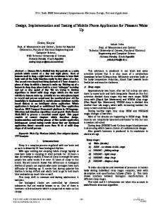
3. CONSTRUCTION AND TESTING 3.1 Construction and Testing Experiment was first carried out on a bread board then transferred to a printed circuit board. Figure 4 shows the components of the detector unit on bread board. Figure 5 shows the testing of the mobile detector without a jammer on bread board. The system was designed in three modules; the mobile detector unit, the jammer unit and the power supply unit. Designing the system in modules helps in easy troubleshooting. The system was tested against four mobile phone networks and against radio frequency receivers.
Figure 6: Connection on a PCB
3.3 Testing The design was tested with an active mobile phone. The moment the detector detects RF transmission signal from an activated mobile phone, it starts sounding a beep alarm and the LED blinks as shown in Figure 7 and then the jammer is switch on which automatically block all mobile network in that location. The alarm continues until the signal transmission ceases but will eventually stop once the jammer is switch on and all mobile networks are blocked. Figure 8 shows the mobile detector unit indication of the jammer and the detector system‟
Figure 4. Components of the Detector Unit on Bread Board
3.2 Construction on a Printed Circuit Board (PCB)
Based on the result and analysis, this mobile detector with frequency jammer can successfully detect and block the signal transmission of mobile phone and radio transmission. This device is tested with four main mobile operators in Nigeria and found to detect/jam these operators which are MTN, AIRTEL, ETISALAT and GLOBACOM when on 2G (EDGE), GSM and GPRS network.
A printed circuit board (PCB) is a self-contained module of interconnected electronic component found in devices from common beepers, or pagers, and radios to sophisticated radar and computer systems. The circuit is formed by a thin layer of conducting material deposited or printed on the surface of an insulating board known as the substrate. Individual electronic components are placed on the surface of the substrate and soldered to the interconnecting circuit as shown in Figure 6.
Light Indicator
Figure 7: The mobile detector unit indication when detecting a mobile phone signal
Figure 5. Testing Mobile Detector without a Jammer on Bread Board.
Figure 8: The mobile detector unit indication of the jammer and the detector system
17
International Journal of Computer Applications (0975 – 8887) Volume 143 – No.1, June 2016
4. RESULT AND ANALYSIS From the result of the test on the system it was discovered that the aim of this work was achieved.
4.1 Result The Mobile Detector with Frequency Jammer successfully detected and jammed all the four operators. Results obtained when the Mobile Detector with Frequency Jammer was ON and OFF for the four operators are shown in Figures 9 to 12. When the detector is ON it will detect the mobile phones in the range within 2G and GSM networks and once the jammer is switch on, it jams all networks in same range. The results show that this work functioned as intended.
A. Full AIRTEL Network
A. Full MTN Network
B. 10: No AIRTEL Figure A mobile Network phone before/after detection and jamming AIRTEL signal
B. Full MTN Network Figure 9: A mobile phone before/after detection and jamming MTN signal
A. Full ETISALAT Network
18
International Journal of Computer Applications (0975 – 8887) Volume 143 – No.1, June 2016
Figure 12: A mobile phone before/after detection and jamming GLOBACOM signal B. No ETISALAT Network Figure 11: A mobile phone before/after detection and jamming ETISALAT signal
5. ACKNOWLEDGMENTS Our thanks to the head of department, Computer Science and Engineering, Ladoke Akintola University of Technology Dr. Mrs. A. B. Adetunji for her encouragement in the course of this work. Yusuf is also appreciated for gathering information about this work. Our thanks also to Mr. Adeagbo for helping with the purchase of the equipment and all others whose names can not be mentioned. We say thank you all.
6. REFERENCES [1] Nicholas W. S. 2011, Study of Cellular Phone Detection Techniques , unpublished Thesis, Faculty of The Graduate College at the University of Nebraska [2] Mohan Kumar, D. 2008. “Mobile Bug”. Electronics for you magazine. www.espow.com/jammers/securitysurveillance [3] Abdul K.A, Asa‟d Nalm, Ahmed Hassan and Ayman Samier, 2008. Mobile phone intelligent jamming system. Jordan. A. Full GLOBACOM Network
[4] Christian C.M. 2012. "Design and Implementation of Intelligent Mobile Phone Detector". Academic Research International. Vol. 3, No. 1. [5] Ahmed, S.A., Ahmed N.R.M. 2006. Dual band mobile jammer for GSM900 and BSM1800.
IJCATM : www.ijcaonline.org
19