The bevel gears were designed to carry static, dynamic and maximum. 2 tangential tooth ... the idea of putting the sacks of cassava mesh in a box, and using a ...
Journal of A pplied Sciences Res earch, 5(10): 1285-1297, 2009 © 2009, INSInet Publication
The Design, Constrution and Testing of a Vertical Squeeze Cassava Pulp Dewatering Machine Olusegun, H.D. and Ajiboye, T.K. Department of Mechanical Engineering University of Ilorin, Ilorin Nigeria A bs tr ac t: Gari is a popular s taple food in Nigeria. It is got from the dry frying of dewatered c a s s a v a pulp. Cas s ava is a p la n t w h ic h o riginated from South A merica but is now grown in mos t of the A frican countries . The Nigeria n variety grows to a height of 0.6 to 2m. The root is the mos t us eful part of the plant. It is about 35cm in length with a d ia me t e r of about 10cm in the mid part of the root and tapers to the end of the root. The roots which are b ro w n are peeled. Ins tead of the local method of s tacking the pulp in s acks and puting heavy objects on top to dewater for two days , a motorized vert ic a l s q u e eze dewatering machine was des igned and fabricated to do the job of dewatering 200kg pulp in 33.72 minutes . This ma c h in e w as 7 times quicker than the IITA multi-purpos e pres s and 40 times quicker than the local method of dewatering. This was made pos s ible by de w a tering s crews working with a total torque of 1182K N mm, a maximum principal s tres s of 100N/mm2 , and a maximum s hear s tres s of 60N/mm 2 . T h e pulp platform were trans ported up and down by action of s crew followers . They operated with induced s heer s tre s s in t h e s crew and followers of 17.76 and 14.69N/mm2 which were adequately below the bearing pres s ure of 18N/mm 2 . T h e bevel gears were des igned to carry s tatic, dynamic and maximum tangential tooth load of 19.8, 1.07 and 9.05KN res pectively. The rapid rate of dewatering will e n h a n c e the production of gari and thus as s is t development. Key words : pulp, dewater toxic, s queeze, cyanide, grate. INTRODUCTION Cas s ava which is known biologically as “ manihot es culenta crantz” is a c ro p which has many varieties . It is als o known as manioc or yucca in s ome countries . The common variety s een in the s outhern part of Nigeria and at Ilo rin when fully grown do have height of between 0.6 to 2m. The root, which is the mos t us eful part of the c ro p is about 35cm in length. It has a diamet e r o f about 10cm at the mid part of the root, bu t t a p e r to about 4mm at the tail end of the root. Ca s s a va was firs t grown in South A merica where it was cultivated for over 5000 years before it was introduced to Nigeria by the Portugues e in the 17th Century. The c u lt ivation of the cas s ava crop is by the propagation of s tem cuttings . The crop take s a b o ut 9.12,18 o r 24 months to mature for harves ting depending on s pecies . The roots are dug up from the s o il, removed from the plant and was hed before being proces s ed, Pierres [5]. A b o u t 40% of A frican farmers grow cas s ava. The fres h root contains 50 to 75% of water, and les s than 1% protein. The remaining 99% is mos tly s tarch. The leave s and other parts contain a glyceride, linamarin from which hydrogen cyanide is releas ed by enzymic action Davids ons [6]. Hydrogen cyanide is toxic to
human health. The root is very us eful for indus trial and d omes tic applications . In the indus trial us e of cas s ava , detoxification of HCN takes place in the c h e mic al proces s es when s liced raw roots are s ometimes fermented for carbohydrates whic h are us ed for beer brewing and dis tillation. Cas s ava flour has found us eful application in the baking indus try. It is as indus trial s tarch, us ed for the production of gas oline and acetone. The dried cas s ava chips are proces s ed into animal feed, glues and manufacturing additive. A bout 60% of cas s ava is us ed today for indus tries a pplication and 40% for domes tic cons umption. T h e domes tic product of c a s s ava in W es t A frica cons is t of a fermented, s emi-dextrimized me al called gari .The cas s ava root is peeled, grate d into pulp or mes h, tied in s ack and allowed to ferment for a few days , then dewatered. The dewatered mes h is part ially gelatinized, dry fried s ometimes with palm oil to percentage drines s of about 12% and then milled . T h e gari is eaten as a pas te called eba with gravy, or s oaked in water and eaten with fis h, meat, groundnuts or “kulikuli”. Gari is a very popular meal becaus e of its relative cheap nes s when compared to other meals .This is becaus e cas s ava w ill grow on any type of s oil, and it does not require fertilizer.
Corresponding Author: Olusegun, H.D., Department of M echanical Engineering University of Ilorin, Ilorin Nigeria 1285
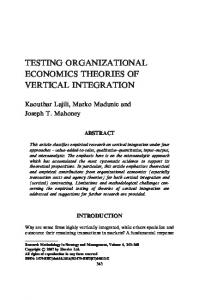
J. Appl. Sci. Res., 5(10): 1285-1297, 2009 A s far back as 1962, res earchers had ob s erved the need for a mechanical s ys tem of dewatering of cas s ava mes h in the gari proces s in g method. A kindele [1] obs erved the need for a neater mechanica l w a y of dewatering gari pulp to change the unhyg ie nic local method of water re mo v ed by compres s ing mes h s acks with heavy s t o n e s and metal objects . [8] He propos ed the idea of putting the s acks of cas s ava mes h in a box, a n d us ing a pulp compres s or to dewater all the mes h in the box. A s the box res tricted the outward flow of the water from the pulp, engineers introduced the open s crew pres s which proved s atis factory when c o mpared wit h t he other s ys tems , except for the cos t of manufacture and maintenance, A jibola [9 ] . In 1990 Eghareuvba clas s ified the s crew-type p re s s us ed for dewatering of cas s ava mes h into thos e where the mes h s acks are place on a platform and the top pre s s b a r is s c re wed to compres s the mes h s ack, and thos e that have the mes h s ac k on a platform which is s crewed upward to be comp re s s ed by a pres s bar that is s tationary at the t o p. The IITA put forward a double s crew pres s in 2007 which has a loading ca p a c it y of 200 to 350 kg applied to 5 bags per b a t c h o f cas s ava p u lp. The rate of dewatering is s uch that a pulp wit h initial mois ture content o f 70-80% is reduced to 4050% in 4hours . The motorized double s crew compres s ive travers e cas s ava pulp dewatering machine has a capacity of 200kg. T h e p u lp was reduced from 80% wetnes s to 25 % in 2hours . The machine is s hown on Figure 1. T he two power s crews 55mm diameter are the main fe atures of the double s crew ve rt ic al compres s ion cas s ava pulp dewatering machine. T he power s crews are threaded with acme thre a d s right ha n d e d at top half and made to be left handed at the bottom of the s crews . That way it w a s pos s ible to make the top a nd bottom platforms to move vertically towards each other in compres s ion Figure 2. A power s haft which drives the two power s crews is c o n n ected to the s crews by means of an input bevel gears and an intermediate gear s ee Figure 3. A 7.5hp s ingle phas e motor which runs at a speed of 1440rp m d rives the power s haft. The intermediate gear effects s peed reductions of 320, 77.6 an d 22.2 rpm which are achieved with s peed ratios of 1:4.125 and 1:35 res pectively. The output powers to the two s cre ws is 1.5hp each. The top and bot t o m cas s ava pulp platforms are attached to the power s crews through internally threaded s crew followers which caus e t h e platforms to be trans ported either towards or a way from each other. The cas s ava pulp is thus s queezed and dewatered when the platforms move towards each other in compres s ion. During dewatering which takes 34minutes , the motor is s witched off. A fter dewatering the motor is s witched 1286
on, thus caus ing the cas s ava pulp platform to move away from each other. The cas s ava pulp of mois ture of 50% is reduce d t o 25% in 34 minutes . The machine takes 200 kg or four bag of pulp per bat c h . A ll fabricated components are made from mild s teel, except the s le e ve which is made from phos phor bronze ma t erial to reduce friction and minimize wear. Th e machine has a dimens ion of 1320x1400x525mm. Theoretical Analys is : The machine was des igne d fo r the purpos e of dewatering four bags of cas s ava p u lp with in extra 10% load of Pulep for Safety which makes a Total weight of 220kg. The load taken by each compound s crew was 110kN. The d e s ign of the compo u n d thread was right handed for upper half and left handrd for the bottom half of thread. Since load is trans mitted under compres s ion, s crew was made from med iu m carbon s teel with ultimate c rus hing s tres s of 320N/mm2 , yield s tres s (ó c) o f 200N/mm, and s hear (ô) of 120N/mm2 , Raymond, F . () In comp re s s ion, the s crew was s ubjected to the equation given by, (1) W here W is load, A s is area of s crew, ôy is yield s tres s and FS is the factor of s afety. Subs tituting in equation (1), at F. S. =2 \ d s = 37.42mm From A cme Tread Table (A p p endix 1) the values that were chos en are s hown below which were s afe, when the allowable s tres s es o f t h e s crew material was cons idered. Outer diameter of s crew d o = 55mm Core diameter of s crew d c =45.5mm Pitch of thread p =9mm Other dimens ions of the A cme thread were
c = a – 0.0052 = 3.328mm h =0.5p +0.01 = 0.5 (9) +0.01 = 4.51mm Screw mean diameter,
W h e re a is the width of top of thread , c is the w id t h of the bottom of t h re a d, h is height of thread, p is the p it c h of thread, s ee fig 5, and d is the s crew me a n diameter with d o and d c as s tated above.
J. Appl. Sci. Res., 5(10): 1285-1297, 2009
(2)
T herefore the des igned s crew will not fail as below the working s tres s M aximum s hear s tres s is (7)
a = 3.260
=
Total torque to overcome friction at the thre ad s urfaces of the s crew is given by Lewis , W . [4] as , T = Wd
(3)
W here
(4)
A t b = 14.50 and m =0.15 taken from Table fo r tread friction, Khurmi, R. ( 2005), = 0.155
Since thes e maximum s tres s es in compre s s ion, tens ion and in s hear were within working limits for the material hence, the des ign for the s crews was s afe. Des ign of th e S crew Follower: The s crew follower has the fu nction of moving up and down the thread of the s crew depending on the motion of the s c re w . The s crew follower was threaded on the ins id e and it was attached to the pulp pla tform on the outs ide. This way it w as made to convey the cas s ava pulp upwards for compre s s ion or downward to releas e the dewatered pulp. A s s uming the cas s ava pulp w a s uniformly dis tributed over the cros s s ec t ional area of the s crew follower, the bearing pres s ure SF b is ,
\T =110 X 103 X 50.25 X =11.02 X10⁵ Nmm Torque due to upper s crew and the lower s crew is = 5.91 X 10⁵ Nmm
T1 = T2 =
= 46.52 N/mm The value of s hear s tres s us ed in t h e d es ign was
Compres s ive s tres s t c due to axial load is
(8)
=
=
2
=
=67.65N/mm
Shear s tres s on the s crew due to torque is (6)
W here n is number of t h re a d s in the s crew follower, and the bearing pres s ure SF b from T a b le of Limiting Values of bearing pres s ure is 18N/mm2 . The continuous rubbing, friction and heat generatio n of the s crew fo llower when it moved agains t the s crew, made the cho ic e of phos phor bronze material to be s uitable for the cons truction of the s crew follower. From equation [5]
= 31.95N/mm2
=
Us ing F.S value of 1.5, n = 8.15 X 1.5 . 13 thread Height of s crew follower r = n X p = 13 X 9 = 117mm Des ign choice was for r = 120mm Shear s tres s induced in s crew was ,
M aximum principal s tres s in tens ion and compres s ion is
= 80.35N / mm 2
= The value of s tres s us ed was =
1287
(9)
J. Appl. Sci. Res., 5(10): 1285-1297, 2009 Shear s tres s induced in the follower was (11)
Since t s an d t SF were belo w t h e b e aring pres s ure of 18 N/mm2 therefore the des ign for the s crew follo w e r was s afe. The tearing s trength of the s crew follower was Ps = des ign load + load variation = 220 +20 = 240KN I = s econd moment of area of the s crew (10) =
The des ign choice of 100mm is robus t and s afe. Des ign of Length of S crew: The des ign for s cre w w as at the critical load Pc when compres s ive axial load carried by the s crew wa s jus t s ufficient to initiate buckling. The Euler¢s equatio n of column end buckling is
Therefore two lengths of s crews chos en were each 800mm in length. The Des ign of Beam S trength of the Bevel Gears : From Fig . 3 and with the application of Lewis equation (12), obtained from Khnrmi, R. [3],
(12)
where ä o is allowable s tatic s tres s , is the velocity factor, V is p e rip h e ra l v e locity, b is face width, m is module
, D is gear
diameter, T n is n u mb e r o f t eeth, y is tooth form factor, L is cone dis tance given in equation (13), Do is pitch diameter of gear and DP is pitch diameter of pinion.
(13)
(14) Subs tituting for y = 0.121 and 0.04, ä o = 210N/mm2; V = 0.16m/s and 12.5m/s ; \ From equation 12;
;
The dynamic load (W D) trans mitted is ,
(15)
1288
J. Appl. Sci. Res., 5(10): 1285-1297, 2009
and Cv = Velocity factor (for ordinary cut gear at V up to 12.5m/s )
(for carefully cut gear at V up to 12.5m/s )
(for very accurate cut gear at V up to 20 m/s )
(for precis ion cut gear at V up to 20m/s )
S tatic Tooth Load (W s ): This is als o known as the endurance s trength of tooth. From the Lewis Equation, (16) A t Brinell Hardnes s Number (BHN) of 300, the flexural endurance limit (ä c) was 520M N/m2 .
For puls ating load s ys tem like this dewatering machine, (19) (17) Therefore the des ign was s afe. (20) Wear Tooth Load (W w): The governing equatio n that gear tooth can carry is given in the equation; (18) where W w is the maximu m/ limiting load for wear, D p is the pitch diameter of the pinio n , b is the face width of the pinion, Q is ra t io factor for external gear, and K is material combination factor N/mm2 .
From equation (20);
Us ing equation (18) gives ,
Since 3257.3N > 1068.96’ or W w ³ W D the des ign is s afe.
1289
where ä s e is s urface endurance limit and is 770N/mm2 at BHN of 300, E p is the Young’s M odulus of pinion ma t erial which is 210GN/m2 , EG is the Young’s M odulus of gear which is 84GN/m2 , and q is the pres s ure angle of gear taken as 20o . From equation (19);
J. Appl. Sci. Res., 5(10): 1285-1297, 2009 Reduction Gear Ratio: There were 3 s tages of gear reduction. Stage 1
Stage 2
Stage 3
Peripheral Velocity and Module for Gears : Thes e were determined to be Stage 12.93m/s and 4mm Stage 20.67m/s and 5mm Stage 30.16m/s and 5mm Efficiency of gears : Power output from gear is (21) where V is pit c h circle velocity, Cs is s ervice Factor; Po and W T are as given above. Subs titute in (21)
Input power is P1 given in
Gear efficiency was 40% Cons truction Material S e lection and Procedure for Fabricati on and As s embly: Four pieces of 101.6 x 101.6mm angle bars , 900mm in length were us ed for the cons truction of the main upright frame. T h e y were placed in pairs and welded to give 101.6 x 203.2 x 101.6mm U-channel frame uprig h t , which formed each s ide of the machine. Similar angle bar was us ed to fabricate the bas e frame but to a len gth of 1400 mm
1290
w h ic h was welded to the bas e of the upright frame as s hown in Figure 2………… Two holes of 35mm diameter were drilled at the b a s e frame centerline and at dis tance 800mm apart, to accommodate the t a il of the s crew thread and s erve as guide for the ro lle r ball bearings . Two 55mm nuts w e re us ed to hold the s crew at the bas e frame. The s crews , power s haft, bevel gears , s pur gear and cas s a v a p ulp platform came under direct load, torque, comp res s ive s tres s , tens ile and s hear s tres s which did not exceed the s trength of medium ca rbon s t eel (mcs ). The mcs chos en was 0.6% carbon and 70% perlite. Two mcs s hafts of 55mm diame ter and 1150mm length were cut. They we re plane turned, reces s ed and s tep turned to diameters of 49mm for bearing ends and nut allowances . A cme thre a d s were cut with an outer diameter of 55mm and inner d ia meter o f 47mm at a pitch of 9mm. The s crew, comple t e d with left and right threads s tarting from end points of th e s h afts and meeting at the middle of the s haft, formed a compound s crew over 400mm length each way, wh ich made up the dewatering s crew of length 800mm. Th e b e v e l gears of PCD 175, 165 and 140mm for the 1st, 2n d , and 3rd s tages and having 45, 33, and 28 teeth res pectively were us ed. The bore were annealed and expanded to diameter of 35, 30 and 40mm for the 1st, 2n d , and 3rd s tages res pectiv e ly. Keys and keyways were cut whic h made the fitting of the pinions to the s h a ft s to be rigid. The s hafts of the pinions were machined on the lathe to the dimens ions of 45, 40 and 35mm o u t e r diameter for the 1st, 2n d , and 3rd s tages
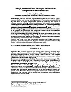
J. Appl. Sci. Res., 5(10): 1285-1297, 2009 res pectively. The s hafts were cut to the lengths of 250, 200, and 300 res pectively t o fit the input gear and the intermediate gear arrange me n ts s ee Figure 2. The intermediate gear was an arran gement of two 330 by 170 and 190 by 100mm bevel gears which were fit t e d t o g e t her to form the unit. The two main drive s ha ft s were c o n n e c ted to the intermediate gear through a s et of aligning roller ball bearings and flanges . The d e w atering s crews were connected to the drive s h a ft through a s et of bevel gears and aligning ball bearings . The dewatering s crew s w e re held in a bottom plate by a s et of aligning roll ball bearings . T w o bars of phos phor bronze material which has high res is tance to wear and tear at high friction, were taken. The bars of diameter 100mm and length 120mm were turned on the lathe to g ive a plane s urface which was bored. They were internally threaded to 13 A cme threads as re q u ire d to the length of 120mm. The inner and o u t er diameters were 55 and 80mm res pectively, and this was the s crew follower which tran s p o rted the cas s ava pulp platform up and down the s c re w s . Threaded holes were made on the s crew followers through which bolts were us ed to s ecure the cas s ava pulp platform. Though the output power of the machine by des ign was about 3 hp, it was found neces s ary to us e a 7.5 hp s ingle phas e motor to drive the dewaterin g ma c hine. This followed trial tes ts with 3.5, 5 and 7.5 hp motors which were availab le , t hat s howed the 7.5 hp motor to have dewatered the cas s ava pulp mos t efficien tly and at s hortes t time. The s ame 101.6 x 203.2 x 101.6mm U-channel of length 500mm was us ed t o ma ke the cas s ava pulp p la t form. The pulp platform were bolted to the s crew follower with the flat s urface of the two c hannels facing each other. The vertical d o u ble s queeze cas s ava pulp dewatering machine is s hown in Figure 1.
Fig. 1: Cas s ava Pulp Dewatering M achine
1291
Machine Tes t and Performance Eval uation: The s amples of ca s s a v a pulp that were tes ted were taken from thos e in popular us age in Nigeria. There are t w o types , the “fine gari” and the “Kpokpo gari” or “coars e gari” v arieties . The fine gari cas s ava pulp, 85% fines s , and the coars e or Kpokp o g ari cas s ava pulp, 65% fines s were tes ted on the dewatering machine. Fine cas s ava pulp was put into a jute s ack which was tied at the n e c k a nd weighed. A weight of 13.40kg was recorded. The pulp was placed on t h e machine platform. The motor was activated and the top and bottom platforms moved towards each other. The two platforms met and dewatering took place for 2.35 minutes . The res id u a l mas s was weighed, and water los s noted. The partially dewatered pulp was placed bac k o n t he platform and the machine was reactivated for 1.37minutes . A g a in the res idual mas s was weighed a fter the toxic water was partially driven off. T h e dewatering experiment was then carried out at interval of 5 minut e s a n d records were taken as entered on Table 1. T h e percentages of water was calculated. The experiment was repeated for the coars e c a s s ava pulp of 65% fines s . The record was entered on Table 2. The average of 5 s ample tes ts are s hown fo r e a c h of the fine and coars e pulps .
RES ULTS AND DIS CUS S ION By des ig n , values of the compres s ive s tres s and s hear s tres s for each of the dewaterin g s crews were 67.65 and 31.95N/mm2 res pectively. T h e s e gave a maximum principal s tres s in tens ion and compres s ion for s crew of 80.35N/mm2 . To ens ure that s crew d id not fail, 100N/ mm2 was us ed in the des ign as the maximum principal s tres s . The ma ximu m s hear s tres s by calculation was 46.52N/mm2 . The choice o f 60N/mm2 w a s made for the maximum s hear s tres s to ens ure the s afe operation of the s c re w in s hear. The total torque of each dewatering s crew as des igned was 1182kNmm. The s crew follower, which trans ported the cas s ava pulp for dewatering, w a s des igned to have 13 threads . The s hear s tres s induced in s crew an d t hat induced in t he follower were 17.76 and 14.69N/mm2 res pectively . Therefore the bearing pres s ure was a d e q u ate at 18N/mm2 . The tearing s t re n g th of 50N/mm2 was us ed to des ign for a s crew follower externa l d iameter of 100mm which was robus t and s afe. The us e of the des ign load and variation of 240kN was us ed to derive a s c re w length of 800mm as s hown in Figure 2. T h e bevel gears that were us ed were s elected to ca rry a s tatic load, dynamic load and maximum tangential tooth load of 19.8, 1.07 an d 9.05kN res pectively. The s tatic load was greater than 1.35 times t h e d y n amic load and the wear load was als o great e r t h a n the
J. Appl. Sci. Res., 5(10): 1285-1297, 2009 dynamic load for des ign t o be s afe. The efficiency of the gears was des igned to be low at 40%. This was becaus e an input s ingle phas e motor 7.5 hp was us ed at more than twice t h e output power, 3 hp, to ens ure rapid dewatering and dura b ilit y . T h is machine dew atered 200kg cas s ava pulp of 80% mois ture to 25% mois ture in about 34 minutes . The machine frame was de s igned to the load of cas s ava pulp, pulp platform, dewaterin g s crews , power s hafts , bevel gears , intermediate gear, input s haft and s ingle phas e mo t o r. W hen the s ack full s ample of fine cas s ava pulp 85% fine s s w a s s queeze by the dewatering machine, toxic water, milky b ro wn in colour flowed out. The flow of toxic w a t e r s lowed down after a while to trickling rate, then dripped and the drops were s lower in forming. T h e s ack containing t h e s ample was removed from the machine and w e ig hed. The dewatered pulp weighed 11.50kg whic h gave a percentage water los s of 14.18% , s ee Table 1. W he n t h e partially dewatered pulp was again dewatered, the drips were s lower in forming, and after 1.37 minute they appeared to have ceas ed. It was found to weigh 10kg, which placed th e p e rcentage water los s at 13.04% . t he s ubs equent changes in the dewatering tes ts was d o n e at 5 minutes interval. The final s ample weight at the end of 33.72minutes was 4kg, which gave a water los s of 70.15%.
T he coars e pulp s ample, 65% fines s , was ca rrie d out through the s ame tes t a s above, s ee res ults on Table 2. T h e toxic water dewatering rate was found to be s lower than that of the fine g a ri b y about 3.75%. this was becaus e th e c o a rs e pulp s tores more toxic water than the fin e g a ri becaus e of its grain s ize, and took longer time to give up its water. Con c lus ion: The vertical double s queeze cas s ava pulp dewatering machine was des igned for a cas s a v a pulp capacity of 200kg or 4 bags . The dewatering s crews operated a t a maximum principal s tres s of 100N/mm2 , ma ximum s hear s tres s of 60N/mm2 and at a total torque of 1182kNmm. The s crews which were made with acme thread, had exte rn a l and internal diameters of 55 and 45.5mm res pectively a n d w e re 800mm in length. The s crew followers which trans p o rted the pulp p latform up and down the s crew were des igned w it h induced s hear s tres s in the s crew and in the follo wer of 17.76 and 14.69N/mm2 re s p e ctively. Bevel gears were u s e d w h ich carry a s tatic, dynamic and maximum tangential too t h lo ad of 19.8, 1.07 and 9.05kN res p e c t iv e ly. The efficiency of the gears was compromis ed for s peed in dewatering. It was 40% in o peration becaus e a relatively large s ingle phas e 7.5h p motor was us ed.
Fig. 2: The Sectional view of the Cas s ava Pulp Dewatering M achine
1292
J. Appl. Sci. Res., 5(10): 1285-1297, 2009
Fig. 3: The gear arrangement
Fig. 4: Compound s crew arrangement
Fig. 5: A cme Thread s pecifications
Fig. 6: Showing line of action of forces in a gear tooth
1293
J. Appl. Sci. Res., 5(10): 1285-1297, 2009
Fig. 7: Reduction gear ratio Table 1a: Value of allowable static stress (ä o ) Material Allowable static stress (ä o ), (N/mm 2 ) Forged Carbon Steel (Casehardening) 126 --------------------------------------------------------------------------------------------------------------------------------------------------------------------------------Forged Carbon Steel (Untreated) 140 – 210 --------------------------------------------------------------------------------------------------------------------------------------------------------------------------------Forged Carbon Steel (Heat treated) 210 – 245 Table 1b: Result of dewatering fine cassava pulp at 80% moisture Mass of Cassava pulp Dewatering period (minutes) Final dewatered pulp (kg) T oxic water loss (kg) Percentag e T o x i c w at er loss (%) 13.40 2.35 11.50 1.90 14.18 --------------------------------------------------------------------------------------------------------------------------------------------------------------------------------11.50 1.37 10.00 1.50 13.04 --------------------------------------------------------------------------------------------------------------------------------------------------------------------------------10.00 5.00 8.50 1.50 15.00 --------------------------------------------------------------------------------------------------------------------------------------------------------------------------------8.50 5.00 7.40 1.1 12.94 --------------------------------------------------------------------------------------------------------------------------------------------------------------------------------7.40 5.00 6.40 1.0 13.51 --------------------------------------------------------------------------------------------------------------------------------------------------------------------------------6.49 5.00 5.40 1.0 15.63 --------------------------------------------------------------------------------------------------------------------------------------------------------------------------------5.40 5.00 4.60 0.8 14.81 --------------------------------------------------------------------------------------------------------------------------------------------------------------------------------4.60 5.00 4.0 0.6 13.04 --------------------------------------------------------------------------------------------------------------------------------------------------------------------------------T OT AL 70.15%
Table 2: Result of dewatering coarse cassava pulp at 80% moisture Mass of Cassava pulp Dewatering period (minutes) Final dewatered pulp (kg) T oxic water loss (kg) P ercentage T oxic w at er l o s s (% ) 13.40 2.35 11.70 1.70 12.69 --------------------------------------------------------------------------------------------------------------------------------------------------------------------------------11.70 1.37 10.20 1.50 12.83 --------------------------------------------------------------------------------------------------------------------------------------------------------------------------------10.20 5.00 8.80 1.40 13.73 --------------------------------------------------------------------------------------------------------------------------------------------------------------------------------8.80 5.00 7.60 1.20 13.64 --------------------------------------------------------------------------------------------------------------------------------------------------------------------------------7.60 5.00 6.70 0.90 11.84 --------------------------------------------------------------------------------------------------------------------------------------------------------------------------------6.70 5.00 5.70 1.00 14.93 --------------------------------------------------------------------------------------------------------------------------------------------------------------------------------5.70 5.00 5.00 0.70 12.28 --------------------------------------------------------------------------------------------------------------------------------------------------------------------------------5.00 5.00 4.50 0.50 10.00 --------------------------------------------------------------------------------------------------------------------------------------------------------------------------------T OT AL 66.40 %
1294
J. Appl. Sci. Res., 5(10): 1285-1297, 2009 Nomenclature Symbol Meaning Unit IIT A International Institute for T ropical Agriculture --------------------------------------------------------------------------------------------------------------------------------------------------------------------------------W Load kN --------------------------------------------------------------------------------------------------------------------------------------------------------------------------------As Area of screw mm 2 --------------------------------------------------------------------------------------------------------------------------------------------------------------------------------óy Yield stress kN/mm 2 --------------------------------------------------------------------------------------------------------------------------------------------------------------------------------F.S Factor of safety --------------------------------------------------------------------------------------------------------------------------------------------------------------------------------ds Diameter of screw mm --------------------------------------------------------------------------------------------------------------------------------------------------------------------------------do Outer diameter of screw mm --------------------------------------------------------------------------------------------------------------------------------------------------------------------------------dc Core diameter of screw mm --------------------------------------------------------------------------------------------------------------------------------------------------------------------------------P Pitch of thread mm --------------------------------------------------------------------------------------------------------------------------------------------------------------------------------a W idth of top of thread mm --------------------------------------------------------------------------------------------------------------------------------------------------------------------------------c W idth of the bottom of thread mm --------------------------------------------------------------------------------------------------------------------------------------------------------------------------------h Height of thread mm --------------------------------------------------------------------------------------------------------------------------------------------------------------------------------d Screw mean diamete rmm --------------------------------------------------------------------------------------------------------------------------------------------------------------------------------o á Helix angle --------------------------------------------------------------------------------------------------------------------------------------------------------------------------------o ö Friction angle --------------------------------------------------------------------------------------------------------------------------------------------------------------------------------o â T hread angle --------------------------------------------------------------------------------------------------------------------------------------------------------------------------------ì Coefficient of friction --------------------------------------------------------------------------------------------------------------------------------------------------------------------------------óc Compressive stress N/mm 2 --------------------------------------------------------------------------------------------------------------------------------------------------------------------------------ô Shear stress on the screw N/mm 2 --------------------------------------------------------------------------------------------------------------------------------------------------------------------------------T T orque on screw Nmm --------------------------------------------------------------------------------------------------------------------------------------------------------------------------------Principal stress in compression N/mm 2 --------------------------------------------------------------------------------------------------------------------------------------------------------------------------------ód Value of stress N/mm 2 --------------------------------------------------------------------------------------------------------------------------------------------------------------------------------ôd Value of shear stress used N/mm 2 --------------------------------------------------------------------------------------------------------------------------------------------------------------------------------Maximum shear stress N/mm 2 --------------------------------------------------------------------------------------------------------------------------------------------------------------------------------Screw follower bearing pressure N/mm 2 Sfb --------------------------------------------------------------------------------------------------------------------------------------------------------------------------------n Number of threads in the screw follower --------------------------------------------------------------------------------------------------------------------------------------------------------------------------------ôs Shear stress induced in screw N/mm 2 --------------------------------------------------------------------------------------------------------------------------------------------------------------------------------ôsf Shear stress induced in the follower N/mm 2 --------------------------------------------------------------------------------------------------------------------------------------------------------------------------------ôt T earing stress N/mm 2 --------------------------------------------------------------------------------------------------------------------------------------------------------------------------------D1 Calculated outer diameter of follower mm --------------------------------------------------------------------------------------------------------------------------------------------------------------------------------Ps Design load plus variationk N --------------------------------------------------------------------------------------------------------------------------------------------------------------------------------I Second moment of area of the screw mm 4 --------------------------------------------------------------------------------------------------------------------------------------------------------------------------------Ls Length of screw mm
1295
J. Appl. Sci. Res., 5(10): 1285-1297, 2009 Continue äo Allowable static stress N/mm 2 --------------------------------------------------------------------------------------------------------------------------------------------------------------------------------Cv Velocity factor --------------------------------------------------------------------------------------------------------------------------------------------------------------------------------V Peripheral velocity mm/s --------------------------------------------------------------------------------------------------------------------------------------------------------------------------------b Face width of tooth --------------------------------------------------------------------------------------------------------------------------------------------------------------------------------m Module mm --------------------------------------------------------------------------------------------------------------------------------------------------------------------------------D Gear diamete rmm --------------------------------------------------------------------------------------------------------------------------------------------------------------------------------Tn Number of teeth --------------------------------------------------------------------------------------------------------------------------------------------------------------------------------y T ooth form factor --------------------------------------------------------------------------------------------------------------------------------------------------------------------------------L Cone distance mm --------------------------------------------------------------------------------------------------------------------------------------------------------------------------------Do Pitch diameter of gea rmm --------------------------------------------------------------------------------------------------------------------------------------------------------------------------------DP Pitch diameter of pinion mm --------------------------------------------------------------------------------------------------------------------------------------------------------------------------------WD Dynamic load N --------------------------------------------------------------------------------------------------------------------------------------------------------------------------------Ta Actual torque at the 3 rd stage Nmm --------------------------------------------------------------------------------------------------------------------------------------------------------------------------------WT T angential tooth load N --------------------------------------------------------------------------------------------------------------------------------------------------------------------------------Ws Static tooth load N --------------------------------------------------------------------------------------------------------------------------------------------------------------------------------BHN Brinell Hardness Number --------------------------------------------------------------------------------------------------------------------------------------------------------------------------------äc Flexural endurance limit --------------------------------------------------------------------------------------------------------------------------------------------------------------------------------Ww W ear load N --------------------------------------------------------------------------------------------------------------------------------------------------------------------------------Q Ratio factor for external gear --------------------------------------------------------------------------------------------------------------------------------------------------------------------------------K Material combination factor N/mm 2 --------------------------------------------------------------------------------------------------------------------------------------------------------------------------------ä se Surface endurance limit N/mm 2 --------------------------------------------------------------------------------------------------------------------------------------------------------------------------------Ep Young’s Modulus of pinion material GN/m 2 --------------------------------------------------------------------------------------------------------------------------------------------------------------------------------EG Young’s Modulus of gear material GN/m 2 --------------------------------------------------------------------------------------------------------------------------------------------------------------------------------o è Pressure angle of gear --------------------------------------------------------------------------------------------------------------------------------------------------------------------------------Po Power output from gear W --------------------------------------------------------------------------------------------------------------------------------------------------------------------------------Pi Power input W --------------------------------------------------------------------------------------------------------------------------------------------------------------------------------PCD Pitch circle diamete rmm Appendix I Nominal or Major diameter (do ) Minor or Core diameter (d c ) Pitch (P), mm Area of Core (Ac ), mm 2 30 23.5 434 --------------------------------------------------------------------------------------------------------------------------------------------------------------------------------32 25.5 511 --------------------------------------------------------------------------------------------------------------------------------------------------------------------------------34 27.5 6 594 --------------------------------------------------------------------------------------------------------------------------------------------------------------------------------36 29.5 683 38 30.5 731 --------------------------------------------------------------------------------------------------------------------------------------------------------------------------------40 32.5 830
1296
J. Appl. Sci. Res., 5(10): 1285-1297, 2009 Continue 42 34.5 7 935 --------------------------------------------------------------------------------------------------------------------------------------------------------------------------------44 36.5 1046 46 37.5 1104 --------------------------------------------------------------------------------------------------------------------------------------------------------------------------------48 39.5 1225 --------------------------------------------------------------------------------------------------------------------------------------------------------------------------------50 41.5 8 1353 --------------------------------------------------------------------------------------------------------------------------------------------------------------------------------52 43.5 1486 55 45.5 1626 --------------------------------------------------------------------------------------------------------------------------------------------------------------------------------58 48.5 1847 --------------------------------------------------------------------------------------------------------------------------------------------------------------------------------60 50.5 9 2003 --------------------------------------------------------------------------------------------------------------------------------------------------------------------------------62 52.5 2165
W hen the average of five s amples of fine c a s s ava pulp of 80% mois ture content were dewa t e re d to the mois t ure level of 29.85% it took 33.72minutes , s ee T a b le 1. The average of five s amples of coars e pulp , 65% mo is t ure content, were dewatered in the s ame time of 33.72 minutes 80% mois ture content to 33.6%. The coars e cas s ava pulp dewatering rate was found to be s lower than that of the fine gari by 3.75%. The clos es t in performance to the vertical s q u e eze c a s s ava pulp dewatering machine was the IITA M ult iPurpos e batch type dewaterin g machine. The new motorized vertica l s queeze dewatering machine was 7 t imes fas ter in dewatering than the manual IIT A machine. It a ls o removed 10 to 20% more toxic water from cas s a v a p u lp than the IITA machine. The rate of gari production w a s 7 times more with new machine than with the IIT A ma c hine, and was about 40 times fas ter than the local method. T h e new vertical s queeze d e w atering machine will caus e more Nigerians to b e fed, as more will be produced. Through this , development will be enhanced. ACKNOWLEDGMENT The authors acknowledge M r. Raji and M r. S. A rinde for their help during the fabrication of the machine. A ls o acknowledg e d are O. M edaiyes e, M . Badru d e en, T. Ojo and E. Oladimeji for their as s is tance in the tes t exercis e.
REFERENCE 1.
A kinrele, 1962, “The M anufacture of gari from cas s ava in Nigeria” Firs t International congres s on food technology, London
1297
2.
Ra ymond, F.N., 19825. “A pplied Strength o f M aterials , John W illey and s ons , New Yo rk, 304321. 3. Khurmi, R.S. and Gupta, J.K., 2005. “A Textbook of M achine Des ign” Euras ia Publis hing Hous e (PVT) LTD, Ram Nagar, New Delhi, 110-055: 509 - 552, 624-673: 963-990. 4. Lewis , W .P. and A .E. Samuel, 1984. “Fundamental of Engineering Des ign” P re n t ice Hall Publis her, 68. 5. P ierre, S., 1989. “Cas s ava” The Tro p ic a l A griculturis t, 1st Edition CTA M acmillan, 20-61. 6. Davids on, S. and J.F. Brock, 1979. “Cultivation of cas s ava” 1st Edition, M cGraw Hill Book c ompany, London, 150-159. 7. Eghareuva, O.M ., 1990. “Des ign and cons truction of cas s ava pres s ing machine”, Project Re port, Department of A gricultural Engineering, Univers ity of Ilorin. 8. Okato r, N ., 1983. Proces s ing of nigenan Indigenia n s Food, A chance for Innoration, Nig. Food J. 1: 23-32. 9. A jibola, O.O., 1987. Eqnilibrinm mocs turen Pruper this of winged bean Seed, Trams actio n of A SA E, 28(5): 1485-1493. 10. IITA Food Net, 2007. “Double Screw Pres s ” A groenterpris es manual proces s ing equipment, Pos tHarves t Engineering Unit, IITA , Ibadan, 1-5.