and data processing systems development using a method called LSDM. ... was pioneered in the Xerox Star system and made
SOFTWARE-PRACTICE AND EXPERIENCE, VOL. l9(+),371-391(APRIL 1989)
The ECLIPSE User Interface Department
of Computing,
IAN Uniaersity
SOMMERVILLE of Lancaster, Bailigg,
RAY
Lancaster
IAI
4YR, U.K.
WELLAND
Department of Computing Science, Uniaersity of Glasgow, Glasgow GI2 8QQ, U.K. STUART POTTER Software Sciences Ltd., Deanway Technology Centre, Wilmslow Road, Handforth, Wilmslow, Cheshire SK9 3ET, U.K. AND JOHN SMART CAP Group Ltd., 4044 Coombe Road, New Malden, Surrey KT3 4QIt, U.K.
SI.JMMARY This paper describes the user interface facilities of the ECLIPSE integrated project support environment. This interface is based on a consistent metaphor called the'control panel'metaphor and includes standard help and message-handling systems. The paper describes these as well as some of the interface standards which have been developed. The interface has been interface', which provides a portable, hardware-indepenimplemented on top of the'applications dent interface for software tools. KEy woRDs Softwareengineeringenvironment User interface ECLIPSE
Help system
INTRODUCTION ECLIPSE is a large-scaleintegratedproject support environment(or IPSE) which has been built in the U.K. by a consortium of universities and systemscompanies. It is a database-centredenvironment with the databaseprovided by PCTE (portable common tool environment), an emerging European standard on which environments can be built. ECLIPSE is intended to be a general-purposeenvironment which may be tailored to support a variety of application domains, but the initial versions of the system will concentrate on supporting real-time systems development using MASCOT and Ada and data processingsystemsdevelopment using a method called LSDM. An early design decision made in the ECLIPSE project was that integration should not simply be at the databaselevel but that the user interface (UI) should also present an integrated system view. As ECLIPSE IPSE products are intended for releasein the late 1980s, it was decided that the user interface should be tailored exclusively to bit-mapped high-resolution workstations. This decision allowed us to assumethat each engineer'sworkstation would have significant local processingpower and meant that
r-2 I $10.50 0038-0644/ 89I0+037 & Sons,Ltd. 1989 by Wiley John @)
Receiaed 7 December 1987
372
I.
SOMMERVILLE
ET AL.
we could design an interface which is based on graphics rather than on command languageinteraction. When this work beganin 1984,no other IPSEs had been developed,and bit-mapped workstationswere only just becoming available.There was no directly *f*""iiii"rature on which we could baseour work. However, concurrent with the wlrk described here, the ASPECT IPSEl adopteda different, more fundamentalapproachto user interface construction.2 Rather tfT_!gi]g on top of existing facilities^(and therefore live with their limitations), the ASPECT projeit developei a compleie user-interface sysrem from scratch, including a window -utt"g".. This allowed a uery "";i.,.;;--oa"t or user interactionto be presented.This afproach was not adopted in ECLIpSE partly becausewe felt that the practical advaniages(cost, reduced risk, pott"Uiliig io U" gained.by reusing,existing.software(such "r ih. workstation *indo* -"rr'ui.-.rrt system.)outweighed the limitations (lack of consistencyand predictability) this'sometimes imposed. The lack of directly relevant work in this application domain also posed difficulties when we came to consider fundamentals of cognitive sciencewhich ttlight t" l"t.r,urrt to our work. AlthoLrgh work- by Price and Cordova3 on the use of ,io,r.. buttons, Tullisa on menu design and Marcuss on screen design was taken into account, those cognitive scientists with whom we discussed.the gineral problem had difficulty in understanding the concept of an IPSE, and ultimatily presentedadvice which was so as to be useless.However, more recent work (not available to us when :"lJT!lL"ry ECLIPSE was designed) such as rhat described by Dix et )1.6 -uy ;;;; .!t"uu.t to environment-interface design, as these workeis are considering this uppti"utio., domain. development environments such -I"-ll!"_ .as Interlisp,T Cedars or Smalltalk,e ECLIPSE is.an open environment and is not integrated aiound a single progru;-furg language. The tight tool integration between lanluage and supporitoot. |ffered in single-languageenvironments could not be provide"d.F.ather,we adopted ur upprou"f, was 1v-hic.h pioneered in the Xerox Star system and made generally kno*r, in th^e'Apple Macintosh, whereby all tools adopted ^ to--or interfaci style and made use of a set of standardroutines to createtheiiuser interface. A detaileddlscription of the ---- aDoroach -rr^ adopted, called Control Panels,is given by Reid and Welland.r0 part of ..As .the provision of a consistent framework of interaction, we decided that all messages,includinghelp texts, from the environment to the user should be presented in a similar fashion. This can be accomplishedby defining standards, but w! decided that a more reliable.and approach was to piovide a standard -essaging :g.j-:lfg"Jltj system which is used by all ECLIPSE tools. In practice, we discoveredthat help texts are quite different from other messages,so we irave built a separatehandler for help texts and have a mandatory requirement that all tools should provide help frames describing their use. This paper is exclusively concerned with a general presentation of the ECLIpSE user interface and does.not describe specific tools developed during ttre BCiipSB project. We present a brief overview of ECLIPSE and describe tlie user interface metaphor which is a standardapproachfor interactingwith all ECLIpSE tools. The interrelated help_and messagesystemsare then descri6ed and, finally, -" dir"r.. o.r, approach to implementation. initial proto_typeimplementation of the ECLIPSE UI was as a set of C programs .The which interacted directly with the facilities provided on Sun workstations. However,
THE ECLIPSE USER INTERFACE
373
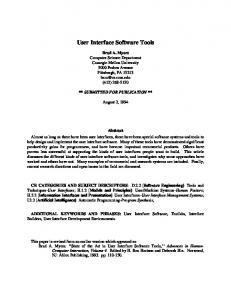
the decisionto baseECLIPSE on PCTE, which providesits own set of UI primitives, and the commercial requirement of portability meant that we needed an alternative which was less closely tied to Sun library software. approach 'Thn. 'applications we have based the final UI implementations on what we call the interface'. This is an interface layer between ECLIPSE applications and the UI primitives provided by the workstation. In ECLIPSE, the applications interJacehas L."n -uppld onto the underlying SunView primitives and, at the time of writing, an implementation using the PCTE UI facilities is under way. thi. p"p"t descriLes a development project rather than a research project. Our objective *". to build an interface to a very complex system which helped the_user to master that complexity; we did not set out to carry out fundamental researchin UI design nor to build a generalizeduser-interfacemanagementsystem. All of the software desciibed here has be-enwritten in C, is currently operationalon Sun workstations and is now shipped as part of the ECLIPSE IPSE product marketed by the industrial collaboratorson the ECLIPSE project. THE ECLIPSE ENVIRONMENT ECLIPSE is a software engineering environment which has been developed in the U.K. It is a large-scaleprojict (150+ person-years)which has been implementedby three systems cJmpanies and three universities with funding support from the Alvey Directorate.The Alvey Directoratemanagesthe U.K.'s nationalresearchprogrammes in software engineering, VLSI, artificial intelligence and user-interfacedesign. ECLIPSE runs on Sun workstations and provides an object-managementsystem built on top of PCTE along with a number of tools which are geared towards the support of ioftware design. The system provi{{:s_39c_t1t9fine-grain_d.at1bVmaking usi'of a two-tier database.llThe structure of ECLIPSE is illustrated in Figure 1. The tools which are available in the initial version of ECLIPSE include a generic design-editing system which may be tailored to support any design T"!!9d based on diagiammatiC techniques,12an Ada cross-compilationsystem for Intel 286 processors
Figure I. The structure of ECLIPSE
374
I.
SOMMERVILLE
ET AL.
and associatedhost tools to support that- Ad_a 13 system for -sJstem, a design-support ""-i.*i"riethod MASCOT and a design s.upport system for LSDM. nlescoi% ir for real-time systemswhich is *iaeiy used in the.Europear,def.n"e ";-;;;i?;. lsonr is a.developmentof SSADMIs whicir has been adopted as a U.K. Government standard and which is used, fairly w.idely, in Europe"r, "rd in some u.s. organi;;;i;;.' As well as the work describedhere, other work in the general areao"fuser interaction with software-engineeringenvironments has been carriet out as part of the ECLIpSE project. This has involved investigatingthe use of iconic interfaces t.;r";i; "r*irorrments and developing a-generic graphical editing system. However, u"'trri. work is peripheral to the main.Ul progtamme, we have ioicorrered it here. e' ou"rui"* or the,PCL,IPSE system is given-by Alderson et al.r6 and a comprehensive description bv Bott. 17 "ECLIPSE is built.on top of the portable common tool environment, pCTE,rs, rs which was develop-eqjJ i consortium of European countries as a common basis tor envrronments' PCTE provides an object-managementsystem based on an entity relationship model that.managesa databasl distribuied over a network of workstations. It also primitives fJr user-interface.support"rrd p.o""rs management. .provides It is compatible with Unix System V so that Unix applicationi may run without change under PCTE. METAPHORS AND STANDARDS In designing an integrated interface to ECLIPSE there were two distinct problems to consider. How should the interfacesof individual tools be represented and what should the overall environment in which ECLIPSE tools execute ilok fike? System.-..r"t ". the-Apple Macintosh.havean instantly recognizable'housestyle'which i..r..Jio, ull tools' Anapplication has a menu bar acrossi19 t9n, giving accessto pull-down menus, each window used by the_applicationhas a title nui,"*tri""tr can be used for moving or closing the window, scroll bits ate standardized,etc. We wished to design " .ir"1"rfy recognizablehouse style for ECLIPSE and to ensure that tools behavei consistently d"tllg common operations such as start-up and shut_down. best developed-examples of integraied user interfaces are those based on the .'oesk-top, Ih" metaphor'^we- argr.rethat this mctaphor is not relevant for the majority of the user roles identifie{ {gr ECIIpSB, and our observationssuggestthat explrienced software engineersfind this type of interface counterproductive. The reasonfor this is that its'principal entities ate office documents with a limited set of allowed ope.alions such as move, delete,.etc- Softwa-reengineersare concerned with p;;;r;;:;J.igr. and specificationswhich have different sets of allowed operations (such as compile, link,. check, etc.). The number-of possibleoperationsappfied to softiare is, typ1c"1y, much larger than those allowed using the. desk-top *.iaphor, and the op.r#|r. ur. not readily represented using simplelconic representations. The facilities provided by the window-managementsystem of a workstation, such as the Sun, are aime$ at^9lPert users. They are"not suitable in their raw form for the lesstechnical users of ECLIPSE. Therefori, *" looked for some compromise between the easy-to-understandbut simplistic desk-top metaphor and the terse command -gr"pt lanoffered by systems such as Unix. In short, we sought to devetop 9""99 u i""f interface with sufficient functionality for the more experiJnced .r.".. -- - Th" ipp'ro""r, which was finally adopted is termed the 'control panel" metaphor.
THE
ECLIPSE USER INTERFACE
J/)
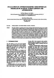
Control panels The concept of control panels was introduced to provide the unifying metaphor for the ECLIPSB Ut. The objective is to stimulate the control panelswhich are available with many complex pieces of equipment, to provide both status information and controls. Analogbus concepts are provided within ECLIPSE software 99n1r9l panels. One lesson to be learned from hardware control panels was to avoid information overload, the extreme example of which is probably an aircraft cockpit. Fortunately, much of the information can be hidden using menus, thus avoiding having a screen full of control and status information. We identified five basic types of objectswhich are sufficient to provide the necessary functionality in our control panels. L Button. A button is an object which when picked ('pressed') always initiates a single action, such as screen dump. Every time a button is picked it initiates the same action, its effect is not context dependent. 2. Menu. A menu displays a list of objects one of which can be chosen by the user to initiate some action; a typical use is command selection.The contents of menus may depend on the context in which the user is working. 3. Stite silector. A state selectoris a composite symbol consisting of a menu and a value. The value displays the current state and the menu provides a mechanism for changing that state. An exampleof the use of a state selectoris in representing multiple-modes; the value part of the state selectorshows the current mode; this value-can be changed by selecting the new value from the associatedmenu. 4. Sign. A sign is a two-part object which has a fixed title and a value. The value pait tttay bl static, dynamic (changedby the system) or user-changeable.A static iign might be used to display the name of the current user, whereas a dynamic sign could be used for the display of error messages.A user-changeablesign might be used in an editor to display the name of the file being edited. To save *oik to a different file, the user simply overtypes the old file name in the sign with the new. 5. Light. A light is an indicator with a binary status, either on or off. Lights are commonly used to indicate whether a window is current, that is, the window to which the keyboard is attached, or a processis busy. Once we had identified these basic objects, we designeda set of icons to represent them. The set of shapes shown in Figure 2 is the result of experimenting with different possibilities. AJ the project has progressedvarious minor changeshaveteen made to ihese icons. The guiding principles for designing the shapeswere that they needed to be easily distinguiihable and sufficiently regular that they could easily_be.fittedinto a ,""ron"tl. arealnd could contain text labels. Although we acceptthat the icons chosen may be less than ideal from a graphical design point of -view, the overriding pragmatic space.The userconsiderationwas the need to make most effectiveuse of scarcescreen 'Title' in Figure 2 includes the visual cue '-)' to indicate that changeablesign labelled the uier may provide an input by typing into the value part of it' Provision is made for a two-state light to reassurethe user that the system has not crashed when a long operation is taking place. Tools should arrange for the light to 'flash' during time-consuming operations to indicate to the user that the system is still active.
376
I.
SOMMERVILLE
ET AL.
ffiffiffi Signs
ffi Buton
I M.^,
iem I selectcd I ldenu
SEtteselectc
M,
.
-l
State 2
/
\
Ughts
Figure 2. Control panel object representations
The ECLIPSE UI uses the concept of a_c_ontrolpanel as the principal means of controlling the major functions of both ECLIPSE as a whole una itraiyiaual applications, such as a design editorrz that run under ECLIPSE. However, tt " "orrtrotpanel metaphor, like most metaphors, is not the answer to all probl.-.. 1.n. "orrtrot panel is primarily of use for sele-ting options, setting contextuaf information, in.,roking infrequently used major actions and invoking critiial actions. Frequently r*J "o*mands that cannot be easily grouped "t" no1 sensible contendersio, p"n.l buttons since the user would. spend a gteai deal of time 'mousing' around the control p"""f . .For example, consider a text editor. The general movJment and editing commands within the text should be accessedvia some other mechanism, such is kevboard commands, function keys etc. conversery, file selection, editing *oJ., d"p12l/ mode etc. would be suitable actions for invocation via the_conirol pan"elusing, roi ll"-pt", menus or buttons. Similarly, actions such as invoking the help systelm, "f".l"L ln. yiL{9*' aborting or terminating the application should6e provided ".i"g io";ii"r,.t facilities. Control panel layout standards Once we had settled on a set of conceptsand symbols we neededto ensureconsistent oj these objects by defining controi panel layout conventions. It was in this area 5e that fundamental work such as that of Marcus,s"Priceand Cordov"l"nJE;;"1^ *". most useful. Basedon this work, we formulated a number of outline standards r?garding the design of menus and the use of buttons in ECLIpSE. 1. M-enu options should be centred on a block basis rather than on a per-line basis. 2. The ordering of options within a menu should reflect a logical gr";ii;g ";iopriate to the task at hand. 3. Frequently used or safe actions should be placed at the top of a menu, less fjlq_"_"I4y used or unsafe actions should be placed at the bottom. . 4. ECLIPSE butto-nsare provided for both ,rn."i" actions, such as'exit', and actions which do not fall naturally into a logical grouping, such as ,help'. 5. A user selection from a menu should be confiimJd visually by inversion. To achievevisual consistencywe recommendrelative positions for the various oblects within the.control panel. Signs.shouldappear to the lefi of the contJ p-"i, irri;*.a by state selectorsand menus, then buttons and hnally lights to the righi of the "orrtrot
THE
ECLIPSE USER INTERFACE
377
panel. However, the designersof control panelsoften found good reasons(or excuses!) io ,,"ry the positions of the objects. An example of a typical control panel taken from the ECLIPSE help system is shown in Figure 6. The details of application control panels vary, but certain objects appear in.nearly 'Exit' button should always be provided and.every all control panels. Fbr """*ple, an tool should use this button in a consistentway. The implementation of exit is obviously but confirmation of exit without updating is always required. application-dependent ' in gene.ul, confirmation of destructiveactionsmust be provided via a pop-up selector contai"ningvisual targets. The action must be confirmed by positioning the cursor over unambiguous atarget uid "li"kingi *on." button. The wording of the_targetsmust be -wrong target. and Ihey must be far enough apart to prevent accidentally hitting the The Sun software automitically includes a'name stripe' at the top of every window created; it cannot be removed without modifying the window manager' therefore we decided to standardize its use. In ECLIPSE, the name stripe is used to display the name of the component associatedwith the window and the component version details. Screen organization standards At the beginning of the project we attempted to define a generalscreenorganization, suitable for"a variEty of appfibations. Our objective was to establish a convention for screen organization so tfrai- aimerent tools presented a consistent window interface to the user.-Th.r. we hoped to recommend window sizes and layouts but toolmakers or end-userscould change these if warranted by particular circumstances. In principle, the w-orkstation's19 inch screenwas capable of holding tyo windows side bv sidi. where each window is the size of a normal (A4) piece of paper' We thought it desirable to be able to view two large windows simultaneously, as well as smalier windows, but the limited screen size meant that a double ,{4 display left no room for console windows, status displays or'parking' of icons' Experiments were carried out using a number of different founts available on the S.rn io try and achieve a compromist between a comfortable fount size and a usable display aiea. The recommended aspect ratio for windows is that the sides should be 'goldett rectangle'.zrAn attempt to define landscape in the ratio one to root two or windows to fit this ratio, in the sime orientation as the screen, led to windows which were either too shallow to be usable or so large that only one would fit on the screen! Our preferred layout was to have two portrait windows, in the recommendedaspect tut the only fount *hich would allow this was too small to read. ratio, juxtaposed, ^a readable fount was chosen and windows defined to be the maximum Thereiore, length which can be obtained, producing an aspect ratio of about 1 to I'23. These wirido* dimensions are intended as guidelines for applications but some ECLIPSE tools, especiallythose using graphics, require a larger working area. Initialiy, we sought to avoid overlapping windows for the reasonsset out by Cohen et al.zz Overlappiig windows can bb-awkward to manage, waste screen space and difficult to find. bvirlapping windows tend to increasethe memory load on users and require them to be famiiiar with the window manipulation-facilities. A tiled solution was considered, but our need for large windows (particularly for editing) made us reject this approach.In practice, usersof ECLIPSE use overlappingwindows extensively becausi -"ny appiications seem to need larger windows than can comfortably be accommodatedin half of the workstation screen.
378
I.
SOMMERVILLE
ET AL,
In summarY: we failed to establish a workable standard for screen layout which would be applicable to all ECLIPSE users. Given thar screen sizes are unlikely to increasesignificantly (becauseof cost and the.p""" o"".rpied), we believe that it is probably impossible to achieve an acceptablestandard *h'.r" the user community is experiencedand diverse and where the applications require large windo* .i;... THE MESSAGE SYSTEM As well as the information displayed as part of the normal running of an ECLIpSE tool, there are occasions when i tool y+"! to outpui messagesto the user for information' errors'-diagnosticsetc. The ECLIPSE ;"'..;g" system provides the tool builder with the software to handle these messagesand piovides the user with some ability to choose how and when these messagesire dispiayed. One of the characteristicsof a project support enrrirorrment like ECLIPSE, is the wide variety of potential users and thiir. kno'r,vledge ""J rtiil.. A great deal of thought was given to how a messagesystem could accomirodate this varie"tyand still -"irrtui. a consistent approach. other systems have adopted a numb., oi "ppro".rr.. ir, "., attempt to solve th: including classifyingusers on skill levei .rr"h "s ,roui"", llPle1n, experienced' ^elperl, or .by layerittg -.-..ug.s io t-hat the user can repeatedly ask for more levels of detail. It is very difficult to i,rn. this sort of system as a user,sskill level may be -":l higher in one iask than another and he o, .li" may get frustrated with messageswhich are too terse or verbose. The method chosen for ECLIpsE involved three main design decisions: 1. Separatethe messagetexts from the code. 2. Structure the messagerexts. 3. Link messagesinto ihe help system. The first is fundamental .and involves grouping the messagetexts into messagesets. These sets are not built into a tool bui "r.-r.id at run-tirie. ih;.;il;; "ii;'-"ri"" messagesets to be provided without rebuilding the software. Thus -"..ug"-.;t. i' languagessuch as French or German can be p"roduced or1p."i"l, more explanatory messagescreated for training purposes. The objective of the -.s.ig-. is to be positive and guiding rather than negative and accusatoryso each messagecontains a brief summary"of the"problem and u s-uesestio. of what to do about it' The experienceduser who ,""og.rir"riir; ,,'"rl?a "" *tH further than the first few words whereasthe novice, ot i-"J"J the expert encounteringa messagefor the first time, may read the whole message. The structure of the messageis-equally importantlTh. rrr"..uges are single lines allowing-parametersubstitution so thai run-time specificinformation, such as the name of a databaseobject, can be incorporated. For."u-pr., u--L."g. in the systerr-igrr, Interaction: "writing to file $1 is not allowed; check file protection,,: Help-> Write protection. This specifiesthe TTS18e-type (Interac1i91), the messagetext where the parameter $1 can be substituted with th" hle nu-. which'the ,r.", L'. tried to access, i.rJ" lrrt to the help system.
THE EcLIPSE USER INTERFACE
379
If the messageitself is not sufficiently explanatory, the user can call for help. Each messagecan be linked to a frame of help information as described in the following 'Help'button, which section.To display the relevantframe the user simply selectsthe is availablefrom every ECLIPSE tool. The user then has accessto all the help frames relevant to the current context plus as much detail as has been stored in the help database.Displaying this information in a separatewindow of the workstation enables the help text to be viewed alongsidethe problem. The messagesystem and the help system are closely related. Their relationship is illustrated in Figure 3. Message types All ECLIPSE messagesare typed and the tool builder decidesat which points in the code a messageshould be generated.Generating a messagesimply involves specifying a messageidentifier plus any substitution parametersand a messagetype. Messagetypes fall into three classes: l. Interaction messages.These are messageswhich provide details of the status of an ECLIPSE interaction. The interaction messagetypes are information, warning, error andfatal. Messagesof this type are generatedby tools for users, although it must be emphasizedthat there is no need to indicate the messagetype to the tool user. 2. Input messages.These are messagesof type commentwhich allow usersto provide feedback to tool builders. 3. System messages.These are messageswhich provide system information and which are generated by tools for tool builders and system administrators. The types in this class are metric, diagnostic, traching, console, security and system. Comments are a way of capturing users' observationsabout ECLIPSE and any of its tools. During any session,a user is able to record comments about any probiems encountered or about any feature of the system which he or she likes or dislikes. Comment messagesare logged for subsequentanalysisby tool builders.
Helpframes
Itigure 3. The help and messaging systems
380
r. soMMERVTLLE ET AL.
.Having assignedthe type.,the tool generatingthe messagecalls the messagesystem, which extracts the required messageiext, prepends the tlpe descriptor anfi ,oL,". i, to a number of possible destinations depending upon the"type of the -...ug". Message routeing and logging One of the most irritating features of some software systems is the generation of l1Y1t9q-essages which interrupt a.user'swork. One of ihe design objEctivesoi,f," messagesystem was to allow users to control the messagesgenerated by Pqf-|ry-E ECLIPSE tools. Each ECLIPSE user has an associatedmessag.e log in which all generatedmessages may be retained. This faciliql was included to allow an evaluation 6f BCIIpSE usage and to record, in an unambiguous way, problems which users encountered with ECLIPSE software. Messagesmay be direcied to the log as well as the user's screen. In fact, the messagesystem recognizesthree possible dJstinations: (i) the usei's current window (ii) the console (iii) the user's messagelog. The destination of eachmessagetype is governedby a routeing table which allows users to-changethe destinationof messagesbeiweensessionsor betwieentool invocations.The table assignsto each messagetype zero or more of the possiblethree routes 1to igror. a class of routes are specified). For eiample, a user mighi *iih to .mes-sages,.zero suppressall information and warning messagesbut see"troi.. He or she m"ightchoose to display fatal messages.(messages which iesult from an unrecoverableerior) in the current window and on the console as well as recording them in the messageiog. All other types mighl be routed to the messagelog for lateianalysis. Any -essalg."i3gg"a e < are time-stamped and include extra information about the tool involved. of the system functions in ECLIPSE use the messagelog to record events Y""ysuch as loggTg_ol_and off, tool invocation and deletion, hence-pro'iiding an event log for a users' ECLIPSE session.The log is simply a texi file ani "un b"-pro"..."j U! any of the text handling utilities to produce repirts or statistical information. THE HELP SYSTEM O-n-linehelp syst^e^ms have been used extensivelyand with mixed successin a number of environments.23The prime objective of a help systemis to give usersthe information they need quickly and to assistthem to relate thai informatioir to the task in hand. All too often, users have to. searchthrough reams of information by which time they may have forgotten the original problem. Alternatively, by the time users return to their task, the details of the help information may have been forgotten! The ECLIPSE help system.attemptsto overcomeboth'these problems. First, it keeps track'of what the user is doing and offers context-related help; ,""onJiy, it displays the help text in a separatewindow thus allowing the user to compare that text with the output from the current task. In general, help systemscan be classifiedinto three broad rypes: (i) tutorials (ii) on-line manuals or referencevolumes (iii) memory job/contextual help.
THE
ECLIPSE USER INTERFACE
381
The ECLIPSE help system concentrateson providing context help together with a general browsing facility of availablefunctionality. No attempt is made to provide an interactive tutorial system. It has been recognizedthat ECLIPSE will include a growing number of tools which may be developed explicitly or may be brought in as foreign tools. The foreign tools may have their own help systems,and the ECLIPSE help system is designedto enable 'alien' systems to be, at least partly, integrated. As an example, ECLIPSE these includes tools which are documented by UNIX manual pages, and the help system provides a hook facility by which the relevant manual pages can be collected and displayed. The help information architecture It is important to structure help information so that users can seethe level of detail appropriateto their current context and, at the sametime, have the freedom to navigate around the complete help database.The help databaseis held as part of the ECLIPSE databaseand is organizedto reflect the way ECLIPSE software is structured. For each ECLIPSE tool, a help frame-set is produced to describe that tool. The unit of help is the frame, and eachframe has a name and title plus a pageof information. The frame-sethas a hierarchic structure in which progressivelymore detail is provided as the user descendsthe hierarchy. Links can also be added to refer to related frames, both within the current frame-set and to frames in other frame-sets.The result is a network databasewhere frames are logically grouped with tools or components but where it is possible to interlink the groups as desired. The help system then provides the accesspoints to this databaseplus the tools to navigate it. This is illustrated in Figure 4. Figure 4 is a simplified diagram of part of the help frame network. It shows two frame sets, one for editing in general and another for editing software designs. By following links, the user may easily move between these. Of course, the practical link structure is much more complex than that shown in Figure 4' As a software tool is used, the user's context within that tool changesas different phasesor levels of processingare accessed.At each change, the tool records the help context by maintaining a stack of referencesto help frames in the database. Each 'Help' button and, if this button is pressed,the context stack is ECLIPSE tool has a
F'igure 4. The help information architecture
382
I.
SOMMERVILLF.
ET AL,
transferredto the help tool, which retrievesand displaysthe topmost frame on the stack and stores the other frame referencesfor subsequentviewing. Figure 5 shows the stack structure where the user has invokeJ a tool (the desien editor), chosena particularstep in the tool (selecttext) and then encounteredan erro'r. If, at this point, the 'Help' button is pressed,the stackcontainsthree help frames,the lram_edescribing the error, the frame describing text selectionand the high level frame for the design editor. Initially, the frame showing the information most r-elevantto the user's current context (the error) is displayed. If this information is inadequate the user can then call up further frames for display as required.
Objectselection Selectionhelp text
Figure 5. The HELP stach stntcture
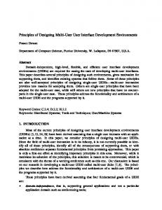
Help display and navigation _-The help tool displays.help frames in a separatewindow as illustrated in Figure 6. The top two panels provide control facilities for the help tool, whereasthe lorv'ertwo contain the page of help information and the primary navigation facilities. The help tool is normally invoked from another tool with relevant context as described above but it can also be invoked by command with suitable parameters to identify the required accesspoint into the help database.In each case, the help tool runs asynchronouslywith other tools, and the user may read context-relatedinformation 9l may browse the help database.If the user only needsa memory jog, the first frame displayed might contain all the information he or she needs. If more information is required the navigation panel is used to traverse the help database. The first frame of information displayedcan be replacedby one showing more detail by the user selecting one of the entries under the title 'Furiher Informaiion'. A lew fr-ameis displayed and the navigation panel is changedto reflect any further breakdown of information available. Links from the current frame to other frames of interest are listed under 'Related Topics' and can be selectedin the same way using the mouse. A history list of help frames visited is maintained under 'Previous Frames', enabling the user to retrace his or trer steps. This helps to avoid the problem, common to man! help systems, of getting lost in the help databaseand being unable to get back to the original entry point. An allied problem is remembering frames of inteiest, and users sometimeshave to note frames to which they may wish to return. To avoid the chore
THE
rffifl
ffirffitfiffit @ @ @ FjEoTnettroo'stePs^
| ffi!
-'
nethod steps - Proilct sel.ctioD analEteps
DareDt fril!
all JsD design iDfonatlon ls In ECLTPSE-V1, rhicl arc regaraledaB belonging held ln oBJECTS a PRoJEcf to a particular P80IECI. Selsction of 'psoudo steP' to uork in is treatld as an lniti.l rethod. of the The si$ steps of tbe fsD rcthod proPer arc: 1 2 3 4 5 6
: : : 3 : :
383
ECLIPSE USER INTERFACE
Further Inforratiotr pro.iect step 6 slep ! O step 4 step 3 step 2 step 1 ielated Iopics control panel
entitY actlon st.P sntity structuro stcP rodcl atrp lnitirl functiot stct stel sYster tirln! steP itplerentatio[
treulous step 1
Frxca
All the aboye STEPS(e!.cluding PS0JECT)have associated ulth thel Prcdefincd diagrils or forns uhich ray be osed to record infornation generated durlng the applic.tion of the JSD r n e t h o d , A d d i t i o n a l l t , . l l S I E P S( i n c l u d l n g PEoJECI) riay have .trt nrrber .f text OBJECTS in uhich the user ray store ant other infornation he lrishes.
Figure6. TheECLIPSEhelptool
of writing down frame references,the help systemprovides a marking facility whereby the user flags (or marks) a frame as being of interest. The system then maintains this list which is displayed in the navigation panel under'Marked Frames'. If the user is browsing, selectand searchfacilities on the help databaseare available through the lower of the two control panels. If the name of a frame is known, this is 'Select'is invoked. That frame is typed into the sign entitled'Frame Reference',and retrieved and displayed. If help is needed on a particular topic, a topic keyword is 'search' is invoked. This comparesthe string against frame typed into the sign, and namesand titles in the databaseand eachone containing the keyword will be recorded. If a single match is found, that frame will be displayed. If more than one match is found, their names and titles will be shown and the user may selectone for display or may mark a number of them for subsequentviewing. The top control panel enablesusersto suppresscertain types of messageif they wish ('Error Level'). 'Print' allows a hard copy of the currently displayed frame to be made and, if necessary,the user may seek help ('Help') on the help system. The comment facility ('Comment') allowsuser remarksto be passedto tool buildersand'Close'closes the window to an icon. THE APPLICATIONS
INTERFACb,
Although various window-based systemscan present comparablevisual interfacesand stylesof interaction to the end-user,the underlying interfacesand mechanismsavailable
384
r. soMMERVTLLr. ET AL.
to applicationsare different. This has the consequencethat applicationsbecomebound to particular window systems. Converting such applicationsto use a different window system may involve major restructuring and modification because of the pervasive nature of managing the user interface and becauseof the lack of standardizationin the software interfaces provided acrosswindow systems. Some standards, such as the Computer Graphics Interface (CGI) exist, but these addressthe problems of managing graphical images.There are not yet any comparable standards for constructing interfaces which use window-based dialogue -anag..r, command interfaces or form-filling interfaces. An application which uses windLws, icons, a mouse and pop-up menus usually has to be written to interface with the facilities supported by one specific workstarion. It is to be hoped that this situation will be rectified in future as a standard such as the X-windows system2ais adopted. Although X-windows has now been acceptedby a number of workstation manufacturers, it was not widely available at the time the ECLIPSE UI was implemented.Furthermore, it is not supportedby PCTE, and our design constraintswere that the systemshould operateusing both Sun workstation and PCTE UI primitives. In ECLIPSE, our objective was to provide a high-level abstractinterface that allows user interfaces to be constructed in such a way that applications using this interface remain independent of the actual I/O devicesbeing used. They should not be bound to the lower level windowing software interface. The end-result, called the Applications Interface,2sis an object-basedsoftware interface through which tools can inieract with the end-user without any knowledge of the style of presentationand without knowing in detail how the end-user interacts with the user interface. It provides an implementation of control panels but is actually of broader utility and has been used in other software products. T!. Applications Interface is implemented by providing a textual description of the interface objects and operations using a description language called FDL (frame description language)and by providing an abstractproceduralinterfacefor applications. Tools interact with the user via this procedural interface which is mapped onto the underlying workstation software. The abstract user interface The basis of the high-level abstract user interface supported by the Applications Interface is a hierarchy of objects representingthe various classesof images-thata tool may need to construct its user interface. There are five levels to the hierarchv. denoted as the screen, windows, frames, panes and fields. At the frame and field levels there are severaldifferent classesof object, as shown in Figure 7. The object at the root of the hierarchy, which cannot have a parent, is called the screen and represents the whole output areaavailableon a workstation. Within the screen,any number of window objects can be defined although only one of these can be completely visible at any one time. This restriction has been imposed in order to enhancethe portability of the user interface. Each window can be subdivided into a set of areascalled frames, of which there are four different classeswhich support different functional uses of their areas: L A graphic frame supports the use of graphical primitives for drawing diagrams and pictures.
THE
. LIGHT .TRIM
ECLIPSE USER INTERFACE
385
. BUTTON
Figure 7. The hierarchy of user inteface objects
2. A TTY frame emulatesa normal characterterminal so that tools which interface to a character terminal can run unchanged on a workstation. 3. A formatted frame supports the control panel mode of tool interaction as discussed earlier. 4. A messageframe provides a textual output area used for all messagesgenerated by tools using this interface. An example of a window containing one of each of the above frame classesis given in Figure 8. This examplealsoshowsthe FDL text which is used to generatethe interface. Only a formatted frame can be subdivided. These subdivisionsare called panes, and consist of a set of fields which a tool wishes to manage as a group. Fields are the lowest level objects in the hierarchy and are generalizationsof the elementsof a control panel through which a tool can interact with an end-user. There
SOMMERVILLE
sage rrame M E S S A GFER A M E .
@ 1:
. l l I N D O l['1l ]
INDolr tlr 1: 1: 1: 1:
. $A,8A) Q,Z)B?,2A
The grey area belou is a G r a p h i cF r a m e .
Example
x
U P D A T E ) / l t l ( A n e x a m p l eU s e r I n t e r f a c e + d e f i n e d i n M M I M SD e s c r i p t i o n L a n g u a g e ) .FRAME [13] ( B, 8)48,5 . M S G _ F R A[M 1 1E] ( 8 , 4 8 ) - > , 6 .TTY_FRAM [ 1E4 ] ( 6 , 8 ) B A , + + .GRAPHIC ltz) ( 7,6?)L5,1?
Figure 8. The frame classes supported by the Applications Interface
are four classesof fields, some of which can have different styles of presentationwhen visible on the user interface: L Input c/ass. This class implements the sign and menu control panel objects. Fields may have a data value entered by the end-user, selected from a list of values generated dynamically or supplied by the tool. The data value may be required to satisfy a syntactic pattern and may be subject to a semanticvalidation procedure; both of these requirements are specified in FDL. 2. Command class. This class implements control panel buttons. When selected,a field of this class causessome action, or command, to be executed. The action may be defined by a procedure within the tool or may be a separateprocess. In the latter casethe processmay be executedsynchronouslyor asynchronouslyand may use the TTY frame as its I/O device. The action, its context and messages, are all specifiedin FDL. 3. Choicec/ass. This classimplements the state selectorcontrol panel object. Fields have a fixed list of possiblevalues, one of which may be chosen by the end-user or the tool. The list of possible values is specified in FDL and is displayed as a pop-up menu. The former style is used to define a state or context value, whereas the latter is used to provide a list of actions from which to chose. 4. Output c/ass. This classimplements control panel lights. Fields of this classmay be used to display fixed test and graphical images on the user interface as commentary to assist the end-user. Each object is defined to representtwo rectangular areaswhich are always constrained within the object's parent in the hierarchy. Each rectangular area has a position and extent relative to its parent and is specified in character units to avoid dependence upon the pixel resolution of any actual workstation. This spatial relationship determines where each object will appear when it becomespart of the visible user image.
THE
ECLIPSE USER INTERFACE
387
The frame description language In order to provide a machine-independentway of describing user interfaces, we have developed a notation, called FDL (frame description language)which is used to set out a textual description of the interface. This description is interpreted at runtime by the interface managementsystem to generatethe actual interface displayed on the user's workstation. The relationshipsbetweenthe tool, the FDL interpreter and the FDL description are shown in Fieure 9.
Figure 9. IrDL and tool interaction
We have deliberately excluded a detailed description of FDL here as it can be considered as the 'object code' driving the applications interface. As discussedlater, neither tools nor interface designersneed have detailed FDL knowledge. FDL is used to define the hierarchy of objects that are required by a tool, together with their relative positions and extents. The positions and sizesof the objects are not available to the tool which uses the FDL, so that the lavout of the obiects mav be changed without affecting the logic and code of the tool. The FDL definition of the objects may also specify the initial values of an object's attributes, such as its visibility and selectability. The text which labels an interface object must be specifiedusing FDL since it may not be defined by the tool. The label part of a field allows that field to be selectedby the end-user typing the label name; if text labels are ambiguous the end-user has to type a sufficient number of charactersto identify the required field uniquely. Field selection using a mouse is controlled entirely by the Applications Interface; the tool has no knowledge of the mechanismsused and is not concernedwith the input devices available to the end-user. The text associatedwith an object may be changed in the FDL without any effect on the tool. The textual values of the choices in a fixed list must be specified using the FDL; each choice has an integer value specifiedwith it in the FDL definition, and this integer is used by tools to referencethat choice. This approach allows the order and textual values of a choice list to be changedwithout affecting the logic or code of the tool. In order to decouplea tool from the FDL specificationof its user interface,each interfaceobject has a name and a set of allowedoperationsassociatedwith it. Objects may be referencedwith this name by the tool, and by operationsto accessits attributes. Thus, tools have a completely procedural interface to an FDL specificationand need not be aware of any detailsof the interfacedescriptionlanguage.
388
I. SOMMERVILLF.
ET AL,
Dynamic control of the user interface At any one time in a system interaction only a subset of all possible interface operationsare valid. If the user attempts an invalid operation, the conventionalresponse is to generatean error messageand allow the user to retry. However, a better approach is to modify the interface dynamically so that only valid operations are presented to the user. The interpretative implementation of FDL makes such dynamic interface modifications possible. As well as allowing the position and extent of user interface objects to be described, FDL allows the dynamic responseof the user interface to end-userand tool operations to be specified. For each type of field the FDL description sets out the actions to be carried out when that field is selectedby the end-user or activated by a tool. For input fields, the FDL description may specify the text of a prompt, a message to assistthe end-userwith data entry and a procedure which may dynamically generate a list of data values from which a choice may be made. For example, say an interface offers an Ada compilation facility which is initiated by picking an 'Ada' button. The FDL description might include a procedure which examines the user's current workspace, selectsthose entities which are of type 'Ada-source' and presents a menu of their names to the user. One of these names is then selectedas the entity to be compiled. The FDL description may also include details of a syntactic pattern which the input value must match, a procedure (or process) which can validate the input value, an error messagewhich is displayed if validation fails and a set of actions to be obeyed when the field's value is successfullyupdated. These actions can include changing the values of the attributes of any of the user interface objects, including the visiblity and selectabilityattributes. Thus, if an operation is invalid at some point in a user interaction, selection of that operation in the interface may be disabled. An example of where this facility is used is in the ECLIPSE MASCOT design editor. Once an entity has been registeredin a design databaseits semanticsmay not be changed, although its position on a design diagram may be modified. Thus, once registered, the operations availableto the editor user are restricted so that destructive operations are simply not presented in the editor operations menu. For command fields the FDL can be used to specify the procedure (or process)that provides the required operation, a messageto be displayed before the command is obeyed, whether the end-user is to confirm the action before the command is obeyed, the context in which to obey the command, an error messageto be displayed if the command fails and a set of actions to be obeved when the command is successful. The user interface generator FDL is a powerful notation for specifying interface objects and actionsbut is a fairly low-level notation, and consequentlyinterface definitions take some time to write and to debug (see the FDL example in Figure 8). This is a particular problem when designing interfaces, as this activity is one which requires a great deal of experiment. Interfaces are generated,tested and then modified during development, and we discovered that writing FDL code was an expensivebusiness. To speed up the processof interface generation, we have developed an interactive interface construction tool.26 Given graphical representationsof the basic interface object classes,the interface builder can simply pick theseand position them as required
THE EcLIPSE USER INTERFAcE
389
on an interface template. There is no need for the user to know the details of the underlying language, indeed, the interface designer need not even know that such a language exists. The tool which we have devised (Figure 10) provides the interface designer with the ability to design ECLIPSE control panels. Basic control panel items (buttons, menus, signs, etc.) may be selectedand positionedon a display. The advantagesoffered by this approach are 1. The designeris given assistancein laying out the interface. 2. End-userscan becomeinvolved in interfacedesign. 3. The time needed to construct new interfacesis reduced dramatically. The difference is perhaps the difference between carrying out computations using a spreadsheet and writing a FORTRAN program to carry out the same computations! CONCLUSIONS The objectives of the user interface project were to construct a portable, consistent, appropriate interface to a project support environment which improved user's pro-
b6Tml fFffi-€-rllE Panol
|
I
ffi
Fleld
Lab6l:
Hme 0lrectorf Act lon I
Fl eld Val us r prmpt
valldatsr m6ssage:
rnfometlon
Enler
ilsssage:
H€lp messager .66d
di.scto.y tot
uith
G€n€'ate a drractory th6
Hma
Datab.s6
descrjpijonr
craphics
lfrager
r-dlr'ctory
nu€ l_istl
burron
Figure 10. The interface creation tool
390
r. soMMERVTLLr. ET AL.
ductivity by speedingup systeminteraction,reducinglearningtime and reducinguser errors. The system which has been built offers a consistent interface (the 'control panel'),includesfacilitiesto help userslearn about the system,and is portableinasmuch as it can be moved to another machine by rehosting the applicationsinterface software. We believe that we have been successfulin achieving our initial objectives but, at the time of writing, we havenot yet carriedout any formal evaluationsof the ECLIPSE UI. However, hooks and tools for evaluation have been provided with the interface and it is intended to start an evaluationprogram in 1988. This will involve theoretical interface modelling, user observationsand questionnairesand analysesof the message logs collected by the system. ACKNOWLEDGEMENTS
The work describedhere was carried out as part of the ECLIPSE project, sponsored by the Alvey Directorate, U.K. Thanks are due to all of the collaboratori in that project, namely Software SciencesLtd., CAP Group Ltd., Learmonth and Burchett Management Systems Ltd., University of Strathclyde, University of Lancaster, and University of Wales, Aberystwyth. REFERENCES l. P. Hitchcock, A. Hall and R. Took,'An overview of the ASPECT architecture',in J. McDermid (ed.), Integrated Prnject Support Enaironments, Peter Peregrinus, London, 1985. 2. R. Took, 'The presenter- a formal design for an autonomous display manager', in I. Sommerville (ed,.), Software Engineeing Enz-sironments,Peter Peregrinus, London, 1986. J. L. A. Price and C. A. Cordova,'Use of mouse buttons',ACM SIGCHI Bulletin,262-266 (1983). T. S. Tullis, 'Designing a menu-based interface to an operating system', ACM SIGCHI Bulletin,
+.
79-84(198s).
5 . A. Marcus,'Screen design for iconic interfaces',ACM SIGCHI'8| Conference,Tutorial 4, 1985. 6 . A. J. Dix, M. D. Harrison, C. Runciman and H. W. Thimbleby, 'Interaction models and the principled design of interactive systems', Prcc. Ist European Conf. on Software Engineeing, Strasbourg, 1987, pp. 137-148. 7. W. Teitleman and L. Masinter, 'The Interlisp programming environment', in D. Barstow, H. E. Shrobe and E. Sandewall (eds), Interactiae Programming Enaironments, McGraw-Hill, New York, 1984. 'A tour through Cedar', IEEE Trans. Software Engineering, SE-11, (3), 285-30?. 1985. 8. W. Teitieman, 9. A. Goldberg, Smalltalh 80: The Language and its Implementation, Addison Wesley, Reading, Mass., 1984. 10. P. Reid and R. Welland, 'Software developmentin view', in I. Sommerville (ed.), Software Engineering Enaironments, Peter Peregrinus, London, 1986. 11. J. Cartmell and A. Alderson, 'The ECLIPSE two-tier database',Proc. lst F)uropeanConf. on Softznare Engineeing, Strasbourg, 1987, pp. 137-l+8. 12. S. Beer, R. Welland and I. Sommerville,'Software design automation in an IPSE', Proc. lst European Conf. on Software Engineering, Strasbourg, 1987, pp. 97-108. 13. R. Pierce,'Ada in the FCLIPSE Project Support Environment', Proc. Int. Ada Conf., Paris, 1985. 'The 14. H. Simpson, MASCOT method', IEEIBCS software Engineeing J., 1, (3), 103-120 (19s6). 15. G. Cutts, Structured SystemsAnalysis and Design Methodology,Paradigm Publishing, London, 1987. 16. A. Albert Alderson, F. Frank Bott and M. Falla, 'An overviewof ECLIPSE', in J. McDermid (ed.), Integrated Pro'ject Support Ent-tironment, Peter Peregrinus, London, 1985. 17. M. F. Bott (ed.), The ECLIPSE Integrated Project Support Enztironment, Peter Peregrinus, London, 1988. 18. I. Campbell,'PCTE proposal for a public common tool interface', in I. Sommerville (ed.), Software Engineeing Entsironments, Peter Peregrin-us, London, 1986. 'The 19. F. Gallo, R. Minot and I. Thomas, object managementsystemof PCTE as a softwareengineering databasemanagement system', ACM SIGPL4N Notices, ZZ, (1), 12-15 (1987).
THE ECLIPSE USER INTERFACE
391
''Guidelines
20. 9j E. Engel and R. E. Granda, for man-display interfaces', Technical Report TR00.2720, IBM, Poughkeepsie,NY. 1975. 'Alphanumeric Zl. M. M. Danchak, displays for the man-process interfac e',Adaances in Instrumentation,
32, (t), 197-2t3(1977).
22. E. S. Cohen, E. T. Smith and L. A. Iverson, 'Constraint-basedtiled windows', IEEE Computer Graphics and Applicatiozs, 6, (5), 35+5 (1986). 23. J. Walker, 'Implementing documentation and help online', Tutoial 9, ACM SIGCHI'8|, San Francisco. 1985. 24. R. W. Scheifler and J. Gettys, 'The X window system', ACM Transactions on Graphics, 5, (2), 79-109 (1986). 25. I. D. Smart, 'A man-machine interface management system for lJnix', Proc. Unifurum t986 Conf., Anaheim, CA, 1986. 26.?. England,'A user flterflce design tool', Proc. Ist European Conf. 9n Software Engineeing, Strasbourg, 1987, pp. 119-126.