The Effect of Boundary Conditions on the Response of Laminated Composites. J. M. WHITNEY. Nonmetallic Materials Division,. Air Force Materials Laboratory,.
The Effect of
Boundary
the
of Laminated
Response
J.
Conditions
on
Composites
M. WHITNEY
Nonmetallic Materials Division, Air Force Materials
Laboratory, Wright-Patterson AFB, Ohio and
Department of Engineering Mechanics, The Ohio State
University,
Columbus, Ohio
(Received January 21, 1970)
The effect of boundary conditions on the bending, vibrations, and buckling of unsymmetrically laminated rectangular plates is investigated. Five sets of boundary conditions corresponding to various clamped and simply-supported edges are treated. The effect of inplane boundary conditions is shown to be a function of fiber orientation within the laminate. Numerical results also show that the effects of bending-extensional coupling can be severe for all the boundary conditions considered. The applicability of the reduced-bendingstiffness approximation is also explored.
INTRODUCTION in various interest in composite materials for wits ~I~I of the laminated analysis aerospace systems, anisotropic plates takes THE INCREASING
use
particular significance. Laminated plate theory [1, 2, 3] displays a coupling phenomenon between inplane extension and transverse bending not found in homogeneous plates. For laminates in which the elastic stiffnesses of the plies are symmetric with respect to the middle plane of the plate, coupling on
vanishes. For highly anisotropic composites, such as boron-epoxy and glass-epoxy, constructed of six layers or less, recent work [3, 4, 5, 6] has shown that coupling can severely effect laminate behavior. In particular, bending deflections are increased while buckling loads and vibration frequencies are reduced compared to results obtained by neglecting coupling. These solutions were obtained for various simple-support boundary conJ. COMPOSITE MATERIALS, Vol. 4
(April 1970),
p. 192
ditions. For certain practical applications, such as the skin of aircraft structures, the composite can be thickness limited making it virtually impossible to use a symmetric laminate. Thus, it seems in order to consider coupling for a wider variety of boundary conditions. This paper investigates bending under uniform transverse load, fundamental frequencies of transverse vibra-
tion, and
buckling under uniform biaxial compression for rectangular crossply angle-ply laminates with various boundary conditions. The major emphasis, however, is on clamped edges. Using the Ritz energy method, Bert and Mayberry [7] considered rigidly clamped boundary conditions in their vibration analysis of nonsymmetric rectangular laminates. Their solution, however, was limited to a three term series in each direction and the degree of convergence of the resulting eigenvalues was not determined. Kicher [8] considered the bending of a nonsymmetric cross-plied elliptic plate with two types of clamped boundaries. To the authors knowledge no other solutions exist for nonsymmetric laminates having clamped boundary conditions. Solutions in the present paper are obtained by the Fourier series method used in Reference [6]. This approach was previously applied to homogeneous isotropic plates by Green [9]. An attempt is also made to provide the structural engineer with a simpler method of analyzing coupled laminates by further investigating the validity of the reduced bending stiffness approxiand
mation
[ 10]. BENDING OF ORTHOTROPIC LAMINATES
Consider a rectangular laminated plate which lies in the region 0 ¿ x G a, 0 G y &dquo; b. Let each layer of the plate be orthotropic with respect to the x-y axes of the plate. For such a laminate the governing equations for static bending under a transverse load q are [3].
where w is the plate deflection, u° and v° in the x and y directions, respectively. Also
and
Qij are
tors
Li
are
are
the reduced stiffness coefficients for defined in the following manner
the
mid-plane displacements
plane
stress
[11]. The opera-
193
with
denoting partial differentiation. boundary condition, designated Cl, is considered a
comma
Transverse loads q are limited to those which double Fourier series
Solutions
to
Equation (1)
are
Equation (6)
can
be
following clamped
represented by
the
of the form
Differentiating u° term-by-term
Since
The
is not valid
with respect to
the
x
yields
edges x 0, x = a, further differentiaccomplished term-by-term [9]. Assuming M,~can be represented by a cosine-sine series, partial integration leads to the ation with
result
194
respect
to
x
cannot
on
be
=
where
A similar constants:
0 W,xx, and w,yy leads cm, dm associated with v y along the edges y
procedure applied
to
to six more sets
=
O,b;
en,
fn
of
associ-
ated with w,xx along x O,a ; and gm, hm associated with w,yy along y = O,b. All other desired derivatives can be obtained through term-by-term differen=
tiation.
appropriate partial derivatives of Equation (5) Equation (1), equating like Fourier terms, and solving the resulting algebraic equations yields Aon, Amn, Bmo, and Bmn in terms of
Substituting Equation (4)
and the
into
the coefficients an, bn, hm. In order that u° vanish on the ...,
edges
x
=
0,
x
=
a, and v° vanish
along
y=O,b
where
In order that the outward normal derivative of
w
vanish
on
the
boundary
Equations ( 8 ) - ( 11 ) yield four sets of simultaneous equations by ranging m and n over even or odd integers. The resulting equations are truncated and solved for the coefficients an, bn, hm. Terms on the right-hand side of these equations and the coefficients of an, bn, hm which are infinite series should be summed separately. Although the results cannot be expressed in closed form without considerable difficulty, sufficient terms can be summed to obtain a desired degree of convergence. The truncated equations are solved ...,
...,
195
digital computer, and convergence is established by increasing the order of the system. Force and moment resultants can be calculated from plate constitutive relations [2]. It should be noted that other boundary conditions can be considered by allowing certain solution vectors to vanish. If an = bn = cm = dm = 0, the following clamped boundary condition, designated C2, is obtained on a
If en
=fn
=
gm = hm
=
0 the
following simple-support boundary condition
is obtained
Finally, if an = bn = en = f n 0, tion, designated SCI, is obtained =
the
following combined boundary
condi-
plate is simply-supported along two opposite edges and clamped along the adjacent edges. For the combined conditions given by Equations ( 16 ) and (17) cm, dm, gm, and hm can be obtained in closed form. i.e. the
BENDING OF ANTI-SYMMETRIC ANGLE-PLY LAMINATES Now consider
laminate in which the principal material axis of the individual layers alternately oriented at ± 9 to the x axis of the plate. For this case the governing equations for static bending are [3] a
are
where
Solutions to
196
Equation (18)
are
assumed
to
be of the form
and
w
is of the
Cl,
as
given by Equations (2)
for
form
Equation (5). For the boundary conditions and (3), we proceed in the same manner as laminates with the result that an and bn are now associated same
as
in
orthotropic with vo along the edges x O,a, while cm and dm are associated with uo The O,b. along remaining coefficients are defined in the same manner as for orthotropic laminates. All other derivatives are obtained through termFor differentiation. the condition Cl, Equations (8) and by-term boundary =
=
(9)
become
Solution vectors
ceding
are
obtained
by
the
= dm
0, the clamped boundary condition,
same
procedure
described in the pre-
section.
If an = bn C3, results
=
cm
=
The simple-support boundary condition given by Equations obtained if en = f= gm = hm = 0. If an = bn = en = f n boundary condition, designated SC2, is obtained
Again
the combined condition,
as
given by Equation (23),
(14) =
0,
can
designated
and a
(15)
is
combined
be obtained
in closed form.
VIBRATIONS AND BUCKLING For vibrations and buckling, inertia terms and membrane force effects be included in the governing equations. Neglecting inplane inertia, only the third relationship in Equations (1) and (18) change. Thus, for ortho-
must
tropic
laminates
and for
we
have [3]
anti-symmetric angle-ply
where p is the
laminates
we
have
density per unit area and the superscript i denotes pre-buckled 197
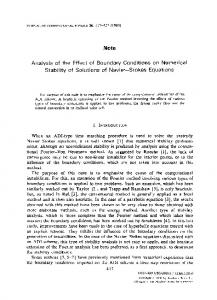
Figure 1. Center deflection wo of a clamped (C1) angleply laminate under uniform transverse load qo.
values. We will consider the
case
of
a
uniform membrane load N, i.e.
where k is
a known constant. Solutions to Equations (24) and
where U, V, and W are
(25)
are
assumed to be of the form
orthotropic laminates and the same procedure as for angle-ply plates. Following the static bending problem leads to four sets of homogeneous equations corresponding to combinations of symmetric and anti-symmetric modes in the x and y directions, respectively. Natural vibration frequencies are obtained by letting N = 0, while static buckling becomes the special case of vanishing M. Proper values of N and w are determined by allowing the determinant of the coefficient matrix in each of the four mode shapes to vanish. The critical buckling load, Ncr corresponds, obviously, to the lowest proper value of N. NUMERICAL RESULTS by Equation (19)
given by Equation (5)
for
for
The effect of coupling is essentially the same for clamped edges as for the various simple-support conditions discussed in References 3, 4, and 6. In particular, the effect depends on the number of layers and the ratio En/Ezz. This is illustrated in Figure 1 where the center deflection wo of a plate with 198
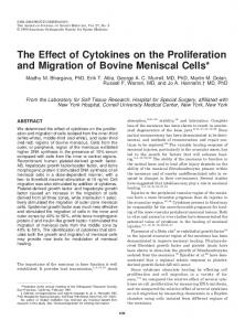
Figure of
a
2.
Buckling
± 45°
under uniform biaxial
compression
clamped (C1) angle-ply plate.
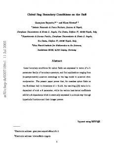
Figure 3. Bending moment Mxo at center of clamped (C1) ± 45° angle-ply plate subjected to the uniform transverse load qo.
boundary conditions under uniform transverse load qo is shown for various angle-ply orientations. Similar results are shown in Figure 2 for the buckling of a -!-45° angle-ply plate, with the same boundary conditions, subjected to uniform biaxial compression. Figure 3 illustrates essentially the same results for the bending moment Mxo at the center of a Cl clamped uniformly loaded plate. The effect of coupling is illustrated in another manner in Figure 4 where the center deflection of a four layer clamped (Cl) symmetric cross-ply composite (fiber directions in each ply at 90°, 0°, 0°, 90° to the x axis of the plate) is compared to a four layer anti-symmetric laminate ( 90°, 0&dquo;, 90°, 0&dquo; ) . Cl
199
Figure 4. Center deflection wo of a clamped (C1) cross-ply plate under uniform transverse load qo.
Figure 5. Center deflectlon wo of a -:t 45° square angleply plate under uniform transverse load with two opposite sides clamped and the adjacent sides simplysupported (SC2).
Obviously coupling increases the center deflection. Figure 5 shows the center deflection for a uniformly loaded anti-symmetric angle-ply plate with the combined boundary conditions SC2. In all these cases €12/~22 = 0.5, v12 = 0.25, while Ell/E22 is indicated on each curve. The homogeneous solutions are obtained by neglecting the B11 coupling terms in the governing equations. It is also interesting to note that the behavior of non-symmetric laminates can be treated as an infinite strip for high values of R. In Figure 6 the center deflection of a two layer ±45° laminate with clamped edges ( Cl ) rapidly approaches the deflection of an infinite strip with clamped supports (desig200
nated CB in the figure ) . For the case of cylindrical bending (infinite strip) the governing equations can be uncoupled [12], yielding a simplified set of three ordinary differential equations. Rapid convergence of the Fourier method is obtained for displacements, vibration frequenqies, and buckling loads. As in the case of most Fourier analyses, bending moments and force resultants require more terms to obtain the desired convergence.
Figure 6. Two layer ::t 45° angle-ply plate with clamped edges (C1) under uniform transverse load qo.
REDUCED BENDING STIFFNESS APPROXIMATION The reduced bending stiffness approximation replaces the bending stiffness Dig of a homogeneous anisotropic plate with reduced bending stiffnesses where D3
This
allows a nonsymmetric laminate to be analyzed as a homogeneous plate. Reissner and Stavsky [1] originally suggested this approach which has been further pursued by Ashton [10]. For the simply-supported boundary conditions discussed in Reference 6, the reduced bending stiffness approximation gave excellent agreement with nonsymmetric cross-ply bending solutions. For certain anti-symmetric angleply orientations, however, the degree of agreement depended on the type of simple-support boundary condition. Similar observations are made for the clamped boundary conditions considered in the present paper. In particular, Table 1 shows excellent agreement between the clamped conditions Cl, C2, and the reduced bending stiffness approximation ( RBS ) for the bending, vibrations, and buckling of nonsymmetric cross-ply plates, while the degree of agreement in Table 2 for anti-symmetric angle-ply plates is a function of 6. For certain angle-ply orientations there is a relatively large discrepancy between the clamped conditions Cl, C3, and the RBS approximation. It is interesting to note in Table 2 that the rigidly clamped condition Cl reduces the stiffness of angle-ply plates compared to the less rigid clamp C3, i.e., bending deflections are larger, fundamental vibration frequencies are less, and critical buckling loads are less for the Cl conditions. All values of w in Tables 1 and 2 correspond to fundamental vibration frequencies.
approximation
201
Table 1. Effect of
boundary conditions for a 2 layer cross-ply plate
Table 2. Effect of
boundary conditions
202
for
a
2
layer angle-ply plate
CONCLUSIONS It appears that the effect of
bending-extensional coupling on laminate essentially independent of boundary conditions. The effect is primarily a function of the ratio Ell/E22 of the individual plies, and the number of layers in the laminate. In all cases, bending-extensional coupling reduces the effective plate stiffness, i.e., bending deflections are increased, while fundamental vibration frequencies and critical buckling loads are decreased compared to equivalent homogeneous plates. For certain orientations of anti-symmetric angle-ply plates, membrane boundary conditions can significantly influence plate response. As a result, the reduced bending stiffness approximation does not give acceptable agreement with coupled laminate solutions for these orientation. Unlike the case of simple-supports discussed in Reference 6, the RBS method does not agree with either of the clamped boundary conditions presently considered for the angle-ply orientations which are sensitive to membrane boundary conditions. Further studies of the effect of membrane boundary conditions on the response of anti-symmetric angle-ply laminates would be useful.
response is
ACKNOWLEDGEMENT The author wishes to
acknowledge Wright-Patterson Air computer programming.
Systems Division, in
Mr. E. H. Guthrie of the Aeronautical Force Base for his valuable contribution
REFERENCES 1. E. Reissner and Y. Stavsky, "Bending and Stretching of Certain Types of Heterogeneous Aeolotropic Elastic Plates," J. Applied Mechanics, Vol. 28 (1961), p. 402. 2. Y. Stavsky, "Bending and Stretching of Laminated Aeolotropic Plates," Proc. Am. Soc. Civil Engineers . Div . Eng. Mech J .), Vol. 87, EM6 (1961), p. 31. : ( 3. J. M. Whitney and A. W. Leissa, "Analysis of Heterogeneous Anisotropic Plates," J. Applied Mechanics, Vol. 36 (1969), p. 261. 4. J. M. Whitney, "Bending-Extensional Coupling in Laminated Plates Under Transverse Loading," J. Composite Materials, Vol. 3 (1969), p. 20. 5. J. M. Whitney, "Shear Buckling of Unsymmetrical Cross-Ply Plates," J. Composite Materials, Vol. 3 (1969), p. 359. 6. J. M. Whitney and A. W. Leissa, "Analysis of a Simply-Supported Laminated Anisotropic Rectangular Plate," AIAA Journal, Vol. 8 (1970), p. 28. 7. C. W. Bert and B. L. Mayberry, "Free Vibrations of Unsymmetrically Laminated Anisotropic Plate with Clamped Edges," J. Composite Materials, Vol. 3 (1969), p. 282. 8. T. P. Kicher, "The Analysis of Unbalanced Cross-Plied Elliptic Plates Under Uniform Pressure," J. Composite Materials, Vol. 3 (1969), p. 424. 9. A. E. Green, "Double Fourier Series and Boundary Value Problems," Cambridge Philosophical Society, Proc., Vol. 40 (1944), p. 222. 10. J. E. Ashton, "Approximate Solutions for Unsymmetrically Laminated Plates," J. Composite Materials, Vol. 3 (1969), p. 189. 11. S. W. Tsai and N. J. Pagano, "Invariant Properties of Composite Materials," Composite Materials Workshop, edited by S. W. Tsai, J. C. Halpin, and N. J. Pagano, Technomic Publishing Co., Inc. (1968). . Com12. J. M. Whitney, "Cylindrical Bending of Unsymmetrically Laminated Plates," J posite Materials, Vol. 3 (1969), p. 715.
203