Solar Energy Materials and Solar Cells 176 (2018) 119–133
Contents lists available at ScienceDirect
Solar Energy Materials and Solar Cells journal homepage: www.elsevier.com/locate/solmat
The effect of incidence angle on the reflectance of solar mirrors a,⁎
b
a
T c
Florian Sutter , Marco Montecchi , Haymo von Dahlen , Aránzazu Fernández-García , Marc Rögera a b c
DLR German Aerospace Center, Institute of Solar Research, Plataforma Solar de Almeria, Ctra. Senés Km. 4, P.O.Box 44, 04200 Tabernas, Almería, Spain ENEA C.R. Casaccia, Departmet of Energy Technologies, Via Anguillarese, 301, 00123 S. Maria di Galeria, Roma, Italy CIEMAT, Plataforma Solar de Almeria, Ctra. Senés Km. 4, P.O.Box 22, 04200 Tabernas, Almería, Spain
A R T I C L E I N F O
A B S T R A C T
Keywords: Reflectance Incidence angle Solar reflector Solar weighting Spectral reflectometer
Solar reflectors for Concentrating Solar Technologies require a high reflectance in the terrestrial solar spectrum (280–4000 nm). Besides the wavelength, the reflectance of solar mirror materials is also dependent on the incidence angle of the incoming sunlight. The commonly used measurement equipment measures the reflectance at fixed near-normal incidence angles, typically between 8° and 15°. In this work, the annual incidence angle frequency distribution has been calculated for a LS3/Eurotrough-type parabolic-trough collector located at different sites, and for the heliostat field of the solar tower system CESA-1 located at the Plataforma Solar de Almería in Tabernas, southern Spain. It was found that the most frequent incidence angles registered in the solar field are quite higher than the ones at which reflectance is measured with state of the art instruments, obtaining mean incidence angles in the range of 28–35° depending on the type and location of the solar field. A methodology to predict the off-normal reflectance of silvered-glass mirrors based on near-normal reflectance and transmittance measurements of the uncoated glass is presented. The complex refractive index of 2, 4 and 5 mm thick solar glass and the deposited silver was determined and used to model the solar weighted reflectance of silvered-glass mirrors at different incidence angles. The model was compared to experimental measurements. For this purpose, the Spectral Specular Reflectometer (S2R) has been improved and updated with a polarizer crystal to measure reflectance at perpendicular (s-pol) and parallel (p-pol) polarizations up to incidence angles of θ = 70°. Eight solar mirror materials (three silvered-glass mirrors of different glass thicknesses, two anti-soiling coated glass mirrors, two enhanced aluminum reflectors and a silvered polymer film) have been measured over a broad range of incidence angles and the results have been weighted with the annual incidence angle frequency distribution. The obtained incidence angle-weighted reflectance is a suited parameter to compare the efficiency of solar mirror materials taking into account their use in a specific collector type and location.
1. Introduction In Concentrating Solar Technologies (CST), solar light is concentrated on a focal point or a focal line by using 2-axis or 1-axis tracking mirrors. A receiver, located in the focal point or line transforms the collected solar radiation either directly to electricity with concentrating photovoltaic (CPV) systems [1], to heat which can be used in a heat engine to produce electricity with concentrating solar power (CSP) systems [2] or for chemical [3] or thermal processes in industrial applications [4]. The reflectance, ρ, is defined as the ratio of the radiant flux reflected from a surface to that of the incident radiation [5]. The reflectance of tracking solar mirrors, ρλ,φ(λ,θ,φ,Ts), is dependent on the following four parameters: the wavelength λ and the incidence angle θ of the incident ⁎
light, the acceptance angle φ of the receiver, which defines the admissible angular area around the perfect specular reflection, and the surface temperature Ts [6,7]. The relevant wavelength range for solar reflectors is the terrestrial solar spectrum λ = [280, 4000] nm. A representative mean value of all ρ in this range is obtained by performing a solar weighting with a standard solar spectrum (e.g. according to [8] (direct irradiance) for air mass AM 1.5 or [9]). Because the far-NIR and UV ranges have a low impact and it is practically more convenient for the measurement equipment, the relevant measurement range for reflectance evaluation can be resized to λ = [320, 2500] nm. The absolute weight of solar radiation in the wavelength intervals [280, 320] and [2500, 4000] nm is less than 1% in total. For the temperature range achieved during normal operation of
Corresponding author. E-mail address:
[email protected] (F. Sutter).
https://doi.org/10.1016/j.solmat.2017.11.029 Received 25 September 2017; Received in revised form 14 November 2017; Accepted 16 November 2017 0927-0248/ © 2017 Elsevier B.V. All rights reserved.
Solar Energy Materials and Solar Cells 176 (2018) 119–133
F. Sutter et al.
reflectance ρs,h([320, 2500]nm,8°,h) of front face of glass slab [-] Ts surface temperature [°C] wcol aperture width of PTC [m] y(x) parabolic mirror shape [m] α absorption coefficient of the solar glass [nm−1] αS elevation angle of the sun [−90°; 90°] [°] β incidence angle after refraction [°] γS,geo azimut angle of the sun [0°; 360°] [°] ε1, ε2 dielectric constants to describe the refractive index and extinction coefficient [-] θ incidence angle [°] θgeom incidence angle of a PTC due to parabolic 2D-geometry [°] θsun incidence angle between collector normal and sun [°] λ wavelength [nm] ρ reflectance [-] ρair|glass reflectance at the interface between air and glass [-] ρair|glass|silver reflectance of the Air|Glass|Silver model [-] ρglass|air reflectance at the interface between glass and air [-] ρglass|silver reflectance at the interface between glass and silver [-] ρi see ρi(λ, T, L, φ) [-] ρi(λ, T, L, φ) incidence angle weighted specular reflectance for collector type T at a given location L [-] ρnon-pol reflectance of non-polarized light [-] ρp-pol reflectance of parallel polarized light [-] ρs,h solar-weighted hemispherical reflectance at θ=8° and [320,2500]nm [-] ρs,h([λ1, λ2],θ,h) solar-weighted hemispherical reflectance [-] ρs,φ solar-weighted specular reflectance at θ=8° and [320,2500]nm [-] ρs,φ([λ1, λ2],θ,φ) solar-weighted specular reflectance [-] ρs-pol reflectance of perpendicular polarized light [-] ρλ spectral reflectance [-] ρλ,h(λ,θ,h) spectral hemispherical reflectance [-] τ see τs,h [-] τ(λ,θ,h) spectral hemispherical transmittance [-] τf transmittance τ([320, 2500]nm,8°,h) of front face of glass slab [-] τs,h solar-weighted hemispherical transmittance at θ=8° and [320,2500 nm] [-] φ acceptance angle [mrad]
Nomenclature CESA-1 CPV CSP CST DNI EMA ENEA NIR NIST PSA PTC S2R ST TIS URA B1 B2 B3 C1 C2 C3 Eλ f h kg kg,s ks ns n1 n2 ng ng,s ns θθ R
Rf
central receiver power tower at PSA Concentrating Photovoltaics Concentrating Solar Power Concentrating Solar Technologies Direct Normal Irradiance Equivalent Model Algorithm Agenzia nazionale per le nuove tecnologie, l'energia e lo sviluppo economico sostenibile Near infrared National Institute of Standards and Technology Plataforma Solar de Almería, located in Tabernas, Spain parabolic–trough collector Spectral Specular Reflectance Accessory solar tower Total Integrated Scattering Universal Reflectance Accessory constant of Sellmeier's equation [-] constant of Sellmeier's equation [-] constant of Sellmeier's equation [-] constant of Sellmeier's equation [μm²] constant of Sellmeier's equation [μm²] constant of Sellmeier's equation [μm²] Spectral irradiance of standard solar spectrum [W/m³] Focal length of PTC [m] thickness of glass slab [mm] extinction coefficient of glass [-] solar weighted extinction coefficient of glass in the range [320,2500]nm [-] extinction coefficient of silver [-] complex refractive index of silver [-] refractive index of air [-] refractive index of medium 2 [-] refractive index of glass [-] solar-weighted refractive index of glass in the range 3202500 nm [-] refractive index of silver [-] relative annual incidence angle distribution (whole year) [-] reflectance ρs,h([320, 2500]nm,8°,h) of glass slab [-]
primary solar mirrors in the field, the influence of Ts on ρ is not significant and may be neglected. Therefore, in the rest of this work, this parameter is omitted and the nomenclature used for reflectance is ρλ,φ(λ, θ, φ). The indices λ,φ denote specular monochromatic
reflectance. The indices s,h denote solar weighted hemispherical reflectance in the wavelength range [320, 2500]nm. For CST the specular reflectance plays a significant role, since scattered light outside the acceptance angle cone is lost to the energy
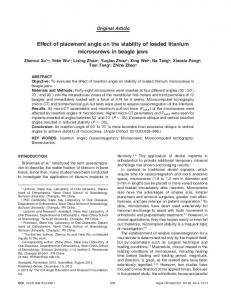
Fig. 1. a) Distance of closest and furthermost heliostat from the receiver in the ST plant of Ivanpah, b) dimensions used to compute the acceptance angle φ.
120
Solar Energy Materials and Solar Cells 176 (2018) 119–133
F. Sutter et al.
conversion process. The acceptance angle φ is defined by the geometric dimensions of the concentrator and the absorber type employed. For the typical parabolic trough collectors (PTC), the selected φ of reflectance measurements is usually set to 12.5 mrad [10,11]. For solar tower (ST) systems, the φ varies with the distance of the heliostat to the receiver and the receiver dimension. This is illustrated in Fig. 1, where the φ for the closest and furthermost heliostat has been computed for the Ivanpah solar tower plant located in California, USA. The used dimensions are approximate values based on technical data about the plant shown in [12]. The results show that the acceptance angles are in the range of φ = [6,46] mrad. Taking into account sunshape, mirror slope deviations and tracking errors, the mirror materials for solar tower systems should be evaluated at even smaller acceptance angles than the 6 mrad for the furthermost heliostat to determine the amount of energy lost due to scattering of the material. However, no measurement device exists to the present state of the art that is capable to measure the reflectance at these acceptance angle ranges covering the whole solar wavelength range. Existing reflectometers with acceptance angles suited for CST applications usually measure monochromatically [11,13–19]. On the other hand, spectrophotometers are able to measure at the desired wavelength range but at much larger acceptance angles. For instance, spectrophotometers from Perkin Elmer use accessories such as the “Integrating Sphere Accessory” for hemispherical measurements or the “Universal Reflectance Accessory” (URA), in which the acceptance angle has been estimated to be at least around φ = 90 mrad, based on geometric considerations. Up to now, not much research regarding the detailed effect of different incidence angles θ on the overall reflected intensity of a solar collector field has been conducted, although the theory to describe the reflectance was developed by Fresnel in the 19th century. One approach commonly adopted in some CSP technologies to solve the lack of knowledge about the influence of the θ on the different parameters that integrate the efficiency of the system is to mathematically group this effect into a unique factor, named incidence angle modifier [20]. This parameter is typically obtained experimentally and is useful when the goal is to figure out the influence of θ in the overall efficiency of the solar collector. However, it does not provide any information about the impact of θ on a component or material level, such as ρ, and the equipment to properly measure them. This paper evaluates the effect of θ of different solar reflector materials on the efficiency of solar concentrating systems and proposes a suitable parameter to describe this effect.
systems were performed using MATLAB and STRAL. Michalsky's equations [21] were evaluated in MATLAB to determine the sun position. The required input parameters are: time, longitude, latitude and altitude; the output are the sun-angles elevation αS, and azimut γS,geo. The Michalsky formula was evaluated every 2 min until completing the data set of one year. Shading due to clouds was not considered. 2.1.1. Annual incidence angle distribution of parabolic trough mirrors The calculation for a north-south oriented PTC is entirely realized in MATLAB for the locations PSA (Plataforma Solar de Almeria located in Tabernas, Spain), Ouarzazate (Morocco), Aswan (Egypt) and the equator. The LS-3/Eurotrough geometry was used with the following input parameters: focal length f = 1.71 m and aperture width wcol = 5.76 m. Since the geometry is symmetric, only one half was considered. As spacial input discretization, 1130 points in x direction were evaluated, with x ∈ [0, 2.88] m. Therefore we obtain 1129 segments with the discretization step Δx = 2.88 m/1129 = 2.55 mm. The incidence angle distribution of a solar field nθ (t ) , is obtained by calculating the appearing θ on each of the 1129 collector points for each time step of 2 min. The amount nθ (t ) of the appearing incidence angles are summed up over the timeframe of one year and divided by its maximum value, so that a relative annual incidence angle distribution nθ is obtained. The cross section of a PTC is formed by a parabola. In the coordinate system depicted in Fig. 2a, the parabolic collector shape y(x) is dependent on f as follows:
y (x ) =
1 x² 4f
(1)
In the cross-section plane of a PTC, the normal component of the incident solar light is always paralell to the collector normal (see y-axis in Fig. 2a) thanks to the tracking system. Due to the 2-dimensional parabolic shape of the concentrator, the angle formed by the incident beams and the normal of a local surface point varies along the parabola. This 2-dimensional incidence angle due to the given collector geometry θgeom can be written as (for θgeom ≤ 45°):
θgeom (x ) =
⎛ ⎞ x x 1 1 ⎞ arctan ⎜⎛ arctan ⎜ ⎟ = ⎟ 1 ⎜ − f y x 2 ( ) 2 f − 4f x ² ⎟ ⎝ ⎠ ⎝ ⎠
(2)
Fig. 2b shows the parabolic shape and the corresponding θgeom. Normal incidence on the collector as depicted in Fig. 2a only happens at reduced time frames over the course of a year. The single axis tracking of the PTC follows the sun's elevation but not its azimuth angle, shifting the overall incidence angle θ on the collector towards higher values. θ was calculated using the time-independent angles θgeom and the angle between the normal of the collector aperture plane and the sun θsun:
2. Annual incidence angle distribution of CSP collector fields 2.1. Methodology to compute the annual incidence angle distribution
θ = arccos (cosθgeom ∙cosθsun )
Simulations of yearly θ at different locations and for different CSP
(3)
Fig. 2. a) Visualization of θgeom, b) half of LS-3/Eurotrough geometry with f = 1.71 m, wcol = 5.76 m and incidence angle θgeom(x) at the special case of normal incidence on the collector.
121
Solar Energy Materials and Solar Cells 176 (2018) 119–133
F. Sutter et al.
The angle θsun and its cosine represent the cosine-loss of the collector and depend on the sun's position [22]:
cosθsun =
1−cos 2 αs ∙cos ²γs, geo
(4)
Eq. (4) is only valid for αs ≥ 0° (daytime) and north-south orientation. For east-west orientation, cos ²γs, geo must be replaced by sin²γs, geo in Eq. (4). 2.1.2. Annual incidence angle distribution of solar tower mirrors For the tower technology, only the location Tabernas (Spain) is investigated. The incidence angles for the 269 heliostats of the CESA-1 solar tower heliostat field (see Fig. 3) at PSA are determined using the raytracing program STRAL [23]. Shading and blocking due to the field layout were not considered. For every time step, except for those where αS < 0° (night time), the incidence angle θ was calculated and discretized rounding half up to the nearest integer (0°, 1°, 2°, …).
Fig. 4. Relative annual incidence angle distribution nθ on mirror materials employed in parabolic trough collectors at PSA (Spain), Ouarzazate (Morocco), Aswan (Egypt) and the equator and in the heliostat field of the CESA-1 solar tower at PSA (Spain).
2.2. Results
θ =
distributions shown in Fig. 4 are calculated using: θ
Fig. 4 shows the relative annual incidence angle distribution nθ at different locations. The resulting distribution for PTC is partially linearalike (overlay of parabolic geometry and hyperbolic sun influence) and partially hyperbolic, where the sun position has the higher influence than the geometry. The shape of the PSA heliostat field reminds one of a Weibull distribution. For the north-south PTC, the most frequent appearing incidence angles are θ = 39°, which is the angle on the collector rim at normal incidence. For the equator, a second and higher maximum exists at θ = 23°, the angle the earth axes is tilted. The incidence angle distribution is shifted towards higher values with increasing latitude. For the PSA CESA-1 heliostat field, the incidence angles are generally lower in comparison to the PTC at the same location. However, the maximum appearing incidence angle for the heliostat field (θ = 80°) is higher than for the PTC (θ = 68°). The sharp edges in the annual incidence angle distribution curves are due to complex interactions of collector geometry and location. Easier cases to retrace are shown in Fig. 5, where the θ curves are plotted for the 21st of March at the equator, and a summer and winter day at the PSA for a north-south oriented PTC. The left part of the figure shows the tracked incidence angle on three spots on the collector (outermost point x = 2.88 m, middle point x = 1.44 m, and parabola vertex x = 0 m, compare Fig. 2) over the course of a day. On the 21st of March, the PTC located at the equator receives normal incidence over the course of the entire day, for this reason the local θ remain constant. The frequency distribution over this day has a parabolic shape and presents a maximum at θ = 39° (as result of the discretization described in Section 2.1.1). On a summer day at PSA, normal incidence on the collector happens twice a day, while as in the winter it does not happen at all. The corresponding frequency distribution plots show sharp edges, which are being transferred to the annual distributions curves shown in Fig. 5. The arithmetic mean value θ of the annual incidence angle
θ∙nθ ∑θmax =0 θ
nθ ∑θmax =0
(5)
Table 1 shows the computed θ and the maximum appearing incidence angle θmax per location and collector type. As can be seen in Table 1, for the north-south oriented PTC, the mean and maximum incidence angle θ and θmax values increase with the latitude. Since only one non-commercial heliostat field has been computed, no general assumptions shall be made regarding the annual incidence angle distribution for solar towers. Commercial heliostat fields are often being built as round field on both sides of the tower and thus lead to higher incidence angles. An important result of this analysis is that the incidence angles at which reflectance is measured with state of the art instruments (8° to 15°) are not representative for the incidence angles appearing during operation. For this reason the angular dependency of the reflector material needs to be known in order to properly evaluate its efficiency. The following section presents a simple way to predict the off-normal reflectance of silvered-glass mirrors based on near-normal hemispherical reflectance and transmittance measurements. 3. Prediction of off-normal reflectance based on hemispherical reflectance and transmittance measurement The off-normal reflectance of commercial silvered-glass reflectors from the company of Flabeg FE of different glass-thicknesses (2, 4, and 5 mm) was evaluated following the four steps described below: 3.1. Measurement of the near-normal hemispherical reflectance of the silvered-glass mirrors The reflectance of 2, 4 and 5 mm solar mirrors was measured using the PerkinElmer Lambda 1050 spectrophotometer in combination with a 150 mm integrating sphere. The resulting reflectance spectra are
Fig. 3. Simulated (left) and actual (right) CESA-1 heliostat field at PSA (Spain) with 269 heliostats.
122
Solar Energy Materials and Solar Cells 176 (2018) 119–133
F. Sutter et al.
Fig. 5. left: incidence angle θ on three collector spots (in the vertex ×0 = 0, middle xmiddle = 1.44 m and outermost point of the parabola xouter = 2.88 m) over the course of one day of a north south oriented PTC, right: daily incidence angle frequency distribution (computed for 1130 collector spots).
3.2. Determination of the refractive index ng and extinction coefficient kg of the solar glass
Table 1 Maximum θmax and mean annual incidence angle θ according to location and collector type. Location
Latitude
θ [°]
θmax [°]
Equator (PTC) Aswan (PTC) Ouarzazate (PTC) PSA (PTC) PSA (ST)
0°0‘ 24°05‘ 30°56‘ 37°05‘ 37°05‘
27.8 30.8 32.8 34.8 29.8
45 59 64 68 80
After all layers were successfully removed from the mirror, the refractive index ng was determined for the glass slabs at the same spots where the reflectance was measured of the former mirror. In order to determine ng, the reflectance ρλ,h([320,2500]nm, 8°, h) and transmittance τ([320,2500]nm, 8°, h) of the glass slabs were measured using the PerkinElmer Lambda 1050 spectrophotometer. For the transmittance measurement, the sample was placed 10 cm away from the sphere entry port to avoid back reflection into the sphere (see Fig. 7a). The solar glass is highly specular and the measured transmittance value equals the hemispherical transmittance. Placing the sample away from the sphere has the benefit that the back reflection from the sample into the sphere is kept to a minimum, reducing in such way a systematic error from the transmittance measurement. The measured reflectance of the glass slab R consists of multiple contributions from the front and back side (see Fig. 7b). If R and τ are known, the single face reflectance of the front side Rf can be computed
plotted in Fig. 6. The legend of the graphs also shows the computed solar weighted hemispherical reflectance at the incidence angle of θ = 8°. The reflectance spectra show a low reflectance in the UV range due to absorption processes in glass and silver. In the visible and near infrared range, absorption is mainly influenced by glass thickness. After having performed these measurements, the mirror samples were placed over night in a mixture of nitric and sulfuric acid to dissolve metal and paint layers, obtaining the bare slabs of the solar glass. 123
Solar Energy Materials and Solar Cells 176 (2018) 119–133
F. Sutter et al.
Fig. 6. Measured hemispherical reflectance of three silvered-glass mirrors with different glass thicknesses. a) scale 0–1, b) 0.75–1.
measurement. The data from 350 to 2500 nm of ng was fitted using Sellmeier's equation (see Eq. (9)), which allowed extrapolating the refractive index in the range from 320 to 350 nm.
according to [24]:
Rf =
2+τ 2 − (1−R)2 −
[2+τ 2 − (1−R)2]2 −4R (2−R) 2(2−R)
(6)
ng2 (λ ) = 1 +
The measured transmittance and reflectance spectra are shown in Fig. 8. The measured R and τ and the computed Rf were used to calculate the refractive index ng and the extinction coefficient kg of the three different glass slabs using the equations described by [24]:
ng =
kg =
1+Rf 1−Rf
+
4Rf (1−Rf
Rf τ ⎞ λ ln ⎜⎛ ⎟ 4πh ⎝ R − Rf ⎠
)2
λ ⎞2 2 ⎛ Rf τ ⎞ −⎛ ln ⎜ ⎟ ⎝ 4πh ⎠ ⎝ R − Rf ⎠
B1 λ2 B λ2 B λ2 + 2 2 + 2 3 − C1 λ − C2 λ − C3
λ2
(9)
The six constants of the Sellmeier equation were determined by least square fit to the measured data using the Levenberg-Marquardt algorithm. The resulting constants used to describe the measured data are shown in Table 2. The obtained curves of ng according to Sellmeier's equation were used to compute the smoothened extinction coefficient kg of the solar glass by solving Eq. (10) [24] for kg, in which τ is known from measurement.
(7)
(8)
τ f2exp(−αh)
τ=
where h denotes the thickness of the glass slab. The resulting spectral refractive index and extinction coefficient are shown as dots in 5 nm steps in Figs. 9 and 10. As can be seen in Fig. 9, the measured data in the UV-range (from 320 to 350 nm) shows an atypical decay, not observed in literature. It is believed that the low values of the refractive index in the UV range arise due to the increased measurement uncertainty of the spectrophotometer at these wavelengths, albeit an aluminum reference mirror was used to increase the UV intensity during the reference
1 − Rf2exp(−2αh)
(10)
where
Rf =
τf =
ng − ik g −1
2
ng − ik g +1
(11)
4ng ng − ik g +1 2
(12)
The absorption coefficient α of the solar glass is:
Fig. 7. a) Position of the glass slab in the PerkinElmer Lambda 1050 spectrophotometer for the transmittance measurement. b) Schematic of the reflectance and transmittance at the glass slab.
124
Solar Energy Materials and Solar Cells 176 (2018) 119–133
F. Sutter et al.
Fig. 8. Measurements of the solar glass slabs of 2, 4 and 5 mm thickness. a) Transmittance τ at 8° incidence. b) Total reflectance R and computed single face reflectance Rf.
α=
4πk g (13)
λ
In addition, negative kg data was corrected and set to zero, because a negative extinction coefficient is physically not possible. Negative kg values arise due to the uncertainty of the reflectance and transmittance measurements of the glass slabs performed in the spectrophotometer. Fig. 10 shows the measured kg data of the three glass slabs according to Eq. (8) (dots) and the corrected values according to Eqs. (10)–(13) (lines). The legend of the graphs in Figs. 9 and 10 also display the solar weighted refractive index and extinction coefficients ng,s and kg,s, which give a useful average value over the solar wavelength range of [320, 2500]nm. 3.3. Determination of the complex refractive index ns of silver
Fig. 9. a) Refractive index ng of solar glass computed according to Eq. (7) (dots) and fit (line) computed according to Eq. (9).
The refractive index of silver is a complex number: (14)
ns = ns + iks
The real part ns of the complex refractive index of silver was obtained from literature data. The reported data from the Brendel-Borman model [25] and Palik [26] are in good agreement (see Fig. 11a). For further analysis, the data from Brendel-Borman model was used. The complex part of the refractive index of silver ks (extinction coefficient of silver) is computed by solving the Fresnel equation of the Air|Glass|Silver model shown in Fig. 11b. Fresnel found that the reflectance at the interface of two media (e.g. of refractive index n1 and n2) can be described by the following equations for parallel (p) and perpendicular (s) polarized light, ρp-pol and ρspol, respectively [27]:
Fig. 10. Extinction coefficient kg of solar glass computed according to Eq. (8) (dots) and fit (line) computed according to Eqs. (10)–(13).
ρp − pol =
n2cos (θ) − n1cos (β ) n2cos (θ) + n1cos (β )
ρs − pol =
n1cos (θ) − n2cos (β ) n1cos (θ) + n2cos (β )
2
(15) 2
(16)
where β can be calculated according to Snell's law: Table 2 Determined constants of Sellmeier's equation.
n β = arcsin ⎛ 1 sin (θ) ⎞ ⎠ ⎝ n2 ⎜
Glass thickness
B1 [-]
B2 [-]
B3 [-]
C1 [μm²]
C2 [μm²]
C3 [μm²]
2 mm 4 mm 5 mm
1.0790 1.1513 1.0812
0.3026 0.2609 0.3339
0.1004 0.5949 1.0098
0.0141 8.8551 e-08 0.0118
0.0142 0.0382 0.0086
19.3784 60.2730 92.5030
⎟
(17)
The overall reflectance of non-polarized light, ρnon-pol, yields:
ρnon − pol =
1 (ρ + ρn − pol ) 2 p − pol
(18)
As shown in Fig. 11b, the overall reflected energy of a silvered glass mirror is composed of several rays, which all need to be taken into 125
Solar Energy Materials and Solar Cells 176 (2018) 119–133
F. Sutter et al.
Fig. 11. a) real part of the refractive index ns of silver (literature data). b) Air|Glass|Silver model considered for the Fresnel equations.
with literature data from the Brendel Bormann model [25] for comparison.
account. For the Air|Glass|Silver model, the reflectance at the air-glass interface ρAir Glass was calculated setting n1 = 1.000292 (air) and the determined values of the corresponding solar glass of the Sellmeier fit (as described in Section 3.2) as n2 = ng + i kg in Eqs. (15)–(18). At the glass-silver interface, ρGlass Silver is calculated using Eqs. (15)–(18) with n1 = ng + i kg (again the solar glass values of the Sellmeier fit from Section 3.2) and n2 = ns + i ks, which contains the unknown variable ks (ns is known from literature data according to the Brendel-Borman model [25]). The overall reflectance at the Air|Glass|Silver model depicted in Fig. 11b is:
ρAir
Glass Silver
= ρAir
Glass
+ (1−ρAir
Air )
= ρAir
+ (1−ρAir
Glass ) ∙ρGlass Silver
Air ) ∙ρGlass Air
⎛ 2αh ⎟⎞ ∙ρ Glass ⎝ cosβ ⎠ ⎛ 2αh ⎟⎞+… Silver ∙exp ⎜ − ⎝ cosβ ⎠ Silver ∙exp ⎜ −
Glass
+ (1−ρAir
Glass ) ∙ρGlass Silver
Air ) ∙ρGlass Air ∙ρGlass Silver
2αh ⎞ ∙exp ⎜⎛− ⎟ + (1−ρ Air ⎝ cosβ ⎠ 2αh ⎞ ∙exp ⎜⎛− ⎟ ∙ (1−ρ Glass ⎝ cosβ ⎠
∙ρGlass
Once the refractive indices of the solar glass and the deposited silver have been determined, one can use the Fresnel Eqs. (15)–(18) and Eq. (21) to compute the reflectance of the silvered-glass mirrors at different incidence angles. Fig. 13a shows the computed spectra at θ = 0°, 80° and 89° compared to the measured data at 8° of the 2 mm mirror. Perfect agreement between the measured data and the computed normal incidence can be seen, as expected since the measured reflectance was used to determine ks. With increasing incidence angle, the spectra approach 100%, due to the growing reflectance at the glass surface, which is in accordance to physical theory. Fig. 13b shows the obtained solar weighted reflectance ρs,h([320,2500 nm],θ,h) at different polarizations (s-pol, p-pol and nonpol) plotted over the incidence angle for the 2, 4 and 5 mm glass reflectors. It can be seen that the reflectance remains independent from the incidence angle up to θ = 50°, afterwards it starts to increase slightly and starting around 80° a steep increase towards 100% can be appreciated. It can also be seen that the reflectance decreases with increasing glass thickness, as a result of the absorption in the glass.
Glass ) ∙ρGlass Silver
2αh ⎞ ∙exp ⎜⎛− ⎟ ∙ (1−ρ Glass ⎝ cosβ ⎠ 2αh ⎞ ∙exp ⎜⎛− ⎟ ∙ (1−ρ Glass β⎠ cos ⎝
∙ρGlass
3.4. Computation of the reflectance of the Air|Glass|Silver model for different incidence angles
Glass ) ∙ρGlass
Air
4. Measurement of off-normal reflectance
⎛ 2αh ⎟⎞ Silver ∙exp ⎜ − ⎝ cosβ ⎠
Off-normal reflectance measurements have been performed with the
∙ (1 −ρGlass
Air ) ∙ m
∞
∑ m=0
⎡ρ ⎢ Glass ⎣
⎛ 2αh ⎟⎞ ⎤ ⎥ ⎝ cosβ ⎠ ⎦
Air ∙ρGlass Silver ∙exp ⎜ −
(19) Since ρGlass ∞
∑ m=0
qm =
Air
= ρAir
Glass
and
1 for q < 1 1−q
(20)
Eq. (19) simplifies to:
ρAir
Glass Silver
= ρAir
Glass
(1−ρAir
+ exp
Glass )
( )−ρ 2αh cosβ
2∙ρ Glass Silver
Air Glass ∙ρGlass Silver
(21)
Since ρAir Glass Silver is known from the measurement for θ = 8° (see Section 3.1), Eq. (21) can be solved for the unknown variable ks. The result is shown in Fig. 12 for the three different glass mirrors, together
Fig. 12. Imaginary part of the complex refractive index (extinction coefficient ks) of the deposited silver layer of the 2, 4 and 5 mm solar reflectors compared to literature data.
126
Solar Energy Materials and Solar Cells 176 (2018) 119–133
F. Sutter et al.
Fig. 13. a) Computed reflectance spectra at θ = 0°, 80° and 89° according to the Air|Glass|Silver model for 2 mm glass thickness in comparison with the measured data at 8° of the 2 mm mirror. b) Computed solar weighted reflectance ρs,h([320,2500 nm], θ, h) of the Air|Glass|Silver model at different incidence angles, using the derived constants for the 2, 4 and 5 mm reflectors.
5 mm second surface silvered-glass mirrors each containing a copper and three protective paint layers (from the same manufacturing batch as the ones investigated in Section 3), a polymeric silvered film applied to a flat glass substrate, two aluminum reflectors from different manufacturers, enhanced both with a thin physical vapor deposition layer system, and finally two silvered-glass mirrors coated with an antisoiling coating to reduce soiling of the mirror during outdoor operation. For more information on the layer composition and typical coating thickness of glass mirrors see [31] and for enhanced aluminum reflectors see [32]. All measurements were taken in the wavelength range of λ = [320, 2500] nm at the acceptance angle of φ = 15mrad, which is a meaningful acceptance angle for PTC technology. Fig. 15 shows the measured spectra of every material at the incidence angle of θ = 60° for s- and p-polarizarion. For the silvered-glass mirrors the computed spectrum derived from the model in Section 3 is also plotted in red for comparison. The legend of each plot shows the computed solar weigthed reflectance.
Perkin Elmer Lambda 1050 spectrophotometer with the prototype Spectral Specular Reflectance Accessory (S2R) [28]. The S2R uses fiber optics in combination with an integrating sphere of 60 mm in diameter to measure the spectral specular reflectance at incidence angles from 8 to 70°. The divergence of the measurement beam of the S2R is 4.7 mrad, very similar to the divergence of solar radiation. Thus what S2R really measures is the sun conic reflectance as proposed in [29]. The S2R was updated with the high performance polarizer crystal from PerkinElmer, operating in the wavelength range of 300–2600 nm. It was installed behind the reflective fiber collimator of the sample beam (see Fig. 14). The mirror sample is mounted on a double rotational stage to adjust the incidence angle of the measurement. In order to reduce error induced by fiber movement, the system was recalibrated for each incidence angle using a 1 mm silvered-glass reflector of known angular properties. The reference mirror was provided by ENEA and has been calibrated according to the Equivalent Model Algorithm (EMA) [30]. Eight different solar mirror materials were measured: the 2, 4 and
Fig. 14. S2R setup installed in PerkinElmer 1050. The beam path is indicated by the dashed lines.
127
Solar Energy Materials and Solar Cells 176 (2018) 119–133
F. Sutter et al.
Fig. 15. Measured spectra with the S2R instrument at 60° incidence angle and 15 mrad acceptance angle of different reflectors. For the silvered-glass mirrors the computed spectra derived from the model in Section 3 are shown in red for comparison. Left) s-polarization, Right) p-polarization.
out at incidence angles of θ = 10°, 20°, 30°, 40°, 50° and 70°. The solarweighted reflectance has been computed for all measurements by weighting the measured spectra with the ASTM G173-03 reference spectrum according to [6,8]. Fig. 16 shows the obtained results for all materials, plotted over the incidence angle. For the silvered-glass mirrors the derived model from Section 3 (see Fig. 13b) is plotted as continuous line for comparison with the measured data. The obtained data of the aluminum, silvered-polymer and anti-soiling coated reflectors is fitted using the least square method. For simplicity only the fit of the non-polarized data points are shown as dashed lines. The uncertainty of the measurement is indicated by the error bars. The combined uncertainty of the S2R instrument is ± 0.007, consisting of ± 0.0005 due to the rounding error of the Perkin Elmer spectrophotometer, ± 0.002 due to the repeatability of the measurements (baseline drift) and ± 0.005 due to the uncertainty of the reference mirror ( ± 0.005 is also the typical uncertainty, which NIST reports for
It is well known that silvered-glass mirrors are highly specular [17,28]. According to [33], the diffuse reflectance beyond φ = 7.5mrad of glass-based mirrors is less than the experimental error of the reflectance measurement (typically ± 0.007) and, consequently, the hemispherical reflectance can be assumed to be equal to the near specular reflectance for φ > 7.5mrad. For this reason the modelled hemispherical reflectance of silvered-glass mirrors from Section 3 can be assumed equal to the specular reflectance at φ = 15mrad, which means: ρλ,h(λ,θ,h) ≈ ρλ,φ(λ,θ,15mrad). The measured spectra show increased noise in the infrared range due to the poor fiber transmission in wavelength bands larger than 2200 nm. The measured p-pol spectra of the aluminum mirrors exhibit less marked interference fringes; this phenomena is driven by the reflectance at the air|over_layer interface, which is less for p-pol with respect to s-pol. The measurements shown in Fig. 15 have been additionally carried 128
Solar Energy Materials and Solar Cells 176 (2018) 119–133
F. Sutter et al.
Fig. 15. (continued)
reflectance measurements).
(22):
5. Discussion of results
ρi ([320, 2500] nm , T , L, φ) =
The modelled and measured data from Sections 3 and 4 show good agreement as can be seen in Fig. 16 a-c for the 2, 4 and 5 mm silveredglass mirrors. Thus, both approaches are validated to derive the angular behavior of solar reflectors. In the case of reflectors with multiple thin layers, where coatings cannot easily be removed and characterized independently, measurement is advantageous unless the characterization by EMA and TIS proposed in [15,30] will be validated by the experimental measurement with S2R. In order to determine to effect of the angular behavior of the different mirror types on their annual efficiency during operation in a solar field, the derived non-polarized curves from Fig. 16 have been weighted with the annual incidence angle distribution nθ from Section 2. The result is introduced as a new parameter: the incidence angle weighted solar reflectance ρi ([320,2500] nm ,T , L, φ) according to Eq.
θmax ∫θmin ρs, φ ([320, 2500nm], θ, φ) ∙nθ dθ θmax ∫θmin nθ dθ
(22) where T denotes the collector type (PT for parabolic trough, ST for solar tower) and the L the collector location. The incidence angle weighted reflectance values ρi of all measured mirrors are shown in Table 3. The hemispherical and specular reflectance ρs,h([320,2500]nm,8°,h) and ρs,φ([320,2500]nm,8°,15mrad) are shown for comparison. The results show that the solar weighted hemispherical reflectance is very well suited to predict the specular and angular behavior of silvered-glass mirrors. The reason for this is because glass mirrors are highly specular and the appearing incidence angles in the solar field are in a range where the reflectance of the silvered glass mirrors is almost independent from θ (compare Table 1 and Fig. 16a–c). On the other 129
Solar Energy Materials and Solar Cells 176 (2018) 119–133
F. Sutter et al.
Fig. 15. (continued)
for PTC (θ = 30°), however the maximum appearing incidence angle was higher (θmax = 80° for ST, θmax = 68° for PTC in Tabernas). The analysis did not take into account shading due to clouds and an interesting future research topic could be to weight the incidence angle occurrence with the DNI to make the distribution more significant for the purpose of CSP plants. A model was presented to predict the off-normal reflectance of silvered-glass mirrors of 2, 4 and 5 mm glass thickness. The model is based on the Fresnel equations using the refractive indices of glass and silver, which were determined by means of near-normal spectrophotometric reflectance and transmittance measurements. The model was validated with measurements carried out in the previously developed S2R equipment. The instrument was updated with a polarizer crystal, enabling to perform measurements at all relevant parameter ranges influencing the reflective properties of solar mirrors, such as the wavelength range of [320,2500]nm, the incidence angle range of [0,70]°, the acceptance angle (in this work fixed to the representative value of φ = 15mrad) at parallel and perpendicular polarizations separately. This permitted to introduce the incidence angle weighted solar reflectance parameter ρi, which describes the annual reflectance of a solar mirror material of a collector with higher accuracy than actually possible at the state of the art. The incidence angle weighted reflectance ρi is obtained by weighting of the annual incidence angle distribution at a specific site with the angular reflectance function of the mirror. The incidence angle weighted reflectance ρi was determined for eight solar reflector materials. The following conclusions are drawn:
hand, reflectance of glass mirrors is mainly influenced by the thickness of the glass (see Fig. 17a). One can conclude, that for proper characterization of specular silvered-glass mirrors it is sufficient to measure near-normal solar-weighted hemispherical reflectance (e.g. as indicated in the simplified procedure of [6]), since ρs,h = ρs,φ = ρi. For the rest of the examined mirror materials it can be seen that losses caused by scattering outside φ are more relevant than losses due to angular dependency. In fact, the angular effect of the polymer mirror, aluminum #2 and both anti-soiling coated mirrors can be considered negligible. For those materials the near-normal solar-weighted specular reflectance should be measured to characterize the mirror with sufficient accuracy (ρs,φ ≈ ρi). In case of the aluminum mirror #1 the angular effect causes a loss of 0.8% points when employed in a PTC in Tabernas compared to its nearnormal solar-weighted specular reflectance. Only for this material the angular effect can be considered significant and in order to properly characterize this material the incidence angle weighted reflectance ρi needs to be determined. Fig. 17b shows ρi plotted over different latitudes for both examined aluminum reflectors employed in PTC. While aluminum mirror #2 shows negligible angular dependency, the incidence angle weighted reflectance of aluminum mirror #1 decreases with latitude. 6. Summary and conclusions The annual incidence angle distribution on reflective materials in solar collectors has been simulated for different sites. The results show that the average annual incidence angle for mirrors employed in northsouth oriented PTC increase with latitude. The minimum mean incidence angle was found to be θ = 28° at the equator, while in Tabernas the average angle increased to θ = 35°. For the CESA-1 heliostat field located in Tabernas a smaller average incidence angle was found than
• The reflectance of silvered-glass mirrors is almost independent of
the incidence angle up to θ = 70°. In addition, silvered glass mirrors are highly specular, so hemispherical measurements and specular measurements at φ = 15 mrad yield the same result. Therefore, the
130
Solar Energy Materials and Solar Cells 176 (2018) 119–133
F. Sutter et al.
Fig. 16. Solar weighted specular reflectance ρs,φ([320, 2500],θ,15mrad) of different reflector types plotted over the incidence angle θ. Solid lines of the silvered-glass mirrors have been modelled according to Section 3. For the rest of the mirrors the dashed lines represent a least square fit to the measured non-polarized reflectance.
131
Solar Energy Materials and Solar Cells 176 (2018) 119–133
F. Sutter et al.
Table 3 Comparison of state of the art hemispherical reflectance parameter ρs.h([320,2500]nm, 8°,h) with specular reflectance ρs.φ([320,2500]nm, 8°,15mrad) and incidence angle weighted reflectance ρi([320,2500]nm,T,L,15mrad) for collector types T = parabolic trough collector (PTC) or solar tower (ST) and location L = Equator, Aswan, Ouarzazate or Tabernas (PSA).
Acceptance angle φ [mrad] Collector type T Location LLatitude
2 mm glass mirror 4 mm glass mirror 5 mm glass mirror Silvered-polymer mirror Aluminum mirror #1 Aluminum mirror #2 Anti-soiling coated glass mirror #1 Anti-soiling coated glass mirror #2
ρs,h
ρs,φ
ρi
ρi
ρi
ρi
ρi
15
Scattering losses outside φ, ρs,h - ρs,φ –
15
15
15
15
15
Max. losses due to angular dependency ρs,φ – ρi –
h – –
– –
– –
PTC Equator 0°0‘
PTC Aswan 24°05‘
PTC Ouarzazate 30°56‘
PTC PSA 37°05‘
ST PSA 37°05‘
– –
0.953 0.948 0.944 0.935 0.897 0.871 0.928
0.953 0.948 0.944 0.916 0.837 0.834 0.911
0.000 0.000 0.000 0.019 0.060 0.037 0.017
0.953 0.948 0.944 0.915 0.835 0.833 0.911
0.953 0.948 0.944 0.915 0.833 0.833 0.910
0.953 0.948 0.944 0.914 0.831 0.833 0.910
0.953 0.948 0.944 0.914 0.829 0.833 0.909
0.953 0.948 0.944 0.914 0.831 0.833 0.910
0 0 0 0.002 0.008 0.001 0.002
0.947
0.943
0.004
0.943
0.942
0.942
0.942
0.942
0.001
Fig. 17. a) Reflectance of silvered glass mirrors over glass thickness. b) Incidence angle weighted reflectance ρi of two aluminum mirrors mounted in parabolic trough collectors at different latitudes.
•
•
Acknowledgements
state of the art near-normal hemispherical reflectance measurement is considered appropriate for silvered glass mirrors (ρs,h = ρs,φ = ρi). Top coatings on the glass such as anti-soiling coatings may induce scattering. The losses induced by scattering outside φ = 15 mrad of the two different kinds of anti-soiling coatings studied in this paper were 0.4% and 1.7% points. On the other hand, the angular effect of both materials is negligible. In conclusion, for anti-soiling coated glass mirrors it is recommended to measure the near-normal specular solar-weighted reflectance (ρs,φ ≈ ρi). The innovative mirrors (silvered-polymer film and 2 types of aluminum reflectors) showed considerable scattering outside φ = 15 mrad (1.9, 6.9% and 3.7% points respectively). In addition one of the aluminum mirrors showed an angular dependency causing a maximum loss of 0.8% points, when employed in Tabernas in a PTC. In order to characterize such innovative materials it is recommended to measure the specular solar-weighted reflectance ρs,φ near-normal and at a high incidence angle (e.g. θ = 60°) and to decide after comparing both values if it is useful to determine ρi.
The authors want to thank the SolarPACES organization for providing funding, as well as Jürgen Fechter from Flabeg FE and the RAISELIFE project under H2020 grant agreement 686008 for providing the glass samples. References [1] M. Chaabane, W. Charfi, H. Mhiri, P. Bournot, Performance evaluation of concentrating solar photovoltaic and photovoltaic/thermal systems, Sol. Energy 98 (C) (2013) 315–321. [2] D. Mills, Advances in solar thermal electricity technology, Sol. Energy 76 (2004) 19–31. [3] Almeida Costa Oliveira, F. Guerra Rosa, L. Cruz Fernandes, J. Rodríguez, J. Cañadas, I. Magalhahes, T. Nobumitsu, S, Nitriding VI-group metals (Cr, Mo and W) in stream of NH3 gas under concentrated solar irradiation in a solar furnace at PSA (Plataforma Solar de Almería), Sol. Energy 114 (2015) 51–60. [4] A. Fernández-García, E. Zarza, L. Valenzuela, M. Pérez, Parabolic-Trough solar collectors and their applications, Renew. Sustain. Energy Rev. 14 (2010) 1695–1721. [5] ISO 9488, Solar energy – Vocabulary, International Organization for Standardization (ISO), Geneva, 1999. [6] S. Meyen, et al., Solar Paces Guideline: Parameters and Method to Evaluate the Solar Reflectance Properties of Reflector Materials for Concentrating Solar Power Technology Version 2.5 (2013). [7] UNE 206009, Solar thermal electric plants – Terminology. Madrid: Spanish Asociation for Normalization and Certification (in Spanish, Asociación Española de Normalización y Certificación, AENOR), 2013. [8] ASTM G173−03, Standard Tables for Reference Solar Spectral Irradiances: Direct Normal and Hemispherical on 37° Tilted Surface, American Society for Testing and
The recommendations above can followed when precise knowledge of the reflective properties of solar mirrors are to be determined, taking into account the high experimental and time effort to measure the incidence angle weighted reflectance ρi.
132
Solar Energy Materials and Solar Cells 176 (2018) 119–133
F. Sutter et al.
Materials International (ASTM), West Conshohocken, 2003. [9] ISO 9845−1, Solar energy - Reference Solar Spectral Irradiance at the Ground at Different Receiving Conditions - Part 1: Direct Normal And Hemispherical Solar Irradiance for Air Mass 1.5, International Organization for Standardization (ISO), Geneva, 1992. [10] R.B. Pettit, Characterization of reflected beam profile of solar mirror materials, Sol. Energy 19 (6) (1977) (773-741). [11] F. Sutter, S. Meyen, P. Heller, R. Pitz-Paal, Development of a spatially resolved reflectometer to monitor corrosion of solar reflectors, Opt. Mater. 35 (2013) 1600–1608. [12] M. Bobinecz, Ivanpah Solar Electric Generating Facility. in: Proceedings of the Engineering and Construction Contracting Conference, San Antonio, 2012. [13] J. Crawford, J. Steward, J. Asensio Pérez-Ullivarri, A comparison of three portable reflectometers for use in operations and maintenance of CSP plants. in: Proceedings of the SolarPACES Conference, Marrakesh, 2012. [14] R. Pettit, Characterizing Solar Mirror Materials Using Portable Reflectometer. Sandia Report, SAND82-1714, Albuquerque, 1982. [15] M. Montecchi, Upgrading of ENEA solar mirror qualification set-up, Energy Procedia 49 (2014) (2014) 2154–2161. [16] S. Meyen, F. Sutter, P. Heller, A. Oschepkov, A new instrument for measuring the reflectance distribution function of solar reflector materials, Energy Procedia 49 (2014) 2145–2153. [17] A. Heimsath, T. Schmid, P. Nitz, Angle resolved specular reflectance measured with VLABS, Energy Procedia 69 (2015) 1895–1903. [18] A. Fernández-García, F. Sutter, L. Martínez-Arcos, C. Sansom, F. Wolfertstetter, C. Delord, Equipment and methods for measuring reflectance of concentrating solar reflector materials, Sol. Energy Mater. Sol. Cells 167 (2017) 28–52. [19] C. Sansom, A. Fernández-García, P. King, F. Sutter, A. Garcia Segura, Reflectometer comparison for assessment of back-silvered glass solar mirrors, Sol. Energy 155 (2017) 496–505. [20] H. Gaul, A. Ralb, Incidence-angle modifier and average optical efficiency of parabolic trough collectors, J. Sol. Energy Eng. 102 (1980) 16–21. [21] J. Michalski, The astronomical Almanac's algorithm for approximate solar position
(1950–2050), Sol. Energy 40 (Nr. 3) (1988) 227–235. [22] V. Quaschning: Regenerative Energiesysteme: Technologie-Berechnung-Simulation. 7. Aufl.München: Hanser, p. 138 f, ISBN 978-3-446-42732-7. [23] B. Belhomme, A new fast ray tracing tool for high-precision simulation of Heliostat fields, J. Sol. Energy Eng. (2009) 131. [24] E. Nichellatti, Complex refractive index of a slab from reflectance and transmittance: analytical solution, J. Opt. A: Pure Appl. Opt. 4 (2002) 400–403. [25] A.D. Rakić, A.B. Djurišic, J.M. Elazar, M.L. Majewski, Optical properties of metallic films for vertical-cavity optoelectronic devices, Appl. Opt. 37 (1998) 5271–5283. [26] E. Palik, Handbook of Optical Constants of Solids 1 Elsevier, 1998 (ISBN 978-0-12544420-0). [27] F. Pedrotti, L. Pedrotti, W. Bausch, H. Schmidt, Introduction to Optics (originally in German: Optik für Ingenieure) (ISBN 3-540-22813-6), Springer, 2005. [28] F. Sutter, S. Meyen, A. Fernandez-García, P. Heller, Spectral characterization of specular reflectance of solar mirrors, Sol. Energy Mater. Sol. Cells 145 (2016) (2015) 248–254. [29] M. Montecchi, Proposal of a New Parameter for the Comprehensive Qualification of Solar Mirrors for CSP Applications. in: Proceedings of the AIP Conference 1734, 130014; http://dx.doi.org/dx.doi.org/10.1063/1.4949224, 2016. [30] M. Montecchi, Approximated method for modelling hemispherical reflectance and evaluating near-specular reflectance of CSP mirrors, Sol. Energy 92 (2013) 280–287. [31] F. Sutter, A. Fernández-García, P. Heller, K. Anderson, G. Wilson, M. Schmücker, P. Marvig, Durability testing of silvered-glass mirrors, Energy Procedia 69 (2015) 1568–1577. [32] F. Sutter, S. Ziegler, M. Schmücker, P. Heller, R. Pitz-Paal, Modelling of optical durability of enhanced aluminum reflectors, Sol. Energy Mater. Sol. Cells 107 (2012) 37–45. [33] A. Fernández-García, F. Sutter, A. Heimsath, M. Montecchi, F. Sallaberry, A. PeñaLapuente, C. Delord, L. Martínez-Arcos, T. Reche-Navarro, T. Schmid, C. Heras, Simplified analysis of solar weighted specular reflectance for mirrors with high specularity, in: Proceedings of the AIP Conference 1734, 130006; http://dx.doi.org/ dx.doi.org/10.1063/1.4949216, 2016.
133