Proceedings of ICFDP7: Seventh International Conference Of Fluid Dynamics And Propulsion Dec. 19-21, 2001, Sharm El-sheik, EGYPT
THE EFFECTS OF SYSTEM ROTATION WITH THREE ORTHOGONAL ROTATING AXES ON TURBULENT CHANNEL FLOW Osama A. El-Samni
Nobuhide Kasagi
Department of Mechanical Engineering The University of Tokyo Hongo 7-3-1, Bunkyo-ku Tokyo 113-8656, Japan Tel.: 03-5841-6419, Fax: 03-5800-6999 e-mail:
[email protected]
Department of Mechanical Engineering The University of Tokyo Hongo 7-3-1, Bunkyo-ku Tokyo 113-8656, Japan Tel.: 03-5841-6417, Fax: 03-5800-6999 e-mail:
[email protected]
Keywords: System rotation, turbulent channel flow, DNS, Coriolis effect. ABSTRACT The effect of Coriolis force on turbulent channel flow has been sought in a more general manner by taking into account the alignment between the rotation axis and the direction of mean pressure gradient and the rotation rate as well. Three different, but orthogonal rotation vectors coincident with the Cartesian coordinates have been imposed on a plane channel, in which homogeneity is presumed in the planes parallel to the wall. A series of DNS has been performed for each case starting from the non-rotating plane channel, while increasing the rotation number and keeping the Reynolds number based on the friction velocity at 150. Detailed statistics are obtained including mean quantities, turbulent intensities, vorticities, and higher-order moments. The budgets of transport equations of the quantities relevant to turbulence modeling are prepared for the three orthogonal cases in order to help assessing turbulence models. An attempt to investigate the near-wall structures has been tried. INTRODUCTION Turbulent rotating flows are of great practical importance in nature and in many industrial applications. In rotating machinery, such as pumps, compressors and gas turbines, great efforts have been directed towards exploring the transport phenomena inside the rotating passages in order to improve their performance. Coriolis and centrifugal forces affect fluid dynamics inside such rotating devices. The alignment of those body forces with respect to the bounded walls is believed to have a significant role in modifying flow structures. Various geometrical configurations are likely to exist in rotating machineries such as: rectangular ducts, pipes, U-bends, elbows, curved channels, etc., which make the flow more complicated due to the combined effect with Coriolis
forces arisen from system rotation. Thus, a plane channel has been chosen in the present study in order to isolate the sole effect of Coriolis force. Moreover, the simplicity of plane channel computed with spectral methods enables changing the flow parameters, especially Reynolds and rotation numbers, and also the orientation of the rotation vector much easier than corresponding experimental setups. Turbulent channel flow subjected to system rotation has been studied experimentally and numerically for three decades since the experimental work of Johnston et al. [1], who observed the stabilization of turbulent flow near the leading (suction) wall and the augmentation of turbulence near the trailing (pressure) wall in a spanwise rotating channel. Kim [2] used LES to study the effect of spanwise rotation and reproduced most of the observations in the experiments. Kristoffersen and Andersson [3] used DNS to study the effect of spanwise rotation using a finite difference algorithm with the rotation number, based on the friction velocity, up to 7.6 and their detailed turbulence statistics were reported by Andersson and Kristoffersen [4]. Recently, Oberlack et al. [5] studied streamwise system rotation using DNS, LES and turbulence models. The rotation numbers of 3.2 and 10 were tested in their simulations for the purpose of verifying the similarity theory. Detailed information about the flow structures have not been addressed. The present study aims at exploring the general effect of system rotation on wallbounded flows by testing three orthogonal cases independently. The rotation number has been increased to include the ranges deduced from the conceptual design of small-scale gas turbine. Emphasis is laid upon comparing statistics, budgets and flow structures in different orientations and also with their values in non-rotating channel.
1
Copyright © 2001 by ASME
NOMENCLATURE a1 structure parameter Cf friction coefficient, C f = 2τ w ρU b2 Dk F k Pk
Reτ Roτ S S ij
viscous diffusion of k flatness factor turbulent kinetic energy mean production of k Reynolds number, Reτ = uτ δ ν Rotation number, Roτ = 2δΩ uτ skewness factor symmetric part of the strain rate tensor (u i , j + u j ,i ) / 2
Tk turbulent transport rate of k U, W mean velocities in x-and z-directions Ub bulk velocity u, v, w fluctuating velocities in x-, y- and z-directions friction velocity uτ uτ* friction velocity based on the total shear at both walls x, y, z streamwise, wall-normal and spanwise directions Greek symbols and superscripts channel half width δ γ m , γ g Mean flow and gradient angles
εk Πk − λ2 ν τw
dissipation rate of k pressure diffusion of k second largest eigenvalue of the tensor S ik S kj + Ω ik Ω kj
τ w* Ω Ω ij
modified wall shear stress in Case WN angular velocity of system rotation Anti-symmetric part of strain rate tensor
ωi
vorticity component in ith –direction normalized by local friction velocity uτ and ν normalized by friction velocity uτ* and ν
+ *
periodic boundary conditions in the streamwise and spanwise directions. The driving pressure gradient is adjusted to keep the mass flow rate always constant in all simulation, and the bulk Reynolds number, U bδ ν , remains at 2265. The computations in each orthogonal case have been started from the initial data of non-rotating channel using coarse grids of 64 × 65 × 64 in the x-, y-, and z-directions, respectively. Such coarse-grid computations help in providing the common features of low-order statistics, which are affected by system rotation. Higher-order statistics and the budgets of the transport equations are generated for only the highest rotation numbers in each case using finer grids of 192×129×128 in Cases SP & ST and of 192×129×128 in Case WN. The computational domain has lengths of 5πδ × 2δ × 2πδ in the x-, y-, and zdirections, respectively. The variables have been nondimensionalized by the channel half width δ, friction velocity uτ . The time step in fine grid simulations is in range of 0.045 - 0.06 uτ2 / ν to keep the Courant number less than 0.3 in all studied cases. Further details about the numerical techniques and the sampling procedures are referred to El-Samni [7]. y,v Case WN
Case ST
5πδ
2πδ
x,u
z,w
kinematic viscosity wall shear stress
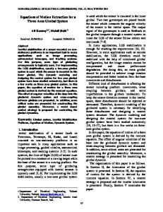
COMPUTATIONAL DETAILS Three different cases, each of which corresponds to a different rotation vector, are tested. Cases SP, ST and WN correspond to the rotation around the spanwise, streamwise and wall-normal axes, respectively. A sketch of the computational domain is shown in Fig. 1. The rotation number Roτ = 2Ωδ uτ has been increased up to 15 in Cases SP & ST. In Case WN, the maximum rotation number studied is 0.04. Five intermediate rotation cases of Roτ = 2.5, 5, 7.5, 11 and 15 were studied in Cases SP & ST, while only three intermediate rotation numbers of 0.01, 0.02 and 0.04 were preformed in Case WN. These ranges cover real conditions deduced from a conceptual design of small gas turbines of 30100 kW [6]. A fully developed flow is established with
2δ
Case SP
Figure 1 computational domain of rotating channel MEAN VELOCITIES In Case SP, asymmetric profiles of the mean velocity in the x-direction with linear slope of twice the rotation speed in the central region of the channel are recaptured well in the coarse-grid simulations. Figure 2(a) shows comparison of the present and the previous results. However, the linear profile is slightly distorted at the highest rotation number ( Roτ = 15) giving a slope lower than twice the rotation speed and shorter width of the linear profile, which indicates a tendency to laminarizing the flow. The boundary layer thickens near the suction side (denoted by S. S. at y δ = 1) and the velocity near the pressure side (denoted by P. S.) is largely decreased. In Cases SP & ST, no significant change but a little flattening of U profiles appears in both cases. Noticeable shoulders are observed in Case ST as shown in Fig. 2(b). In these two cases, the mean velocity in z-direction is induced due to the non-zero Coriolis force in that direction. The induced profiles are greatly different in each case. Four zones of opposite motions have been observed in Case ST with antisymmetric profiles around the channel centerline. The coarsegrid simulation shown in Fig 3(a) depicts this trend. The corresponding profiles in Case WN are shown in Fig. 3(b), but
2
Copyright © 2001 by ASME
the profiles are similar to that of the fully developed twodimensional channel flow. The magnitude of this velocity component increases with increasing Roτ and the flow direction is then tilted in z-direction. Due to the induced velocity in the z-direction in Cases ST & WN, the flow has three-dimensional characteristics, which is more pronounced in Case ST due to the skewed profiles. The mean flow angle γ m = tan −1 W U and the mean gradient angle γ g = tan −1 (dW dy dU dy ) differ in Case ST and change their signs more drastically, while they have closer values in Case WN (El-Samni [7]). This implies that the flow in Case WN is closer to a 2-D turbulent channel flow. A measure of flow three-dimensionality is the structure parameter a1 defined by the ratio of the vector magnitude of the shear stress to twice the turbulent kinetic energy, which is approximately constant at 0.15 in a 2DTBL. Figure 5 shows typical profiles of a1 in Cases ST & WN at the highest Roτ , where a significant distortion of a1 in Case ST can be recognized. In Case WN, a1 is much similar to a plane channel flow. This fact implies the two-dimensionality of the channel flow rotating around the wall-normal axis if one considers the mean flow direction as if it is tilted to the z-direction with an angle of γ m . The friction coefficients normalized by the value of nonrotating channel are presented in Fig. 5 using the results of coarse-grid computations along with the values deduced from fine-grid simulation, which is denoted by dotted symbols at only the highest Roτ in each case. Among the three studied cases, Case SP has distinguished behaviors at each wall.
While continuous suppression of the friction coefficient takes place on the S. S. wall, the value on the P. S. wall shows nonmonotonic behavior giving a peak near Roτ ≈7.5, beyond which continuous decrease appears indicating that increasing the rotation may lead to suppression of turbulence within the whole channel in this particular case. On the other hand the normalized C f in Cases ST & WN increases with increasing rotation in accordance with the velocity gradient observed in Fig. 2. It is noted from Fig. 5 that Case WN exhibits comparable value of C f to that of Case ST although the rotation number is much lower. If the integral of the Coriolis term in the x-momentum equation is considered in the definition of τ w , a larger value of normalized C f is obtained in Case WN as shown in Fig. 5. TURBULENT INTENSITIES The normal stresses normalized by uτ* in each rotation case are plotted along with those of non-rotating channel flow in Fig. 6. The ‘*’ has been omitted for clarity. The profiles of normal stresses at a low Roτ of 2.5 [7] have been appended to trace the changes with the rotation number in Case SP. Much suppression at the suction side can be observed in all normal components. On the pressure side uu at low Roτ reveals much suppression if compared with the augmentation in the other two components vv and ww . It should be noted that vv exceeds uu in the central region of the channel in Case SP.
2
25
Case ST
(a)
Case SP
(a) 20
1
15
* W 0
*
U
10 Plane channel Roτ = 2.5, Nishimura & Kasagi [7] Roτ = 7.6, Kristoffersen & Andersson [3] Roτ = 15
5
-1
-2
0
15
20
(b)
Case ST & WN
(b) 15
*
U
Roτ
Case WN
0.01 0.02 0.04
10
W
10
-0.5
0.0
*
5
Plane channel Case ST (Roτ = 15) Case WN (Roτ = 0.04)
5
0 -1.0
2.5 5.0 7.5 15
Roτ
0.5
0 -1.0
1.0
-0.5
0.0
0.5
1.0
y/δ
y/δ
Figure 3 Mean velocity in z-direction; (a) Case ST; and (b) Case WN.
Figure 2 Mean velocity in x-direction; (a) Case SP; and (b) Case ST & WN.
3
Copyright © 2001 by ASME
negligible due to the weak rotation numbers imposed in this case, uw and vw profiles look like uu and uv of regular channel flow. The same similarity was observed in the budgets terms of both stresses. This suggests that Case WN can be regarded as a 2D channel flow with some tilting angle in the zdirection.
In Case ST uu shows slight decrement than that of nonrotating channel near the walls associated with significant augmentation of vv and ww as shown in Fig. 6. Since no rotational production term for uu , this behavior can be attributed to the role the pressure-strain correlation plays in redistributing energy from u to v and w components. In Case WN, all the normal stresses reveal augmentation especially vv and ww , although the former has no rotational production term. In Fig. 6(c), ww shows a abrupt peak, which is shifted towards the wall and similar to that of uu . The Reynolds shear stress uv in all the studied orientations is plotted in Fig. 7, where the value of Roτ of 2.5 [7] is also appended. The non-monotonic behavior of normal stresses at either wall in Case ST is also observed in the trend of shear stress uv . Nearly zero values near the suction side can be observed at the Roτ = 15. It should be noted that the profiles of uv reveal enhancement and shifting of the linear profile down at low-to-moderate Roτ before they tend to decrease again beyond Roτ ∼ 5. This behavior was well addressed in [3] and can be attributed to the sign inversion of rotational production term in the transport equation of uv , which is a function of uu - vv . It can be seen from Fig. 6 that the rotational production term at low and higher rotation numbers is negative at wide depth of the channel, which tend to reduce uv . The sign remains positive in the vicinity of the P. S. , which in turn shifts the peak of uv towards the wall. In Cases ST & WN, uv is larger than the non-rotating case, which is attributed to the direct effect of the induced rotational production terms [7]. The off-diagonal components uw and vw are non-zeros in Cases ST & WN as shown in Fig. 8. Two additional equations for the two stresses are required when dealing with second moment closures. It is worth mentioning that budgets of the transport equations for uw and vw are studied by El-Samni [7], who finds that the rotational production terms are a key role in generating such stresses in Case ST. Such budgets would be of great help to improve current turbulence models, which fail to predict the off-diagonal stresses in the study of Oberlack et al. [5]. In Case WN, although, the rotational production terms are
RMS VORTICITY The dynamics of the vorticity have been addresses in the present study under the effect of different orientations by tracing the RMSs of vorticity fluctuations and their budgets, El-Samni [7]. Presented here is the RMS of ω x shown in Fig. 9 and compared with regular channel data. Two peaks can be observed: one at the wall as a result of the opposite signed ω x underneath the quasi-streamwise vortices and the other peak in the buffer layer due to the vortices. Although, the twp peaks exist in regular channel, their values and locations change from rotating case to another. In Case SP near the pressure side, the two peak are quite larger than regular channel flow, and the one in the buffer layer is shifted further from the wall suggesting larger diameters of the vortices. The various shapes of RMSs of ω x in Fig. 9 imply the existence of near-wall quasi-streamwise vortices of different sizes in nearwall region. HIGHER-ORDER STATISTICS The skewness and flatness factors are computed for the different variables. Presented here in Fig. 10 (a), the skewness factor for the fluctuating velocity v at different orientations. For Case WN, the skewness profiles are almost the same indicating the proximity of Case WN to 2D regular channel. In Case SP, the negative skewness near the vicinity of the wall is a natural sequence of the direct effect of Coriolis force to push fluid particles towards the wall. In Case ST, the strong excursions of positive v departing from the wall towards the channel centerline and usually penetrating to the other wall are responsible for the positive skewness factor. The flatness factor on the other hand, shows higher values near the wall in all cases except Case SP.
2.0
0.20
1.5
Cf /Cfo
Case WN Case WN (based on τ* w )
Case SP (S. S.) Case SP (P. S.) Case ST
0.15
a1
1.0
2D TBL
0.10 Plane channel Case ST (Roτ= 15) Case WN (Roτ= 0.04)
0.05
0.5
0
2
4
6
8
10
12
14
0.00 0
16
20
40
60
80
100
120
140
160
+
y
Roτ1,Roτ2, 400 Roτ3
Figure 4 Structure parameter a1 in Cases ST & WN.
Figure 5 Normalized skin friction.
4
Copyright © 2001 by ASME
3
8
6
*
uu
4
Plane channel Case SP (Roτ = 2.5) Nishimura & Kasagi [8] Case SP (Roτ = 15) Case ST (Roτ = 15) Case WN (Roτ = 0.04)
(a) uw
Case ST (Roτ = 15) Case WN (Roτ = 0.04)
vw
Case ST (Roτ = 15) Case WN (Roτ = 0.04)
2
uw vw
*
1
(b)
*
0
2 -1
0
-1.0
-0.5
0.0
(b)
Figure 8 Off-diagonal components uw and vw .
5
0.5 Plane channel Case SP (Roτ = 15) P. S. Case SP (Roτ = 15) S. S. Case ST (Roτ = 15) Case WN (Roτ = 0.04)
4 0.4 *
1.0
y/δ
6
vv
0.5
3 0.3
+
ω'x
2
0.2
1 0.1
0 4
0.0 0
(c)
20
40
+
60
80
100
y
3
Figure 9 RMS Vorticities normalized in wall unit. 1.0
ww
*
(a)
2 0.5
1
S(v) 0.0
0 -1.0
-0.5
0.0
0.5
-0.5
y/δ Figure 6 Normal stress in wall units; (a) uu ; (b) vv and (c) ww .
-1.0
1.5 1.0 0.5
uv
*
Plane channel Case SP (Roτ = 2.5) Nishimura & Kasagi [8] Case SP (Roτ = 15) Case ST (Roτ = 15) Case WN (Roτ = 0.04)
Plane channel Case SP (Roτ = 15) P. S. Case ST (Roτ = 15) Case WN (Roτ = 0.04)
1.0
20
(a)
(b) Plane channel Case SP (Roτ = 15) P. S. Case ST (Roτ = 15) Case WN (Roτ = 0.04)
15
F(v) 10
0.0 -0.5
5
-1.0 0 0
-1.5
Figure 7 Reynolds shear stress uv .
20
40
+
60
80
y
Figure 10 Skewness (a) and flatness (b) factors of v .
5
Copyright © 2001 by ASME
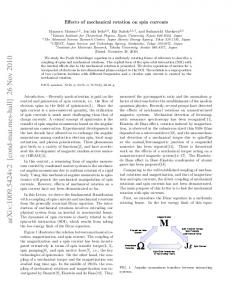
BUDGETS All terms in the transport equations of the relevant quantities to turbulence models have been calculated for the different orientations studied. All components of Reynolds stresses, vorticity fluctuations, turbulent kinetic energy, and the dissipation rate of turbulent kinetic energy are of typical quantities beside other scalar related quantities. An example of the budgets computed in the present study, is the turbulent kinetic energy normalized by the wall units, which has no explicit dependence on the rotation number. However, Fig. 11 shows four different budgets of the three orthogonal orientations and the non-rotating case as well. It can be seen the drastical changes in the different terms in the budgets compared with the non-rotating case, especially in Case SP, while the general trend in Cases ST & WN seems similar to the regular channel but with a slight scaling. TURBULENT STRUCTURES Flow visualization for the instantaneous fields is essential tool in discovering turbulent structures in wall-bounded flows when subjected to additional strains or body forces. Crossstream vectors can give clearer picture about the vortical structures and large scale eddies as it can be shown in Fig. 12. Two instantaneous fields in Cases SP & 2 are picked up shown the velocity vectors in z-y planes. It should be mentioned that Kristoffersen and Andersson [3] in Case SP at
low Roτ observed large scale eddies of Taylor-Gortler types. However, with increasing Roτ the persistence of the roll cells and their sizes decreases. In Fig. 12 (a), at Roτ = 15, such roll cells disappear. Note that the top edge of Fig. 12(a) corresponds to the pressure side. Calm region of laminar nature can be observed in the bottom edge of this figure. In Case ST different sizes of eddy motions can be observed in Fig. 12 (b) which has rotation sign similar to the back ground rotation. Note that the flow out of the page in both graphs. The fluid particles have opposite motion at both walls, resulting in the anti-symmetric profiles shown in Fig. 3(a). For capturing the vortical structure in rotating channel flows, the negative second largest eigenvalue ( λ 2 ) of the tensor S ik S kj + Ω ik Ω kj used by Jeong et al. in plane channel flow [9] which would be frame invariant and the most suitable candidate to capture vortical structures. RMS values of λ 2 are shown in Fig. 13, from which the threshold values in the visualizations are deduced. In Fig. 14, the vortical structures in three cases are embedded with the low-high speed streaks. Tilted streaks can be observed in Cases ST & WN. Less population of vortices in Case 2 is also shown; while the flow is tilted in the z-direction with more complicated structures can be shown in Fig. 14(c). 250 200
y
150
Gain
0.3
100
Pk Dk
(a)
Πk
0.2
50 0
700
(a)
0.1
600
500
400
300
200
100
0
z
300
-0.1 -0.2
200
y
Loss
0.0
Tk
εk
100
Plane channel Case SP (Roτ = 15) P. S.
-0.3
(b)
Gain
0.3
Dk
0.2
Pk
Πk
Loss
750
500
Tk
-0.1
λ'2
-0.2
Case ST (Roτ = 15) Case WN (Roτ = 0.04)
εk
y
0
Plane channel Case SP (Roτ = 15) P. S. Case ST (Roτ = 15) Case WN (Roτ = 0.04)
0.06 0.05
1
250
z
Figure 12 Cross-streamwise instantaneous velocity vector in: (a) Case SP and (b) Case ST, at Roτ = 15.
(b)
0.0
0.1
1000
0.07
0.1
-0.3
0
+
10
0.04 0.03 0.02 0.01
100
0.00 0
Figure 11 Terms in transport equation of turbulent kinetic energy: (a) non-rotating channel & Case SP and (b) Cases ST & WN.
20
40
60
80
100
120
140
+
y
Figure 13 RMS profiles of − λ2 in different rotating cases. 6
Copyright © 2001 by ASME
(a)
both cases. It is shown that system rotation, when the system vorticity is perpendicular to mean flow vorticity, affects the mechanism of generating and sustaining the vortical structures near the wall of a rotating channel. Those effects are evident in Cases ST & WN, where the tilting streaky structures and less population of the vortical structures are observed. Case WN seems to be the most sensitive among the cases studied, since it produces a comparable augmentation of turbulence at a rotation number two order of magnitude smaller than those of Cases SP & ST. Databases for turbulence quantities and transport equations are generated and will be of help to assess turbulence models incorporating rotational effects. ACKNOWLEDGMENTS This numerical work is the results of “Micro Gas Turbine/Fuel Cell Hybrid-Type Distributed Energy System” which is supported by the Department of Core Research for Evolutional Science and Technology (CREST) of the Ministry of Education, Culture, Sports, Science and Technology (MEXT).
(b)
REFERENCES [1] Johnson, J. P., Halleen, R. M. and Lezius, D. K., 1972, “Effects of Spanwise Rotation on The Structure of TwoDimensional Fully Developed Turbulent Channel Flow,” J. Fluid Mech., 56, pp. 533-557. [2] Kim, J., 1983, “The Effect of Rotation on Turbulence Structure,” In Proc. of 4th Symp. on Turbulent Shear Flows, Karlsruhe pp. 6.14-6.19. [3] Kristoffersen, R. and Andersson, H. I., 1993, “Direct Simulations Of Low Reynolds-Number Turbulent Flow in a Rotating Channel,” J. Fluid Mech., 256, pp. 163-197. [4] Andersson, H. I. and Kristoffersen, R., 1995, “Turbulence Statistics of Rotating Channel Flow,” In the Proc. of 9th Symp. on Turbulent Shear Flows, Kyoto, Japan, pp. 53-70.
(c) Figure 14 Vortical structures identified by − λ2 embedded with the streaky structures in near wall region: (a) Case SP, − λ2 = 0.056; (b) Case ST, − λ2 = 0.02; and (c) Case WN, − λ2 = 0.03. CONCLUSIONS System rotation has direct and indirect roles in modifying wall-bounded flows. Laminarization in rotating channels takes place only near the leading side in Case SP. Increasing the rotation rates may lead to laminarizing the whole flow. The linear profiles of the mean streamwise velocity are recaptured in Case SP for all the range of the rotation number, but with slight distortion at higher Roτ . Cases ST & WN exhibit more complicated flows. Three-dimensional flow characteristics can be deduced through the induced mean spanwise velocity and the generation of all Reynolds stress tensor components in
[5] Oberlack, M., Cabot, W. & Rogers, M. M., 1999, “Turbulent Channel Flow with Streamwise Rotation: Lie Group Analysis, DNS and Modelling,” In the 1st int. Symp. in Turbulence and Shear Flow Phenomena, USA, pp. 85-90. [6] Fukunaga, S., 2000, “Conceptual Design of Highly Efficient Micro-Gas Turbine,” Graduation thesis. (In Japanese) The University of Tokyo. [7] El-Samni, O., 2001, “Heat and Momentum Transfer in Turbulent Rotating Channel Flow,” Ph. D. thesis. The University of Tokyo, Tokyo, Japan. [8] Nishimura, M. and Kasagi, N., 1996, “Direct Numerical Simulation of Combined and Natural Turbulent Convection in a Rotating Plane Channel,” Proc. of 3rd KSME-JSME, Thermal Engineering Conference, Korea, Vol. 3, pp. 77-82. [9] Jeong, J., Hussain, F., Schoppa, W. & Kim, J., 1997, “ Coherent structures near the wall in a turbulent channel flow,” J. Fluid Mech. 332, pp.185-214.
7
Copyright © 2001 by ASME