testing code, monitor and repair execution. Therefore the ... The code that implements the new component representing the connector is derived, in an auto-.
The future of Software: Adaptation and Dependability⋆ Paola Inverardi and Massimo Tivoli University of L’Aquila Dip. Informatica fax: +390862433131 via Vetoio, 67100 L’Aquila {inverard, tivoli}@di.univaq.it
Abstract. Software in the near ubiquitous future (Softure) will need to cope with variability, as software systems get deployed on an increasingly large diversity of computing platforms and operates in different execution environments. Heterogeneity of the underlying communication and computing infrastructure, mobility inducing changes to the execution environments and therefore changes to the availability of resources and continuously evolving requirements require software systems to be adaptable according to the context changes. Softure should also be reliable and meet the users performance requirements and needs. Moreover, due to its pervasiveness and in order to make adaptation effective and successful, adaptation must be considered in conjunction with dependability, i.e., no matter what adaptation is performed, the system must continue to guarantee a certain degree of Quality of Service (QoS). Hence, Softure must also be dependable, which is made more complex given the highly dynamic nature of service provision. Supporting the development and execution of Softure systems raises numerous challenges that involve languages, methods and tools for the systems thorough design and validation in order to ensure dependability of the self-adaptive systems that are targeted. However these challenges, taken in isolation are not new in the software domain. In this paper we will discuss some of these challenges and possible solutions making reference to the approach undertaken in the IST PLASTIC project for a specific instance of Softure focused on software for Beyond 3G (B3G) networks.
1
Introduction
The design and the development of dependable and adaptable software applications in the near ubiquitous future (Softure) cannot rely on the classical desktopcentric assumption that the system execution environment is known a priori at ⋆
This work is a revised and extended version of [6]. It has been partially supported by the IST project PLASTIC. We acknowledge all the members of the PLASTIC Consortium and of the SEALab at University of L’Aquila for joint efforts on all the research efforts reported in this paper.
2
Paola Inverardi et al.
design time and, hence, the application environment of a Softure cannot be statically anticipated. Softure will need to cope with variability, as software systems get deployed on an increasingly large diversity of computing platforms and operates in different execution environments. Heterogeneity of the underlying communication and computing infrastructure, mobility inducing changes to the execution environments and therefore changes to the availability of resources and continuously evolving requirements require software systems to be adaptable according to the context changes. At the same time, Softure should be reliable and meet the users performance requirements and needs. Moreover, due to its pervasiveness and in order to make adaptation effective and successful, adaptation must be considered in conjunction with dependability, i.e., no matter what adaptation is performed, the system must continue to guarantee a certain degree of Quality of Service (QoS). Hence, Softure must also be dependable, which is made more complex given the highly dynamic nature of service provision. Supporting the development and execution of Softure systems raises numerous challenges that involve languages, methods and tools for the systems through design and validation in order to ensure dependability of the self-adaptive systems that are targeted. However these challenges, taken in isolation are not new in the software domain. Adaptable and re-configurable systems do exist in many software application domains from tele-communication to the software domain itself, e.g., operating systems. Dependable systems have been intensively investigated and methods and tools exist to develop them. Hence what are the new challenges for Softure? In the following we will discuss some of these challenges and possible solutions making reference to the approach undertaken in the IST PLASTIC [13] project for the specific instance of Softure as software for Beyond 3G (B3G) networks. Our thesis is that Softure requires to rethink the whole software engineering process and, in particular, it needs to reconcile the static view with the dynamic view by breaking the traditional division among development phases by moving some activities from design time to deployment and run time hence asking for new and more efficient verification and validation techniques. Dependability is achieved with a comprehensive life cycle approach from requirements to operation, to maintenance by analyzing models, testing code, monitor, and repair execution. Many software models are involved, from requirements to specification, to code. In order to support dependability of adaptable applications new modeling notations are required. These should permit to express and deal with characteristics that are crucial for a Softure, i.e., QoS, resource-awareness, evolution, reconfiguration, variability, and uncertainty. At the same time they should allow for validation techniques affordable at run time. Their cost must be sustainable under the execution environment resource constraints, e.g. time and computational resources. In order to easily and consistently integrate the modeling layer with the analysis and implementation ones, model transformation and evolution techniques should be exploited. The paper is structured as follows. In the following section we discuss the Softure characteristics in order to identify the two key challenges: adaptability and
The future of Software: Adaptation and Dependability
3
dependability. Section 3 discusses and compares different notions of adaptability with different degrees of dependability. This discussion will bring us to consider the Softure issues in a software process perspective. In Section 4, based on the previous discussion and comparison of different adaptability and dependability degrees, we discuss the requirements that the modeling notations to the design, development, and validation of Softure should satisfy. Section 5 proposes a new software process and discusses it in the scope of the PLASTIC project [13]. In Section 6 we conclude by summarizing the thesis originating from the discussion carried on through the paper.
2
Softure challenges: setting the context
Softure is supposed to execute in an ubiquitous, heterogeneous infrastructure under mobility constraints. This means that the software must be able to carry on operations while changing different execution environments or contexts. Execution contexts offer a variability of resources that can affect the software operation. Context awareness refers to the ability of an application to sense the context in which it is executing and therefore it is the base to consider (self-)adaptive applications, i.e., software systems that have the ability to change their behavior in response to external changes. It is worthwhile stressing that although a change of context is measured in terms of availability of resources, that is in quantitative terms, an application can only be adapted by changing its behavior, i.e., its functional/qualitative specification. In particular, (Physical) Mobility allows a user to move out of his proper context, traveling across different contexts. To our purposes the difference among contexts is determined in terms of available resources like connectivity, energy, software, etc. However other dimensions of contexts can exist relevant to the user, system and physical domains, which are the main context domains identified in the literature [15]. In the software development practice when building a system the context is determined and it is part of the (non-functional) requirements (operational, social, organizational constraints). If context changes, requirements change therefore the system needs to change. In standard software the pace at which context changes is slow and they are usually taken into account as evolutionary requirements. For SOFTURE context changes occur due to physical mobility while the system is in operation. This means that if the system needs to change this should happen dynamically. This notion leads to consider different ways to modify a system at run time that can happen in different forms namely (self-)adaptiveness/dynamicity and at different levels of granularity, from software architecture to line of code. Softure needs also to be dependable. Dependability is an orthogonal issue that depends on QoS attributes, like performance and all other -bilities. Dependability impacts all the software life cycle. In general dependability is an attribute for software systems that operate in specific application domains. For Softure we consider dependability in its original meaning as defined in [5], that is the trustworthiness of a computing
4
Paola Inverardi et al.
system which allows reliance to be justifiably placed on the service it delivers ... Dependability includes such attributes as reliability, availability, safety, security. Softure encompasses any kind of software system that can operate in the future ubiquitous infrastructure. The dependability requirement is therefore extended also to applications that traditionally have not this requirement. Dependability in this case represents the user requirement that states that the application must operate in the unknown world (i.e., out of a confined execution environment) with the same level of reliance it has when operating at home. At home means in the controlled execution environment where there is complete knowledge of the system behavior and the context is fixed. In the unknown world, the knowledge of the system is undermined by the absence of knowledge on contexts, thus the dependability requirement arises also for conventional applications. Traditionally dependability is achieved with a comprehensive approach all along the software life cycle from requirements to operation to maintenance by analyzing models, testing code, monitor and repair execution. Therefore the overall challenge is to provide dependable assurance for highly adaptable applications. Since dependability is achieved throughout the life cycle many software artifacts are involved, from requirements specification to code. In the rest of this paper we will consider as such artifacts only models that is idealized view of the system suitable for reasoning, developing, validating a real system. Models can be functional and non-functional and can represent different level of abstractions of the real system, from requirements to code. Our research bias is on Software Architecture, therefore we will often consider software architectural systems models. An architectural model allows the description of the static and dynamic components of the system and explains how they interact. Software architectures support early analysis, verification and validation of software systems. Software architectures are the earliest comprehensive system model along the software lifecycle built from requirements specification. They are increasingly part of standardized software development processes because they represent a system abstraction in which design choices relevant to the correctness of the final system are taken. This is particularly evident for dependability requirements like security and reliability and quantitative ones like performance.
3
Adaptabilty: 3 examples
In this section we discuss the notion of adaptability. According to what presented so far, adaptability is the ability to change a system according to context variations, e.g., driven by QoS requirements. However, the change should maintain the essence of the system that from now on we will call invariant. From Section 3.2 to Section 3.4, we will focus on evolving systems that change through adaptation. In order to classify them we propose to use a 4 dimension metric: the four Ws.
The future of Software: Adaptation and Dependability
3.1
5
The four Ws
The systems we consider can change through adaptability either their structure and/or their behavior. The four Ws characterize the nature of the change along the following four dimensions: – – – –
Why there is the need to change? What does (not) change? When does the change happen? What/Who manages the change?
Why: this dimension makes explicit the need for the change. In a Software Engineering perspective this change is always done to meet requirements. It can be because the requirements evolved or it can be that the system does not behave properly according to the stated requirements. It is also worthwhile mentioning that requirements can be functional and non functional requirements. The former class captures the qualitative behavior of a software system, its functional specification. The latter defines the systemss quantitative attributes like, performance, reliability, security, etc. What: here we discuss the part of the system that is affected by the change. Referring to architectural models, changes can affect the structure and/or the behavior. For the structure, components can get in and out, new connectors can be added and removed. For the behavior components can change their functionality and connectors can change their interaction protocols. When: this dimension captures the moment during the systems lifetime in which the change occurs. It does not mean that the change happens necessarily at run time. This dimension is related with the Static versus Dynamic issue. What/Who: this is the description of the mechanisms to achieve the change. It can be a configuration manager or it can be the system itself. Involves monitoring the system to collect relevant data, evaluating this data, make a decision about the change alternatives and then perform the actual change. In the following we will provide 3 examples of functional and non-functional adaptation. The first one has been developed in the Software Engineering research group at University of L’Aquila. 3.2
Synthesis: an approach to automatically build failure-free connectors for component-based architectures
Synthesis is a technique equipped with a tool [2, 16] that permits to assemble a component-based application in a deadlock-free way [7, 8, 18]. Starting from a set of components Off The Shelf (OTS), Synthesis assembles them together according to a so called connector-based architecture by synthesizing a connector that guarantees deadlock-free interactions among components. The code that implements the new component representing the connector is derived, in an automatic way, directly from the OTS (black-box) components interfaces. Synthesis assumes a partial knowledge of the components interaction behavior described
6
Paola Inverardi et al.
as finite state automata plus the knowledge of a specification of the system to assemble given in terms of Message Sequence Charts (MSC) [9, 19, 20]. Furthermore, by exploiting that MSC specification, it is possible to go beyond deadlock. Actually, the MSC specification is an implicit failure specification. That is we assume to specify all the desired assembled system behaviors which are failure-free from the point of view of the system assembler, rather than to explicitly specify the failure. Under these hypotheses, Synthesis automatically derives the assembling code of the connector for a set of components. The connector is derived in such a way to obtain a failure-free system. It is shown that the connector-based system is equivalent according to a suitable equivalence relation to the initial one once depurated of all the failure behaviors. The initial connector is a no-op connector that serves to model all the possible component interactions (i.e., the failure-free and the failing ones). Acting on the initial connector is enough to automatically prevent both deadlocks and other kinds of failure hence obtaining the failure-free connector.
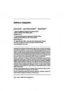
Fig. 1. The Synthesis Application Adaptation
As illustrated in Figure 1, the Synthesis framework realizes a form of system adaptation. The initial software system is changed by inserting a new component, the connector, in order to prevent interactions failures. The framework makes use of the following models and formalisms. An architectural model, the connector-based architecture that constrains the way com-
The future of Software: Adaptation and Dependability
7
ponents can interact, by forcing interaction to go through the connector. A set of behavioral models for the components that describe each single components interaction behavior with the ideal1 external context in the form of Label Transition Systems (LTSs). A behavioral equivalence on LTS to establish the equivalence among the original system and the adapted one. MSC are used to specify the behavioral integration failure to be avoided, and then LTSs and LTS synchronous product [1, 10] plus a notion of behavioral refinement [11] to synthesize the failure-free connector specification, as it is described in detail in [18]. From the connector specification the actual code can then be automatically derived as either a centralized component [18] or a distributed one [3]. The latter is implemented as a set of wrappers, one for each component, that cooperatively realize the same behavior as the centralized connector. SythesisRT. Recently, the Synthesis approach and its related tool has been extended to the context of real-time systems [17]. This extension, hereafter called SynthesisRT, has been developed by the Software Engineering research group at University of L’Aquila in cooperation with the POP ART project team at INRIA Rhˆ one-Alpes. In [17], it is shown how to deal with the compatibility, communication, and QoS issues that can raise while building a real-time system from reusable black-box components within a lightweight component model where components follow a data-flow interaction model. Each component declares input and output ports which are the points of interaction with other components and/or the execution environment. Input (resp., output) ports of a component are connected to output (resp., input) ports of a different component through synchronous links. Analogously to the version of Synthesis without real-time constraints, a component interface includes a formal description of the interaction protocol of the component with its expected environment in terms of sequences of writing and reading actions to and from ports. The interface language is expressive enough to specify QoS constraints such as writing and reading latency, duration, and controllability, as well as the component’s clock (i.e., its activation frequency). In order to deal with incompatible components (e.g., clock inconsistency, read/write latency/duration inconsistency, mismatching interaction protocols, etc.) we synthesize component adaptors interposed between two or more interacting components. An adaptor is a component that mediates the interaction between the components it supervises, in order to harmonize their communication. Each adaptor is automatically derived by taking into account the interface specification of the components it supervises. The adaptor synthesis allows the developer to automatically and incrementally build correct-by-construction systems from third-party components. Figure 2 shows the main steps of the method performed by SynthesisRT by also highlighting the used formalisms/models. We take as input the architectural specification of the network of components to be composed and the component interface specifications. The behavioral models of the components are generated in form of LTSs that make the elapsing of 1
The one expected by the component’s developer.
8
Paola Inverardi et al.
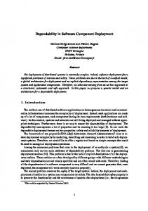
Fig. 2. Main steps of adaptor synthesis for real-time components
time explicit (step 1). Connected ports with different names are renamed such that complementary actions have the same label in the component LTSs (see actions a and d in Figure 2). Possible mismatches/deadlocks are checked by looking for possible sink states into the parallel composition of the LTSs. The adaptor synthesis process starts only if such deadlocks are detected. The synthesis first proceeds by constructing a Petri net (PN) [12] representation of the environment expected from a component in order not to block it (step 2). It consists in complementing the actions in the component LTSs that are performed on connected ports, considering the actions performed on unconnected ports as internal actions. Moreover, a buffer storing read and written values is modeled as a place in the environment PN for each IO action. Each such PN represents a partial view of the adaptor to be built. It is partial since it reflects the expectation of a single component. In particular, a write (resp. read) action gives rise to a place (buffer) without outgoing (resp. incoming) arcs. The partial views of the adaptor are composed together by building causal dependencies between the reading/writing actions and by unifying time-elapsing transitions (step 3). Furthermore, the places representing the same buffer are merged in one single place. This Unification PN models an adaptor that solves deadlocks using buffers to desynchronize received events from their emission. However, the unification PN may be not completely correct, in the sense that it can represent an adaptor that may deadlock and/or that may require unbounded buffers. In order to obtain the most permissive and correct adaptor, we generate an extended version of the graph usually known in PNs theory [12] as the coverability graph [4] (step 4).
The future of Software: Adaptation and Dependability
9
Our method automatically restricts the behavior of the adaptor modeled by the extended coverability graph in order to keep only the interactions that are deadlock-free and that use finite buffers (i.e., bounded interactions). This is done by automatically constructing, if possible, an “instrumented” version of our extended coverability graph, called the Controlled Coverability Graph (CCG). The CCG is obtained by pruning from the extended coverability graph both the sinking paths and the unbounded paths, by using a controller synthesis step [14] (step 5). This process also performs a backwards error propagation step in order to correctly take into account the case of sinking and unbounded paths originating from the firing of uncontrollable transitions. If it exists, the maximal CCG generated is the LTS modeling the behavior of the correct (i.e., deadlock-free and bounded) adaptor. This adaptor models the correct-by-construction assembly code for the components in the specified network. If it does not exist, a correct adaptor assembling the components given as input to our method cannot be automatically derived, and hence our method does not provide any assembly code for those components. Let us now analyze the Synthesis(RT) approach to adaptation by means of the four Ws metric: Why there is the need to change? Here the purpose of the change is to correct functional behavior and to make the non-functional one fit. That is to avoid interaction deadlocks (due to possible clock inconsistency, inconsistent latency/duration for the component actions, mismatching interaction protocols) and/or enforce a certain interaction property P. This adaptation is not due to changes of context simply because, at assembly time, the context does not to change. The change here aims at both correcting a functional misbehavior and making different non-functional characteristics of the components fit. What does (not) change? It changes the topological structure and the interaction behavior. A new component is inserted in the system and the overall interaction behavior is changed. The invariant part of the system is represented by all the correct behaviors. The proof that the adaptation preserves the invariant is by construction. When does the change happen? It happens at assembly time, thus prior to deployment and execution. Thus it is actually part of the development process. What/Who manages the change? An external entity: The developer through the Synthesis(RT) framework. 3.3
Topological evolution: Graph Grammars to describe software architecture styles
In this section we summarize and discuss (w.r.t. the four Ws) the work by D. Le M´etayer described in [24]. In this work the author proposes to describe software architectures formally in terms of graphs. The nodes of the graph represent the individual system entities (i.e., components, in a very general meaning).
10
Paola Inverardi et al.
The edge corresponds to the communication links (i.e., connectors) between entities. Architectural styles are defined as context-free graph grammars since they can be seen as a set of architectures (and, hence, graphs) sharing a common shape. In other words, an architectural style is the “type” (i.e., form) that an architecture conform to the style must have at run time, that is the possible interconnections between its individual entities. A “coordinator” is used to pilot the overall application, and it is in charge of managing the architecture itself (creating and removing entities and links). As an illustration, the graph shown in Figure 3 represents an example of a client-server architecture.
Fig. 3. A client-server architecture
The architecture represented by the graph shown in Figure 3 involves two clients c1 and c2, two servers s1 and s2, a manager m0 and x0. It is formally defined as the set D: {CR(c1, m0), CA(m0, c1), C(c1), CR(c2, m0), CA(m0, c2), C(c2), SR(m0, s1), SA(s1, m0), S(s1), SR(m0, s2), SA(s2, m0), S(s2), X(x0), M (m0)} where C, S, M , and X correspond, respectively, to the client, server, manager and external entity types. The external entity stands for the external world; it records requests for new clients wanting to be registered in the system. CR and CA correspond to client request links and client answer links (they are link types), respectively (SR and SA are the dual links for servers). D is just one particular representative of a more general class of client-server architectures. Architectures belonging to this class must include values X(x0) and M (m0) and any number of servers and clients. Furthermore, they must follow the communication link pattern exhibited by D. Such a class is specified as a context-free graph grammar:
The future of Software: Adaptation and Dependability
11
HCS = [{CS, CS1}, {M, X, C, S, CR, CA, SR, SA}, R, CS] where {CS, CS1} is the set of non-terminal symbols with CS the axiom (i.e., the origin of any derivation produced by applying the production rules in R), {M, X, C, S, CR, CA, SR, SA} is the set of terminal symbols, and R the set of the following four production rules: 1. 2. 3. 4.
CS → CS1(m) CS1(m) → CR(c, m), CA(m, c), C(c), CS1(m) CS1(m) → SR(m, s), SA(s, m), S(s), CS1(m) CS1(m) → M (m), X(x)
It is often the case that the architecture of an application should be able to evolve dynamically. For instance, a client-server organization must allow for the introduction of new clients or their departure. In the theoretical framework described in this section, the evolution of the architecture is defined by a coordinator. As an illustration, the following coordinator CooCS can be applied to a client-server architecture: X(x), M (m) → X(x), M (m), CR(c, m), CA(m, c), C(c) CR(c, m), CA(m, c), C(c) → ∅ The coordinator is defined as a set of production rules. The two rules above describe the introduction of a new client in the architecture and its departure, respectively. The possibility of expressing architecture transformations is definitely a useful feature but it also raises a question: is it possible to ensure that a coordinator does not break the constraints of a given architectural style? For example, had we forgotten, say CR(c, m) in the right-hand side of the first rule, then the coordinator would have been able to transform a client-server architecture into an architecture which would not belong any longer to the client-server class defined by HCS. To answer this question, in [24], the author defines a static style checking algorithm which would be the counterpart for coordinators of the type checking algorithms of classical languages. The algorithm has been applied to a real-scale case study, see [24] for further details. Let us analyze the theoretical framework based on graph grammars, that is summarized in this section, with the four Ws metric: Why there is the need to change? The change allows the topological evolution of the system (e.g., new components entering or quitting the system) according to the constraints imposed by the architectural style the system’s software architecture conforms to. What does (not) change? The topological structure of the system changes since its software architecture changes, but the imposed architectural style is preserved. Moreover, the interaction behavior does not change since the system’s components are constrained to always exhibit the same “style” of interaction.
12
Paola Inverardi et al.
When does the change happen? At run time with the introduction of a new component acting as both a coordinator of the other components in the system and a manager of the links between the system components. What/Who how is the change managed? By the coordinator and an external entity that allows the system to be open in the sense that its structure can evolve. 3.4
Topological and behavioral evolution: ArchJava
In this section we recall and discuss (w.r.t. the four Ws) the work by Aldrich et al. concerning the ArchJava2 language [25, 26]. ArchJava is an extension to Java which allows programmer to specify the architecture of the software within the program. Software architecture is the organization of a software system as a collection of components, connections between the components, and constraints on how the components interact. Architecture description languages (ADLs) can be used to specify and analyze the software architecture and, by equipping/integrating an ADL with a verification tool, Architecture specifications can be also automatically analyzed. Architecture specification is helpful in software development and maintenance since it represents the reference skeleton used to compose the system components and let them interact. The motivation for ArchJava is the following: using an ADL for specifying the architecture causes problems since there could be inconsistencies between the implementation and the specification. This becomes a bigger problem as the software changes. ArchJava extends Java with constructs for specifying the architecture of the software. Using ArchJava software developers specify the architecture of the software within the program. Therefore, the architecture and the program are always consistent in the sense that a certain set of architectural constraints always hold in the implementation of the architecture. Communication integrity is one of the architectural constraints that is worth checking when implementing an architectural specification into a program. Communication integrity means that the components only communicate directly with the components they are connected to in the architecture. By using ArchJava to implement an architectural specification into a program, the communication integrity, defined at the architectural-level, is guaranteed by the implemented program. The new language constructs introduced by ArchJava are Components, Ports, and Connections. Components are the same as usual Java classes plus architectural constraints. They define architectural objects and must obey the declared architectural constraints. Ports are points of interaction of the components with the external environment, that is they define the communication interfaces of the components by declaring the set of methods that are required and provided to enable communication. Components communicate through ports and they can send and receive ordinary (i.e., non-component) objects between each other 2
http://www.cs.washington.edu/homes/jonal/archjava/.
The future of Software: Adaptation and Dependability
13
through the ports. As an illustration, the following is a part of the ArchJava code defining a component, Parser, with an input port declaring a required method, nextToken, and an output port declaring a provided method, parse. In order to implement parse the “private” method parseExpr is used. public component class Parser { public port in { requires Token nextToken(); } public port out { provides AST parse(); } AST parse() { Token tok=in.nextToken(); return parseExpr(tok); } AST parseExpr(Token tok) { ... } ... } Components can have sub-components, i.e., several components can be composed to form a composite component. Sub-components communicate through the connected ports. Connections are used to connect different ports and components can only communicate with their sub-components (through ports) and the components that they are connected to. As an illustration, the following is a part of the ArchJava code implementing the composite component Compiler: public component class Compiler { private final Scanner scanner = new Scanner(); private final Parser parser = new Parser(); private final CodeGen codegen = new CodeGen(); connect scanner.out, parser.in; connect parser.out, codegen.in; ... Compiler is formed by three components, Scanner, Parser, and Codegen. The output port of Scanner (resp., Parser) is connected to input port of Parser (resp., Codegen). The connect primitive will bind each required method to a provided method with the same signature. The arguments to connect may be a components own ports or those of subcomponents in final fields. Connection consistency checks are performed to ensure that each required method is bound to unique provided method. For the sake of clarity, in Figure 4, we show the software architecture of Compiler. As mentioned above, ArchJava enforces communication integrity since no method calls are permitted from one component to another except either from
14
Paola Inverardi et al.
Fig. 4. Software architecture of a composite component
a parent to its immediate sub-component or through connections in the architecture. This means that, on the one hand, ArchJava allows calls either between connected components, or from a parent to its immediate sub-component, or to shared objects. On the other hand, ArchJava forbids calls either that are external to sub-components, or between unconnected sub-components, or through shared objects. In ArchJava, communication integrity can be statically checked (i.e., at compile time). This is due to way the ArchJava Type System has been designed. It enforces the following invariant: components can only get a typed reference to sub-components and connected components. Therefore, it is not possible to cast a component to an Object and avoid the restrictions on communication between components. This will cause an exception. By using ArchJava, it is also possible to establish dynamic architectures. Instances of components can be dynamically created using new syntax as with ordinary objects. At creation time each component records the component instance that created it as its parent component. Communication integrity puts restrictions on how component instances can be used. Typed references to subcomponents should not escape the scope of their parent component. This requirement is enforced by putting restrictions on how component types can be used. Connections can be formed dynamically using a connect expression. A connect expression must match a connect pattern declared at the enclosing component. A connection pattern is used to describe a set of connections that can be instantiated at run time. A connect expression matches a connection pattern if the connected ports are identical and each connected component instance is an instance of the type specified in the pattern. Let us analyze the features of the ArchJava language, that are recalled in this section, with the four Ws metric: Why there is the need to change? The change allows both the topological and behavioral evolution of the system. What does (not) change? The topological structure and the behavior of the system, e.g., new type of components can enter the system or old ones quitting it, and also new types of connections can be instantiated among components hence, possibly, introducing new interaction behavior. Whatever change is applied, communication integrity is kept, i.e., it is the invariant. When does the change happen? At run time with the dynamic creation of component and connection instances.
The future of Software: Adaptation and Dependability
15
What/Who how is the change managed? It is self-managed since the application itself steers it. Summarizing in this section we have presented 5 examples of adaptation that differ with respect to several dimensions. One issue that is raised by the when dimension in the four Ws metric is whether adaptability is static or dynamic. The system adapts at run time, how and when the adaptation is computed or carried out does not change the problem, it is just a matter of cost. The cost we are referring to here is the cost of carrying out the adaptation maintaining the original integrity of the part of the application that does not change, i.e. the invariant. Thus if the application A that exhibits property P is changed into an application A′ and the change is supposed to preserve the property P , then this means that also A′ must satisfy P . For example the property P could be type integrity, thus we require that the change does not undermines type integrity in the changed application. Obviously, in this case, carrying out the change statically, i.e. before the system is running permits to prove type integrity of A′ in a less expensive way than if done at run time.
4
Requirements on the modelling notations to support adaptation and dependability
In this section we discuss the requirements that the modelling notations for Softure should satisfy in order to specify, and reason about, computational entities that will be adaptable to the environment they will be deployed and executed. We recall that adaptability is, here, intended as the ability to change a system according to requirement changes and context variations possibly driven by QoS requirements. However, the change should maintain the behavioural essence of the system that we call invariant. This premise allows us to set a number of requirements on the notations that should be used in the context of Softure. The first consideration is that a sole unifying notation will not suffice. This implies that a bunch of modelling notations should be used and consistently integrated. These notations will characterize the software at different levels of granularity, according to the adaptation variability. They will express different attributes of interest for validation purposes. It shall be possible to characterize the invariant behaviour of the software as well as its variability and it shall be possible to define accordingly a notion of cost for the validation of the invariant part upon adaptation. The adaptation logic itself needs to be described, either embedded in the software or external but dependent on the observation of the software to adapt. Besides notations for the adaptable software, notations for characterizing the context, both statically and at run time, must be defined. Each one of the above represents a research challenge itself and opens new research opportunities. All these new notations will be used to provide a common base for behavioural and dependability analysis, model checking, model transformation, correct-by-construction code synthesis and testing. A further challenge then is to let all the different notations coexist in a common evolutionary development
16
Paola Inverardi et al.
framework based on model-transformations, which allows the definition of relationships between the different Softure notations. Summarizing, these notations should allow the developer to express context-aware adaptation in conjunction with the desired degree of dependability. In this direction, new modelling notations should be defined to support the effective development of Softure. These notations should be able to: – Express the attributes of interest, operational profile (e.g., workload, probability of usage), user preferences, testability concepts (e.g., verdict, test case, test purpose), etc. – Model relevant context characteristics to be monitored at run time to enable applications to adapt accordingly. Such notations should facilitate the management of context information (and their variations) being retrieved by different sources in a homogeneous way. They should also allow for advanced operations on contextual data, e.g., by comparing and reasoning on data for checking consistency and by combining different types of data. – Define: (i) which behavioural properties have to be considered as invariants (i.e., no matter what adaptation will be performed, these properties must be always guaranteed), and (ii) which ones can be considered parametric in the possible deployment environments. Depending on the system, on the properties and on the possible adaptations a static verification can be carried on. However, in general, their verification needs to be performed dynamically, under a certain notion of reasonable cost, in conjunction with the validation of the discovered deployment environment. Thus, how to model this notion of verification cost should also be another challenge to face. – Express how to embed the adaptation logic in the system that we assume to be made of components. Two types of approaches are possible: (i) endogenous, that requires enriching the modelling language to provide this ability into the component logic; and (ii) exogenous, that refers to an external entity able to monitor the state exported from each component and adapt the component behaviour to dynamic changes in the environment. The first case amounts to provide in the component modelling notation higher-order capabilities. The latter amounts to make the component state available (and, hence, modelled) to be inspected and managed. Both of them require notations to effectively specify a kind of “make before break policies” for preparing the adaptation before the application consistency breaks. For instance, when switching from a given context to a different one the application might change its “internal” status according to the new environment it is entering into. – Express variability in a declarative style in order to support property verification for evolving systems [34]. This requires capability in the notation to express degrees of generality in the component specification that can be instantiated, maintaining the correctness of the component, at run time depending on the execution context. The challenge, here, is providing the right balance between generality and verifiability.
The future of Software: Adaptation and Dependability
17
All these new notations would be used to provide a common base for behavioural and dependability analysis, model checking, model transformation, correct-by-construction code synthesis, testing, and reconfiguration. Since a unique notation incorporating all such aspects is unreasonable (as discussed also in [35]), we envision that all the different notations should be let coexist in a common evolutionary development framework based on model-transformations, which allows the definition of relationships between different Softure notations.
5
Softure: The process view
In this section we cast the above discussed challenges in a process view. The process view focuses on the set of activities that characterize the production and the operation of a software system. These activities are traditionally divided into activities related to the actual production of the software system and activities that are performed when the system can be executed and goes into operation. Specification, Design, Validation, and Evolution activities vary depending on the organization and the type of system being developed. Each Activity requires its Language, Methods and Tools and works on suitable artifacts of the system. For validation purposes each artifact can be coupled with a model. Models are an idealized view of the system suitable for reasoning, developing, validating a real system. To achieve dependability a large variety of models are used from behavioral to stochastic. These models represent the systems at very different levels of abstraction from requirements specification to code. The ever growing complexity of software has exacerbated the dichotomy development/static/compile time versus execution/dynamic/interpreter time concentrating as many analysis and validation activities as possible at development time. Softure puts new requirements on this standard process. The evolutionary nature of Softure makes unfeasible a standard approach to validation since it would require before the system is in execution to predict the system behavior with respect to virtually any possible change. Therefore in the literature most approaches that try to deal with the validation of dynamic software system concentrate the changes to the structure by using graph and graph grammars formalisms or topological constraints [24, 27–31]. As far as changes to behavior are concerned, only few approaches exist that make use either of behavioral equivalence checks or of the type system [25, 26, 32] or through code certification [23, 33]. If dependability has to be preserved through adaptation, whatever the change mechanism is, at the time the change occurs a validation check must be performed. This means that all the models necessary to carry on the validation step must be available at run time and that the actual validation time becomes now part of the execution time. The Future development process therefore has to explicitly account for complex validation steps at run time when all the necessary information are available. Figure 5 represents the process development plane delimited on one side by the standard process and on the other side by the future development one. The vertical dimension represents the static versus dynamic time with respect to
18
Paola Inverardi et al.
Fig. 5. The Future Engineering Process
the analysis and validation activities involved in the development process. The horizontal axis represents the amount of adaptability of the system, that is its ability to cope with evolution still maintaining dependability. The standard development process carries out most of the development and validation activities before the system is running that is during development. The result is a running system that, at run time, is frozen with respect to evolution. Considering development processes that allow increasingly degrees of adaptability allows to move along the horizontal axis thus ideally tending to a development process that is entirely managed at run time. In the middle we can place development processes that allow larger and larger portions of the system to change at run time and that make use for validation purposes of artifacts that can be produced statically. In the following section we introduce an instance of the Future Engineering Process that has been proposed in the scope of the PLASTIC project. 5.1
PLASTIC services: an instance of Softure
The PLASTIC project aims to offer a comprehensive provisioning platform for software services deployed over B3G networks (see Figure 6). A characteristic of this kind of infrastructure is its heterogeneity, that is it is not possible to assume that the variety of its components QoS is homogenized through a uniform layer. PLASTIC aims at offering B3G users a variety of application services exploiting the network’s diversity and richness, without requiring systematic availability of an integrated network infrastructure. Therefore the PLASTIC platform needs to enable dynamic adaptation of services to the environment with respect to resource availability and delivered QoS, via a development paradigm based on Service Level Agreements (SLA) and resource-aware programming. The provided services should meet the user demand and perception of the delivered QoS, which varies along several dimensions, including: type of service, type of user, type of access device, and type of execution network environment.
The future of Software: Adaptation and Dependability
19
Fig. 6. B3G Networks
Referring to the challenges discussed in Section 2, this means that services must be dependable according to the users expected QoS. This demands for a software engineering approach to the provisioning of services, which encompasses the full service life cycle, from development to validation, and from deployment to execution. The PLASTIC answer to the above needs is to offer a comprehensive platform for the creation and provisioning of lightweight, adaptable services for the open wireless environment. Supporting the development of resource-aware and self-adapting components composing adaptable services requires focusing on the QoS properties offered by services besides the functional ones. The whole development environment is based on the PLASTIC Conceptual Model [36] whose main role is to provide an abstract characterization of B3G networks so as to ease the development of applications that effectively exploit them. To this end, the model proposes an elicitation of base abstractions that need to be accounted for developing applications for B3G networking infrastructures. Starting from the analysis of the characteristics of B3G networks, the relevant abstractions have been identified and refined according to the PLASTIC goals. The model considers the Service-Oriented Architecture (SOA), as it offers significant benefits for the development of applications in the open B3G networking environment. It relates and refines SOA concepts with concepts associated with B3G networking abstractions. The result is a reference model for service-oriented B3G applications, which formalizes the concepts needed to realize context-aware adaptable applications for B3G networks. The model is specified using UML diagrams, and is aimed at both application and middleware developers (see Figure 7). Indeed,
20
Paola Inverardi et al.
a number of abstractions may be made available by the middleware layer, thus reusable by applications.
Fig. 7. A reference model for B3G networks
Recently, several approaches to conceptualize the world of services have been proposed. The PLASTIC model takes the move from the SeCSE conceptual model [37, 38] that it has been suitably extended to reflect all the concepts related to B3G networks and service provision in B3G networks. In particular, it focusses on the following key concepts: – Service Level Agreement that clearly set commitment assumed by consumers and providers and builds on services descriptions that are characterized functionally, via a service interface and non-functionally via a Service Level Specification (SLS ). – Context awareness and adaptation as the context is a key feature distinguishing services in the vast B3G networking environment. B3G networking leads to have diverse user populations, changing availability in system resources, and multiple physical environments of service consumption and provisioning. It is then crucial that services adapt as much as possible to the context for the sake of robustness and to make themselves usable for given contexts. As illustrated in Figure 8 adaptability is achieved by transferring some of the validation activities at run time by making available models for different kind
The future of Software: Adaptation and Dependability
21
of analysis. In particular stochastic models and behavioral ones will be made available at run time to allow the adaptation of the service to the execution context and service on line validation, respectively. In PLASTIC all the development tools will be based on the conceptual model exploiting as much as possible model-to-model transformations. The definition of a service will consists of a functional description and of a SLS that defines the QoS characteristics of the service. The overall service description is obtained by means of an iterative analysis specification phase that makes use of behavioral and stochastic models. These models suitably refined with pieces of information coming from the implementation chain, will then be made available as artifacts associated to the service specification.
Fig. 8. The PLASTIC Development Process Model
The main novelties of the PLASTIC process model is to consider SLS as part of a Service Model, as opposite to existing approaches where SLS consists, in best cases, in additional annotations reported on a (service) functional model. This peculiar characteristic of our process brings several advantages: (i) as the whole service model is driven by the conceptual model, few errors can be introduced in the functional and non-functional specification of a service; (ii) SLS embedded within a service model better supports the model-to-model transformations towards analysis models and, on the way back, better supports the feedback of the
22
Paola Inverardi et al.
analysis; (iii) in the path to code generation, the SLS will drive the adaptation strategies. With respect to the spectrum presented in Figure 5 the PLASTIC development process will present a limited form of adaptability as shown in Figures 9 and 13. The components implementing PLASTIC services will be programmed using the resource aware programming approach described in [21, 22] by using Java.
Fig. 9. The PLASTIC Artifacts to be registered at deployment time
In PLASTIC adaptation happens at the time the service request is matched with a service provision. To better understand how the matching process might operate, it is useful to refer to the reference style for SOA. Moreover it also useful to recall the roles played by the main logic entities (Service registry, Service Provider and Service Consumer) involved in the Service Oriented Interaction Pattern for service publications, discovery and binding (see Figure 10). The steps involved in the service provision and consumption are: 1. service providers publish their service descriptions into a service registry (the directory of services) so that the service consumer can locate them. 2. According to the service request format, service consumers query the service registry to discover service providers for a particular service description. 3. If one or more providers are present in the service registry at the moment of the request the service consumer can select and bind to any of them. The service registry communicate (according to the service response format) to the service consumer how to communicate with that provider. 4. When a service requester binds to the service provider, the latter returns a reference to a service object that implements the service functionality. Since the PLASTIC service provision will take advantage of Web Services (WS) technology, it is useful to instantiate the above described interaction pat-
The future of Software: Adaptation and Dependability
23
Fig. 10. Service Oriented Interaction Pattern
tern in the context of WS. Within the Web Services Interaction Pattern the Web Services Description Language (WSDL) forms the basis for the interaction. Figure 11 illustrates the use of WSDL.
Fig. 11. Web Services Interaction Pattern
The steps involved (in the case of request-response operation call) are: 1. the service provider describes its service using WSDL. This definition is published into the registry of services. For instance the registry could use Universal Description, Discovery, and Integration (UDDI). Other forms of registry and other discovery meccanisms can also be used (e.g., WS-Inspection WSDiscovery).
24
Paola Inverardi et al.
2. The service consumer issues one or more queries to the directory to locate a service and determine how to communicate with that service. 3. Part of the WSDL provided by the service provider is passed to the service consumer. This tells the service consumer what the requests and responses are for the service provider. 4. The service consumer uses the WSDL to send a request to the service provider. 5. The service provider provides the expected response to the service consumer. In Figure 11 all the messages are sent using the envelope provided by SOAP and, usually, HTTP is used as communication protocol. In general other means of connection may be used since WSDL does not force a specific communication protocol. Considering PLASTIC adaptation, the WS interaction pattern is slightly modified in order to reach the SLA at the end of the discovery phase. The steps involved in the PLASTIC service provision and consumption might be the ones as shown in Figure 12.
Fig. 12. PLASTIC Services Interaction Pattern
In particular, the discovery process has to take into account the user’s QoS request (i.e., the requested SLS) and the service SLSs (i.e., the offered SLSs). The result of the match (between the user’s QoS and the service SLSs) will produce the SLA that defines the QoS constraints of the service provision. During this matching process, in order to reach an SLA the service code might need to be adapted according to the previously mentioned resource aware programming approach hence resulting in a customized service code that satisfies the user’s QoS request and results in a SLA. Figure 13 shows an instance of the process model shown in Figure 8. It is a particular example of the PLASTIC development process.
The future of Software: Adaptation and Dependability
25
Fig. 13. The PLASTIC Development Process: an example
With respect to the service model analysis, in Figure 13 we have focused on performance and reliability. SAP•one/XPRIT starts from annotated UML diagrams and generates a performance model that may be a Queueing Network (QN) that represents a Software Architecture, if no info about the executing platform is available; or it may be an Execution Graph (representing the software workload) and a QN (representing the executing platform) if (some alternative for) the executing platform is available. The model solution provides performance indices that are parametric in the first case and numerical in the second one. A QN solver like SHARPE provides values of these performance indices. COBRA is a tool that, starting from annotated UML diagrams, generates a reliability model for component-based or service-based systems. The model takes into account the error propagation factor. The COBRA solver performs reliability analysis on the basis of the generated model. Model-to-Model transformations are performed by means of the ATLAS Transformation Language (ATL) [39] that has been developed in the context of the MODELWARE European project [40]. With respect to service validation/testing, two kinds of validation are performed: off-line and on-line validation. The former is performed before the service execution and it serves to generate test cases. The latter is performed whilst the service is running and exploits the previously generated test cases. The validation framework of the PLASTIC project is described in Chapter BBB of this tutorial volume. Thus we refer this chapter for further details.
26
5.2
Paola Inverardi et al.
The PLASTIC development environment
In this section we provide an overall description of the PLASTIC development environment that implements a part of the PLASTIC development process shown in Figure 13 (i.e., those process activities regarding the service model specification, model functional and non-functional analysis, resource-aware analysis and development, and code synthesis). The PLASTIC development environment is one of the three main blocks forming the integrated PLASTIC platform (see Figure 14).
Fig. 14. The integrated PLASTIC platform
As it is shown in Figure 14, in order to enable the development of robust distributed lightweight services in the B3G networking environment, the PLASTIC platform can be organized into three main blocks: (i) a development environment, (ii) a middleware, and (iii) a validation framework. In the following, we discuss the main aspects of the PLASTIC development environment that concern our main contribution to the PLASTIC project. The middleware and the validation framework will not be further discussed. We refer to [36] and to Chapter BBB, of this tutorial volume, for a detailed description of the middleware and the validation framework, respectively.
The future of Software: Adaptation and Dependability
27
As it has been already mentioned above, all the architectural elements of the PLASTIC platform rely on a concrete implementation of concepts defined in the PLASTIC conceptual model. The PLASTIC conceptual model has to be considered more than documentation and a basis for common understanding. In fact, it defines all the guide principles and the main conceptual elements that should be considered in order to rigorously design an integrated framework for the modeling, analysis, development, validation, and deployment of robust lightweight services over B3G networked environments. The PLASTIC development environment can be organized into five main blocks (see Figure 15): (i) modeling tools, (ii) non-functional analysis tools, (iii) code generation tools, (iv) resource- aware programming model, and (v) resourceaware adaptation tools. The PLASTIC development environment allows the developer to perform all the service design, analysis and development activities defined by the PLASTIC development process and to manage the process artifacts produced by these activities. The overall design depicted in Figure 15 should be interpreted as a layered architecture: an architectural block that is situated at an upper layer depends on some artifacts produced by using an architectural block that is situated at a lower layer. For instance, the service model built by using the modeling tools is exploited by both the non-functional analysis and code generation tools or, just to give another example, “Universal Queueing Network solver” exploits the output of “UML to Queueing Network transformation tool”. The PLASTIC development environment relies on the Eclipse framework [41], i.e., all the tools of the PLASTIC development environment are implemented as Eclipse plug-ins. In this way, the development environment results in a fullyintegrated environment relying on the Eclipse IDE. Although a single tool of the development environment is implemented as an Eclipse plug-in, it has been developed in a modular way hence providing also an API that would allow a developer to use the tool also outside Eclipse. This has been done to promote the use of PLASTIC solutions also outside the development scenario considered within the PLASTIC project. The modeling tools block is constituted of two modeling tools: the service model editor, and the SLA editor. The former is an UML2 modeling editor customized in order to be PLASTIC oriented. That is, it embeds a customized UML2 profile which is suited to model dependable and adaptable services over B3G networked environments. It is called “PLASTIC UML2 profile” and it is a concrete implementation of the PLASTIC conceptual model. The service model editor allows the developer to specify the functional interface of the service plus its behavioral and non-functional characteristics (e.g., the orchestration of those (sub-)services that form the service under design, or the QoS characteristics of a service operation respectively). Furthermore, it allows the specification of context-aware behavior with respect to two kinds of context: the device context and the network context. The device context is given in terms of the set of resources (and their characteristics) available on a possible execution environment (e.g., a device modeled as a set of a “display” resource with specific “resolution” and “refresh frequency” values, and a “CPU” resource with a specific “clock fre-
28
Paola Inverardi et al.
Fig. 15. The PLASTIC development environment
quency” value). The network context is given in terms of “mobility patterns” [42], i.e., the set of the different network types the device over which the service runs can possibly move on. Once the context-aware behavior of the service is specified, by using the service model editor, the developer can also specify how the service has to adapt to the possible context changes by still maintaining a certain degree of dependability. The SLA editor is a GUI for “SLAng” which is a language for writing SLAs. It allows the developer to specify which are the parties involved in the agreement (e.g., “doctor” and “eHealth provider”), the contractual constraints defining the agreement (e.g., “service availability greater than 80%”), and the penalties that must be applied in the case of agreement violation (e.g., “the eHealth provider will provide one month of the service for free”). The syntax and semantics of SLAng are defined by means of EMOF (a language similar to UML class diagrams) and OCL, respectively. In particular, EMOF models specify the meta-model of SLAng, that is its abstract syntax in terms of the modeling constructs and their relationships (such as throughput constraints, availability, environment, schedules, etc.) that will be used for specifying SLAs. The models conforming to the SLAng meta-model are checked with respect to OCL constraints which specify the semantics of the language in a declarative way. The service model editor and the SLA editor are integrated through a model-to-code transformation. In particular, once the service model has been specified, a model-to-code transformation can be performed in
The future of Software: Adaptation and Dependability
29
order to translate the parts of the service model that are needed for specifying the agreement (e.g., parties, possible services, operations, etc.) into a HUTN (Human-Usable Textual Notation) file which is one of the file format that can be imported by the SLA editor. The “PLASTIC Model to HUTN” tool, depicted in the block “Code Generation Tools”, performs this transformation which has been implemented using the JET transformation technology [41]. The non-functional analysis tools block is constituted of two performance analysis tools: “UML to Queueing Networks transformation tool” and “Universal Queueing Network solver”. The former is a model-to-model transformation tool that automatically translates the parts of the service model that are needed for performance analysis (they are annotated UML2 diagrams which conform to the PLASTIC UML2 profile) into a performance model that is a Queueing Network (QN) model. This tool has been implemented by using the UML2 APIs available in Eclipse [43]. Then, the QN model solution is performed by using “Universal Queueing Network solver” that is deployed as an independent tool, i.e., a web service so that it can be used also outside the PLASTIC development scenario. The resource-aware programming model and the resource-aware adaptation tools blocks are the main constituents of the framework described in [21, 22]. Since a discussion on these two blocks is not crucial for the purposes of this paper, for the sake of brevity, we refer to [21, 22] for them. The code generation tools block is constituted of five model-to-code transformation tools. The functionality provided by the “PLASTIC Model to HUTN” transformation tool has been briefly described above in the discussion concerning the integration between the service model editor and the SLA editor. The “PLASTIC Model to WSDL” transformation tool starts from the PLASTIC service functional interface, modeled by using the service model editor, and automatically generates the WSDL of the provider-side code of the service. Once this WSDL is obtained, in order to automatically derive the skeleton of the provider-side code of the service, it is enough to use the facilities provided by a suitable application server or SOAP engine (e.g., Axis in the case of Web Services). The “SLA monitor generator” transformation tool starts from the HUTN file completed by using the SLA editor and automatically generates the code of Axis handlers used to the run-time monitoring of SLAs. Analogously, “WS-Agreement generator” takes into account the HUTN file and automatically generates WS-Agreements. SLAng is maintained for SLA specification purposes while WS-Agreement is used for validation purposes. The “WS-Agreement generator” enables the integration between the modeling layer of the PLASTIC platform and the validation one. The “PLASTIC Model to Adaptable JAVA” tool starts from a specific part of the service model called “implementation view”. The implementation view models how the service is implemented in terms of software components (and their relationships) which, in turn, are implemented in terms of “adaptable” classes. By taking into account such an implementation view, the “PLASTIC Model to Adaptable JAVA” transformation tool automatically translates the implementation view into the corresponding adaptable JAVA code. This is only a skeleton code and its logic has to be coded by hand.
30
6
Paola Inverardi et al.
Conclusions
In this paper we have discussed our point of view on software in the future. Adaptability and Dependability will play a key role in influencing models, languages and methodologies to develop and execute future software applications. In a broader software engineering perspective it is therefore mandatory to reconcile the static/compile time development approach to the dynamic/interpreter oriented one thus making models and validation technique manageable lightweight tools for run time use. There are several challenges in this domain. Programming Language must account in a rigorous way of quantitative concerns, allowing programmers to deal with these concerns declaratively. Models must become simpler and lighter by exploiting compositionality and partial evaluation techniques. Innovative development processes should be defined to properly reflect these new concerns arising from software for ubiquitous computing. We presented the Plastic approach to service development and provision in B3G networks as a concrete instance of the problem raised by Softure. The solutions we are experimenting in Plastic are not entirely innovative per se rather they are used in a completely new and non trivial fashion. Summarizing our message is that in the Softure domain it is important to think and research point to point theories and techniques but it is mandatory to re-think the whole development process in order to cope with the complexity of Softure and its requirements.
References 1. A. Arnold. Finite Transition Systems. In International Series in Computer Science. Prentice Hall International (UK), 1989. 2. M. Autili, P. Inverardi, A. Navarra, and M. Tivoli. Synthesis: A tool for automatically assembling correct and distributed component-based systems. In 29th International Conference on Software Engineering (ICSE 2007), Minneapolis, MN, USA, pages 784–787, 2007. IEEE Computer Society. DOI REF: http://doi.ieeecomputersociety.org/10.1109/ICSE.2007.84. 3. M. Autili, L. Mostarda, A. Navarra, and M. Tivoli. Synthesis of decentralized and concurrent adaptors for correctly assembling distributed componentbased systems. Journal of Systems and Software, 2008. To appear. DOI REF: http://dx.doi.org/10.1016/j.jss.2008.04.006. 4. A. Finkel. The minimal coverability graph for Petri nets. In Proc. of the 12th APN, volume 674 of LNCS, 1993. 5. IFIP WG 10.4 on Dependable Computing and Fault Tolerance: http://www.dependability.org/wg10.4/. 6. P. Inverardi. Software of the future is the future of Software? In Trustworthy Global Computing, volume 4661 of LNCS. Springer Berlin/Heidelberg, 2007. 7. P. Inverardi and M. Tivoli. Deadlock-free software architectures for com/dcom applications. Elsevier Journal of Systems and Software - Special Issue on componentbased software engineering, 65(3):173–183, 2003. 8. P. Inverardi and M. Tivoli. Software Architecture for Correct Components Assembly. In Formal Methods for the Design of Computer, Communication and Software Systems: Software Architecture, volume 2804 of LNCS. Springer-Verlang Berlin/Heidelberg, 2003.
The future of Software: Adaptation and Dependability
31
9. ITU Telecommunication Standardisation sector, ITU-T reccomendation Z.120. Message Sequence Charts. (MSC96). Geneva. 10. R. Keller. Formal verification of parallel programs. Communications of the ACM, 19(7):371–384, 1976. 11. R. Milner. Communication and Concurrency. Prentice Hall, New York, 1989. 12. T. Murata. Petri nets: Properties, analysis and applications. Proceedings of the IEEE, 77(4), 1989. 13. PLASTIC IST Project. Home page on line at: http://www.ist-plastic.org. 14. P. Ramadge and W. Wonham. The control of discrete event systems. Proceedings of the IEEE, 1(77), 1989. 15. B. Schilit, N. Adams, and R. Want. Context-aware computing applications. In IEEE Workshop on Mobile Computing Systems and Applications, Santa Cruz, CA, US, 1994. 16. M. Tivoli and M. Autili. SYNTHESIS, a Tool for Synthesizing Correct and Protocol-Enhanced Adaptors. RSTI L’Objet journal, 12(1):77–103, 2006. 17. M. Tivoli, P. Fradet, A. Girault, and G. Goessler. Adaptor synthesis for real-time components. In International Conference on Tools and Algorithms for the Construction and Analysis of Systems (TACAS 2007), member of ETAPS’07, volume 4424 of LNCS, pages 185–200. Springer-Verlang Berlin/Heidelberg, 2007. 18. M. Tivoli and P. Inverardi. Failure-free coordinators synthesis for component-based architectures. Science of Computer Programming, 71(3), pp. 181-212, May 2008. DOI REF: http://dx.doi.org/10.1016/j.scico.2008.03.001. 19. S. Uchitel and J. Kramer. A workbench for synthesising behaviour models from scenarios. In Proceeding of the 23rd IEEE International Conference on Software Engineering (ICSE01), 2001. 20. S. Uchitel, J. Kramer, and J. Magee. Detecting implied scenarios in message sequence chart specifications. In ACM Proceedings of the joint 8th ESEC and 9th FSE. ACM press, 2001. 21. P. Inverardi, F. Mancinelli, M. Nesi A Declarative Framework for adaptable applications in heterogeneous environments. Proceedings of the 19th ACM Symposium on Applied Computing, 2004. 22. F. Mancinelli,P. Inverardi. Quantitative resource-oriented analysis of Java (adaptable) applications In ACM Proceedings Workshop on Software Performance, 2007. 23. G. C. Necula. Proof-Carrying Code. In N. D. Jones, editor, Proceedings of the Symposium on Principles of Programming Languages, pages 106–119, Paris, France, Jan. 1997. ACM Press. 24. D. Le M´etayer. Describing Software Architecture Styles Using Graph Grammars. IEEE Transaction on software engineering, 24(7), 1998. 25. J. Aldrich, C. Chambers, and D. Notkin. ArchJava: Connecting Software Architecture to Implementation. In Proceedings of ICSE’02, May 2002. 26. J. Aldrich, C. Chambers, and D. Notkin. Architectural Reasoning in ArchJava. In Proceedings of ECOOP’02, June 2002. 27. D. Hirsch, P. Inverardi, and U. Montanari. Graph grammars and constraint solving for software architecture styles. In Proc. of the 3rd Int. Software Architecture Workshop (ISAW-3), pages 6972. ACM Press, 1998. 28. I. Georgiadis, J. Magee, and J. Kramer. Self-organising software architectures for distributed systems. In Proc. of the 1st Work. on Self-Healing Systems (WOSS02), pages 3338. ACM Press, 2002. 29. J. Magee and J. Kramer. Dynamic structure in software architectures. In Proc. of the 4th ACM SIGSOFT Symp. On Foundations of Software Engineering (FSE-4), pages 314. ACM Press, 1996.
32
Paola Inverardi et al.
30. G. Taentzer, M. Goedicke, and T. Meyer. Dynamic change management by distributed graph transformation: Towards onfigurable distributed systems. In Proc. of the 6 In Workshop on Theory and Application of Graph Transformation (TAGT98). LNCS 1764, Springer, 1998. 31. L. Baresi, R. Heckel, S. Th¨ one, D. Varr´ o Style-Based Refinement of Dynamic Software Architectures. WICSA 2004: 155-166. 32. R. Allen and D. Garlan, A Formal Basis for Architectural Connection. ACM Transactions on Software Engineering and Methodology, 6(3):213–249, July 1997. 33. G. Barthe, Mobius, securing the next generation of java-based global computers. ERCIM News, 2005. 34. P. Inverardi and L. Mostarda: DESERT: a decentralized monitoring tool generator. IEEE Proceeding of ASE 2007, tool demo. 35. V. Cortellessa, A. Di Marco, P. Inverardi, F. Mancinelli and P. Pelliccione, A framework for integration of functional and non-functional analysis of software architectures. ENCS 116: 31-44 (2005). 36. PLASTIC IST Project. Home page on line at: http://www.ist-plastic.org. 37. SeCSE Project http://secse.eng.it. 38. M. Colombo, E. Di Nitto, M. Di Penta, D. Distante, and Maurilio Zuccal. Speaking a Common Language: A Conceptual Model for Describing Service-Oriented Systems 3rd International Conference on Service Oriented Computing (ICSOC 2005). 39. F. Jouault and I. Kurtev, Transforming Models with ATL. In J. M. Bruel, editor, MoDELS Satellite Events, volume 3844 of LNCS, pages 128 138. Springer-Verlag, 2005. 40. ModelWare, IST European project 511731. http://www.modelware- ist.org 41. F. Budinsky, D. Steinberg, E. Merks, R. Ellersick, and T. J. Grose, Eclipse Modeling Framework. Addison-Wesley. 2003. 42. A. Di Marco and C. Mascolo. Performance Analysis and Prediction of Physically Mobile Systems. WOSP 2007. 43. Eclipse project. Model Development Tools UML2. http://www.eclipse.org/modeling/mdt/?project=uml2.