IEEE TRANSACTIONS ON NUCLEAR SCIENCE, VOL. 48, NO. 3, JUNE 2001
567
The GREAT Triggerless Total Data Readout Method I. H. Lazarus, Member, IEEE, D. E. Appelbe, P. A. Butler, P. J. Coleman-Smith, Member, IEEE, J. R. Cresswell, S. J. Freeman, R. D. Herzberg, I. Hibbert, D. T. Joss, S. C. Letts, R. D. Page, V. F. E. Pucknell, P. H. Regan, J. Sampson, J. Simpson, J. Thornhill, and R. Wadsworth
Abstract—Recoil decay tagging (RDT) is a very powerful method for the spectroscopy of exotic nuclei. RDT is a delayed coincidence technique between detectors usually at the target position and at the focal plane of a spectrometer. Such measurements are often limited by dead time. This paper describes a novel triggerless data acquisition method, which is being developed for the gamma recoil electron alpha tagging (GREAT) spectrometer, that overcomes this limitation by virtually eliminating dead time. Our solution is a total data readout (TDR) method where all channels run independently and are associated in software to reconstruct events. The TDR method allows all the data from both target position and focal plane to be collected with practically no dead-time losses. Each data word is associated with a timestamp generated from a global 100-MHz clock. Events are then reconstructed in real time in the event builder using temporal and spatial associations defined by the physics of the experiment. Index Terms—Alpha-particle spectroscopy, beta-ray spectroscopy, coincidence circuits, data acquisition, gamma-ray spectroscopy, nuclear physics, triggering.
I. INTRODUCTION
T
HE gamma recoil electron alpha tagging (GREAT) spectrometer [1] will be used in nuclear structure physics experiments to analyze the decay particles and gamma rays of recoiling nuclei produced in heavy-ion fusion reactions. Initially, it will be used at the focal plane of RITU [2], the recoil separator at Jyväskylä, Finland. Normally, the spectrometer will be used in conjunction with a target position detector array to collect prompt gamma rays or conversion electrons emitted during the initial stages of the decay of the recoiling nucleus. Examples of target position detector arrays to be used with GREAT are VEGA [3] or Jurosphere [4] for gamma rays and SACRED [5] for conversion electrons. Fig. 1 shows a generic experimental setup for GREAT Manuscript received November 1, 2000; revised January 18, 2001. This work was supported by the U.K. Engineering and Physical Science Council (EPSRC) under Grant GR/M79998/01 and by the European Community—Access to Research Infrastructure action of the Improving Human Potential Programme—under Contract HPRI-1999-CT-50017. I. H. Lazarus, D. E. Appelbe, P. J. Coleman-Smith, S. C. Letts, V. F. E. Pucknell, and J. Simpson are with Daresbury Laboratory, Warrington WA4 4AD, U.K. (e-mail:
[email protected]). P. A. Butler, J. R. Cresswell, R. D. Herzberg, I. Hibbert, R. D. Page, J. Sampson, and J. Thornhill are with Oliver Lodge Laboratory, University of Liverpool, Liverpool L69 7ZE, U.K. S. J. Freeman is with Department of Physics and Astronomy, University of Manchester, Manchester M13 9PL, U.K. D. T. Joss is with the School of Sciences, Staffordshire University, Stoke on Trent ST4 2DE, U.K. P. H. Regan is with Department of Physics, University of Surrey, Guildford GU2 7XH, U.K. R. Wadsworth is with Department of Physics, University of York, York YO10 5DD, U.K. Publisher Item Identifier S 0018-9499(01)04902-4.
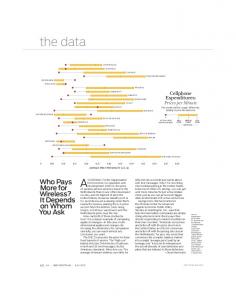
Fig. 1. Typical GREAT experiment configuration at Jyväskylä with a target array detecting either gamma rays or conversion electrons and a recoil separator.
at Jyväskylä, where an incoming heavy ion beam hits a target in the center of a detector array sensitive either to conversion electrons or to gamma rays. The resulting fusion products pass through the magnets, which act as a recoil separator to select certain mass-charge-energy combinations for transmission to the GREAT detectors at the focal plane. The GREAT spectrometer uses five focal plane detector types: 1) 28 silicon p-i-n diodes for conversion electrons;, 2) silicon (Si) strip detectors (two-dimensional, 60 40) for recoils and for alpha and beta decays; 3) multiwire proportional chamber (MWPC) for recoil detection and identification; 4) planar germanium (Ge) strip detector (two-dimensional, 24 12) to detect betas and low-energy photons; 5) segmented large volume Ge detector for higher energy gammas. Recoil decay tagging (RDT) [6] experiments collect data at three distinct stages: first prompting radiation at the target position, secondly recoiling nuclei as they emerge from the recoil separator into GREAT, and thirdly emissions from decays of implanted nuclei in the GREAT spectrometer’s detectors. Each of these three stages contributes to the triggering. The delay between the prompt radiation and detection of recoils in GREAT depends on the mass and energy of the recoiling nucleus and also the characteristics of the spectrometer. Times of flight range from 0.5 to 5 s. Emissions of gamma rays, alphas, betas, or electrons from implanted nuclei in the Si strip detectors can take place over a wide range of times from a few nanoseconds to hundreds of seconds. The correlation between the decaying implanted nuclei and the other data is made positionally and relies on having only one recoil per pixel in the Si
0018–9499/01$10.00 © 2001 IEEE
568
IEEE TRANSACTIONS ON NUCLEAR SCIENCE, VOL. 48, NO. 3, JUNE 2001
strip detectors within the correlation interval. The correlation of recoils with their subsequent decays is at the heart of the RDT technique. II. CONVENTIONAL RDT TRIGGERING Up to now, RDT experiments have normally used a common dead-time data-acquisition system where a trigger condition might typically be that any focal plane detector is active. This occurs some microseconds after the radiation is emitted at the target position because of the recoil’s time of flight through the separator. The time of flight delay is overcome by using delayed coincidence mode in the analog-to-digital converters (ADCs) instrumenting the target array. This means that the target position ADCs are gated whenever a recoil is detected at the focal plane at a rate of up to 10 kHz (assuming 10% efficiency for transmission to focal plane and 100-kHz target rate). Singles data at the target position are collected separately for monitoring purposes but not written to tape. The gate width depends on the decay lifetime of the implanted nuclei. Typically gate widths of up to 5 s are used. This period is sufficient to include recoil implantations at the focal plane and decay of short lived isomers to the ground state as well as gammas at the target. (Focal plane alpha and beta ground state decays take place much later and are recorded in separate events.) During the gate period, all ADCs that fire are converted and written to tape along with a single timestamp based on the start of the gate. Both good data and randoms (rubbish) are written to tape at a rate of up to 10 kHz (rate depends on the type of reaction under study). Dead time can be calculated assuming a rate of 5 kHz at the focal plane in the silicon detector and allowing 35 s for the gate and for readout of the ADCs. In this case, we have a dead time of 18%, rising to 35% if the rate in the Silicon detector increases to 10 kHz. Obviously, longer gates increase the dead time still further. Longer gates are desirable for studying isomeric decays where, for example, an isomer with a half-life of 10 s requires a gate of 40–50 s. However, a 50- s gate, with readout time added, and a rate of 10 kHz leads to a dead time of 75%, and a 50- s gate incorporates a lot of random gammas from the target position’s delayed coincidence ADCs. Another problem related to dead time is that during readout, the focal plane electronics is dead, which means that any further alpha or beta ground state emissions are missed. These are rare events, sometimes only a few per day, so missing even one is a serious drawback. In some experiments, the fixed “blind” period at the end of the gate during readout can be a problem, although normally gates are adjusted to include all interesting lifetimes. To summarize, the problems with the normal RDT triggering method are as follows. 1) Wide gates (over 10 s) are desirable from the physics perspective, but are precluded by dead time, causing loss of rare ground state emission events from implanted nuclei at the focal plane. 2) The data written to tape include both good and random data, which must later be separated. This problem gets worse with wider gates.
The extra random data extend the readout time and also increase the data rate to tape by increasing the data volume. To overcome the dead-time problem and to select only good data to be written to tape the GREAT electronics will use a triggerless data collection method called total data readout.
III. TOTAL DATA READOUT (TDR) The TDR method overcomes the dead-time limitations by reading all the data, timestamping them, and then collecting the event fragments together in software in the event builder using spatial and temporal correlations. The correlation in the event builder can be very complex or quite simple. A simple example would eliminate random gamma rays by starting with recoils, and then looking back in time using a window centered on the time of flight ( some jitter period). All gamma rays detected during that window would be considered to be correlated with the recoil. At the same time, the coordinate of the implanted nucleus would be recorded, and later emissions from that location can be correlated and treated as implant decays. A more complex example would require that both the recoil-gamma condition and the implant decay condition are true within some defined time (based on the implanted nucleus’ decay half-life) before data are recorded. Software triggering like that described here clearly requires a large amount of memory and processing power in the event processing system. Our estimates indicate that TDR has recently become feasible as a result of the increasing power commercially available in affordable CPUs.
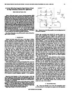
IV. TDR ELECTRONICS AND DATA ACQUISITION Fig. 2 shows a schematic overview of the GREAT electronics and data acquisition system. In this section, the various parts of the system are described. The front-end electronics [constant fraction discriminators (CFDs) and shaping amplifiers] comprises commercial NIM/CAMAC units. The timestamping ADC card is a new design in VXI-D format offering 32 independent channels (14 bits with sliding-scale correction and zero suppression). The ADC conversion and readout time is less than the shaping amplifier’s busy period, so the only counting losses are those due to pileup. A gate is generated for each input either from its associated external CFD or using a software controlled gate matrix, which permits a single input to start a group of gates, for example, one wire in the MWPC to gate itself and its immediate neighbors. The timestamp is recorded for each channel at the start of its gate. In the event of pileup, a second timestamp is recorded to indicate the second firing of the CFD within the original gate period. Qualifiers mark data that is affected by pileup or coincident with a front panel veto input. The timestamping requires the distribution and synchronization of a 100-MHz clock. The clock distribution takes advantage of the facilities built into D-sized VXI, i.e., a 100-MHz clock, ClockSynch signal (to select one edge of the clock), and two STAR lines, which arrive at each slot within a crate with less
LAZARUS et al.: GREAT TRIGGERLESS TOTAL DATA READOUT METHOD
569
card and pattern module has its own SHARC data link. Each link can cope with up to 50 k gates/s on all 32 of its associated ADC inputs. The ADC cards have a diagnostic scaler for missed counts, which indicates whether the SHARC data links and their buffers ever filled to the point of blocking data collection. Data are transferred from the buffers to the event builder over a gigabit Ethernet. Output data from the event reconstruction processors in the event builder are sent to tape for storage using one or more data streams where each data stream corresponds to one class of reconstructed event. In a typical RDT experiment there could, for example, be three streams: one for the prompt recoil-gamma data (gamma ray spectroscopy), one for the emission from the implanted nuclei (decay spectroscopy), and one for events where items from the first two streams have been successfully correlated (recoil decay tagging). V. STATUS The GREAT project is funded and under construction in the United Kingdom. The system design is complete and reported here. The event builder design has started and the electronics design is taking place during 2000/1. Detectors are on order and it is anticipated that the system will be assembled and tested during 2001 for experiments in 2002. Fig. 2. Schematic diagram of the GREAT TDR system’s electronics and data acquisition.
than 2-ns skew. A VME module known as the Metronome controls the clock distribution and maintains synchronization of all the ADCs. A hit pattern VME module provides a method to include patterns in the data stream along with a timestamp. Hit patterns may be either made up of all the bits that are active at some time during the gate input (gated) or transitional. Transitional patterns generate a timestamp whenever an input bit becomes active. A transitional pattern mode may be either gated or free running. Conventional clocked hit patterns are also possible by using a very narrow gate to sample the inputs in gated mode. The operation of the pattern modules is controlled from software with individual enable/disable mask bits for each input. The timestamped data words from the ADCs and the pattern units are each tagged with an address to identify which detector they come from and which signal they represent within that detector. The data items from both ADCs and pattern cards are then sent in time-order via point-to-point data links (SHARC digital signal-processor (DSP) links [7]) into VME cards, where SHARC DSPs receive and buffer the information ready for use by the event builder. Currently, the DSPs are used only for data moving, but there is spare processing capacity that could be used later for real-time diagnostic data histogramming. Every ADC
VI. CONCLUSION The TDR method opens new possibilities for the study of exotic nuclei by allowing the collection of very rare events in a system that simultaneously collects high rate data without dead-time problems. The only losses are due to pileup in the shaping amplifiers, which limits the rate on any one channel. If GREAT works as expected, then in the future TDR will become the architecture of choice for large nuclear structure projects and hardware trigger systems will become obsolete. REFERENCES [1] P. A. Butler, “New developments in electron and recoil decay spectroscopy for studies of exotic and heavy nuclei,” Acta Phys. Polonica B, vol. 31, no. 1, pp. 9–19, 2000. [2] M. Leino, J. Äystö, T. Enqvist, P. Heikkinen, A. Jokinen, and M. Nurmia et al., “Gas-filled recoil separator for studies of heavy elements,” Nucl. Instrum. Meth. B, vol. 99, p. 653, 1995. [3] “VEGA, a proposal for Versatile and Efficient GAmma-detectors,” GSI, Darmstadt, Internal Rep., 1998. [4] K. Helariutta, J. F. C. Cocks, T. Enqvist, P. T. Greenlees, P. Jones, and R. Julin et al., “Gamma-spectroscopy of 192-195 Po,” Eur. Phys. J., vol. A6, p. 289, 1999. [5] P. A. Butler, P. M. Jones, K. J. Cann, J. F. C. Cocks, G. D. Jones, and R. Julin et al., “Electron spectroscopy using a multi-detector array,” Nucl. Instrum. Meth. A, vol. 381, p. 433, 1996. [6] E. S. Paul, P. J. Woods, T. Davinson, R. D. Page, P. J. Sellin, and C. W. Beausang et al., “In-beam Gamma-ray spectroscopy above 100Sn using the new technique of recoil delay tagging,” Phys. Rev. C, vol. 51, no. 1, pp. 78–87, Jan. 1995. [7] Analog Devices, ADSP-2106x SHARC User’s Manual, Mar. 1995, ch. 9.