SAE/AIAA 1999-01-5639
The Implementation of a Conceptual Aerospace Systems Design and Analysis Toolkit Dr. Mark A. Hale and Dr. Dimitri N. Mavris Georgia Institute of Technology
Mr. Dennis L. Carter Air Force Research Laboratory
Copyright © 1999 Society of Automotive Engineers, Inc.
ABSTRACT The Conceptual Aerospace Systems Design and Analysis Toolkit (CASDAT) provides a baseline assessment capability for the Air Force Research Laboratory. The historical development of CASDAT is of benefit to the design research community because considerable effort was expended in the classification of the analysis tools. Its implementation proves to also be of importance because of the definition of assessment use cases. As a result, CASDAT is compatible with accepted analysis tools and can be used with state-ofthe-art assessment methods, including technology forecasting and probabilistic design.
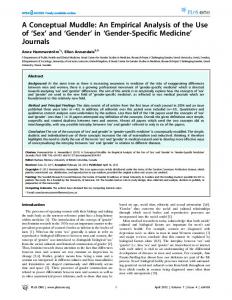
core at the center. The next level consists of domain specific tools using first-order methods of low-fidelity based on a minimal vehicle specification. These analyses possess a high degree of variability in their solutions due to oversimplifications and failure to capture complex phenomenon. To correct problem accuracy and to reduce variability, higher order methods can be used for more detailed analysis. Though more accurate, these methods require more problem setup and analysis time, resulting in the ability to do fewer design iteration. If their integration is successful, the higher order tools give a designer the benefit of using higher fidelity information in earlier design decision-making. Approximations, such as the use of Response Surface Equations, can be used to integrate higher-fidelity modules into a synthesis and sizing framework.1
INTRODUCTION In late 1995, the Air Force Research Laboratory identified the need to form an advanced conceptual aerospace assessment capability for future military aircraft systems. In 1996, a team of investigators from the Air Force Research Laboratory, Aeronautical Systems Center, and Georgia Tech visited the sites shown in Figure 1 in order to determine the state of the art in aerospace systems design and analysis tools. (The company names are listed as they were in 1996.) Site studies quickly led to the modular architecture shown in Figure 2. Synthesis and sizing is, by definition, multidisciplinary and can be visualized as a number of analysis modules linked via a geometric modeling and mission analysis core. The analyses may be integrated with the core with varying levels of fidelity as indicated in the figure. First level guesses, estimates, and historical trends supplement the geometry and mission
•Boeing Defense and Space Group/Seattle •Lockheed-Martin/Fort Worth •Lockheed-Martin/Marietta •McDonnell-Douglas East/St. Louis •McDonnell-Douglas West/Long Beach •Northrop-Grumman East/Long Island •GE Engines, Cincinnati •Allison Engines, Indianapolis •P&W Engines, West Palm Beach •Rockwell, Los Angeles •NASA LARC, Norfolk •NASA AMES RC, Moffett Field •NASA Lewis, Cleveland •NAWC •ATCOM •ASC/XRE, Dayton OH •NAIC, Dayton OH AFRL, Dayton OH OH •Wright Lab, Dayton •DARPA, Washington D.C. •IDA, Washington D.C. •RAND Corp., Santa Monica
Figure 1. Organizations Hosting Study Team in 1996
99WAC-80
Page 2
Noise Noise
Aerodynamics
Economics
Aerodynamics
Economics Geometry
Synthesis Synthesis & & Sizing Sizing Mission Structures
Weights Direct Coupling
Structures
Weights
Conceptual Design Tools S&C
Performance Increas ing S ophis tication and Complexity
Propulsion
Approximations High-F idelity Coupling
Preliminary Design Tools
S&C
Performance
Propulsion
Figure 2. Synthesis and Sizing Architecture
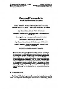
The best accepted tools for each module in this framework were selected at the end of the site visits. Interesting findings about the tools is revealed through the classifications shown in Figure 3. The tools are predominately UNIX-based, coded in FORTRAN, used via command-line interfaces, and supported only on one platform. This code classification reinforces the definition of what is considered to be a “legacy” conceptual design tool. These tools drive the fundamental integration strategy for CASDAT.
Language L anguage
CASDAT MODULES A baseline analysis tool set was selected from those in use by industry and government. These tools were agreed to be indicative of those used in industry and provide acceptable accuracy. The selected tool set and its implementation is referred to as the Conceptual Aerospace Systems Design and Analysis Toolkit (CASDAT). The toolkit is shown in Figure 4. Italicized items were not yet implemented in CASDAT at the writing of this paper.
Interface Interface
C++
C++ JAVA -JAVA 0% - 0%
CC
Non-Graphical
NOISE NOISE Aerodynamics Aerodynamics F OR T R AN
FORTRAN
Platform Platform Windows Windows95
Graphical Graphical
Non-Graphical
VORLAX BDAP WINGDES
Propulsion Propulsion NEPP
Geometry Geometry
Platform Support P latform S upport MacOS
MacOS
FLOPS
>1 Platform >1 Platform
Structures Structures ASTROS
RAM
CASDAT
Installation Installation PIPSI
Mission Mission UNIX
UNIX
FLOPS
One Platform
1 Platform
Weights Weights
Figure 3. Synthesis and Sizing Tool Classifications
FLOPS LTV
Economics Economics MALCCA
S&C S&C HASC
Figure 4. Conceptual Aerospace Systems Design and Analysis Toolkit
99WAC-80
CASDAT FRAMEWORK Several candidate computational frameworks for implementing the modules were also identified during the site visits. The Intelligent Multidisciplinary Aircraft Generation Environment (IMAGE) developed at the Georgia Tech Aerospace Systems Design Laboratory was selected as the framework for CASDAT because of its emphasis on technology assessment and design method integration, distributed simulation capability, and it is freely available.2 IMAGE is a multi-media based, designer-oriented computational framework. It is presently available for UNIX systems and includes database functionality, process management, and advanced design functionality. The use of this system is particularly useful for the CASDAT initiative because it has built-in methods for integration of typical analysis tools; those represented in Figure 5 (following page). A wizard is shown in Figure 5 that prompts the user for information pertaining to the analysis tool and automatically creates a program module in CASDAT. CASDAT was originally envisioned as a distributed design system in which the selected tools could be executed in a heterogeneous environment, necessitated because of the reliance on legacy tools which exist only on single platform. As the contract progressed, all of the legacy analysis tools that were to be integrated were available on the SGI platform. The geometry modeler RAM is only available on the SGI platform and thus dictates the platform unless the end-user substitutes another modeling tool.
MODULE INTEGRATION The characteristics of the legacy analysis tools as described in the previous section lend the tools to standard practices for tools integration in which the tool execution is modeled, called wrapping.3 The most important integration design decision was to determine the degree of data fidelity that would be modeled for each tool. A detailed variable level description was used for these the geometry model and mission analysis capability in synthesis and sizing because of the importance of their data for other tools and for design tradeoffs.4 The other tools were modeled at a higher level because they are used as supporting tools for the sizing and synthesis core tools. The details of the modeling are described next. File Level Modeling All of the legacy analysis tools used in CASDAT are filebased applications. They read formatted or namelist input files and write formatted output files. File pointers were configured in the CASDAT database to refer to user specified files for each analysis tool. Pointers are used rather than reading the files directly into the database in order to maximize databases efficiency and portability. IMAGE includes file archival routines to catalogue and retrieve files from the user’s operating environment. These routines are particularly useful during automated and iterative applications where it is desired to preserve output information from one analysis
Page 3 to the next. These file references can easily be changed by the end-user to integrate problem specific data. Variable Level Modeling Specific parameters found in the input and output files of the geometry modeler RAM and the mission design and analysis tool FLOPS were modeled in addition to the files themselves. The geometry variables include such things as wing span and chord and fuselage length and diameter. The mission parameters include design variables such as range and cruise speed and performance metrics such as approach speed and landing field length. Since these variables have been modeled in CASDAT, they can easily be passed to other tools or can be manipulated by designers directly during design studies. A degradation of computational performance does occur when variables are modeled because the variables must be substituted and extracted from files when the tools are executed. IMAGE does contain built-in utilities to aid in this process.
TECHNOLOGY ASSESSMENT A critical function for CASDAT is the rapid assessment of technologies on aerospace systems. The use cases shown in Figure 6 can be derived from this need. The user may desire to select from existing baseline aerospace systems, collect sub-systems into a new system, or create a new baseline. Henceforth, new technologies will be applied using a structured approach called Technology Impact Forecasting.5 Analyses must be formed so that impact can be assessed. These analyses may be pre-existing for the baseline system, or may require extensive development and integration into the CASDAT framework for new, revolutionary technologies. The user may interact with a set of standardized methods existing within the IMAGE system for system assessment. Finally, system assessment information must be catalogued and disseminated. A management structure exists in CASDAT to facilitate common tasks defined by the use cases. These tasks include database manipulation, for example separating a geometry file into individual variables and inserting them into the database, and execution, such as the execution of a response surface equation for a vehicle. A number of design assessment capabilities are available to CASDAT through the use of IMAGE. These are shown in Figure 7. Each of these capabilities is implemented through an interface that guides the user in making an assessment. Several advanced design techniques are required as a designer employs these methods to solve problems. These include: • Approximation through the use of Design of Experiments • Probabilistic analysis through the use of Monte Carlo analysis or Fast Probability Integration • Alternative identification through the use of Morphological Matrices The assessment interfaces have built-in functions for accessing these methods.
99WAC-80
Page 4
Start
Name
Input
Executable
Creation
Figure 5. DATCOM Module Integration into CASDAT
Output
Finish
99WAC-80
Page 5 Start Start
Add Add Technologies Technologies
Form Form Analysis Analysis
Assessment Assessment
Document Document
New New Design Design Existing Existing Design Design
et ho ds M
rc hi te ct ur e rA od ul a
Te ch no
lo gy
M
Im pa ct Fo re ca s
tin g
Merge Merge Designs Designs
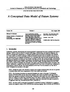
Figure 6. CASDAT Use Cases An example of the parameter study interface using a notional F-16 baseline is shown in Figure 8. System parameters defined in the database are varied in the window in the upper left. A synthesis and sizing tool is executed in the background and results in the corresponding three-dimensional plots appearing in the lower right. The interface can be used to quickly change parameter ranges and executing the analyses. Analysis tools can be interchanged with other tools available from the standard modules of CASDAT through simple drag and drop operations.
automatically updated during the use of iterative design procedures. Accuracy is required because the model is translated into various formats depending on the disciplinary analysis tools to be employed. Existing conceptual modelers often fail to consider component intersections when calculating geometric information and few account for internal arrangements during sizing. •
Disciplinary design software file formats are difficult to integrate. The format and parameterizations of disciplinary analysis tools were found to be strikingly disparate. Their integration often required translators that resulted in loss of information or could function only in a single direction. FORTRAN namelists were found in several analysis tool input files but others required large formatted files for passing array information not handled easily by namelists.
•
Revolutionary concepts are difficult to analyze using conceptual tools. The analysis tools incorporated into the CASDAT modular architecture represented the best of present day tools. However, physics-based programs are still needed to handle the intricacies of revolutionary configurations.
Definition
Manager Manager
High-level configuration and technology application
Problem Problem Study Study Parameter Parameter Study Study
Detailed examination of vehicle performance
Sensitivities Sensitivities
Examination of system feasibility based on design variables
Probabilities Probabilities
Prediction of performance in presence of uncertainty
Forecasting Forecasting
Examination of system responses with respect to technology factors
Figure 7. Assessment Capabilities Available in CASDAT
LESSONS-LEARNED Several lessons-learned can be drawn from implementing and exercising the CASDAT framework. Some pertain to the formation of the analysis tool framework and others outline specific shortcomings of conceptual analysis tools. •
Modules should be integrated by task or functionality and not by programs. Often, frameworks are measured by the number of analysis tools that are integrated. More importantly, the capability to perform userdefined tasks should be considered instead.
•
An accurate parameterized geometric modeler is needed. There is an important reliance on the geometry model during the design process. The model must be parametric so that the configuration can be
CONCLUSION The Conceptual Aerospace Systems Design and Analysis Toolkit (CASDAT) represents a baseline technology assessment capability for the US Air Force. CASDAT was carefully constructed from the best available analysis tools using a modular architecture. As a result, designs and technologies can be rapidly synthesized and studied. The IMAGE framework, used in the implementation, proved useful in meeting the design goals because it incorporated several advanced design method capabilities. The framework also has the facilities for rapid analysis tool modeling and integration so that CASDAT can be extended easily by the end user to incorporate additional analysis tools.
99WAC-80
Page 6
Figure 8. Parameter Study Capability
99WAC-80
Page 7
ACKNOWLEDGMENTS
REFERENCES
The authors wish to acknowledge Mr. Dennis Carter of the Air Force Research Laboratory for research support for this work under Contract Number F33615-95-D-3800, Delivery Order #5. Work done by Mr. Daniel Tejtel in the base module implementation as a graduate research assistant at the Georgia Tech Aerospace Systems Design Laboratory is also acknowledged. The NASA Langley and Ames Systems Analysis Branches are acknowledged for their assistance in providing and supporting several of the analysis tools used in CASDAT.
1 Box, G.E.P., Draper, N.R., Empirical Models Building and Response Surfaces, John Wiley & Sons, Inc., 1987 2 Hale, M.A., Craig, J.I., Mistree, F., Schrage, D.P., "DREAMS and IMAGE: A Model and Computer Implementation for Concurrent, Life-Cycle Design of Complex Systems," Concurrent Engineering: Research and Applications, vol. 4, no. 2, pp. 171-186, June 1996. 3 Hale, M.A., Craig, J.I., "Techniques for Integrating Computer th Programs into Design Architectures," 6 AIAA/NASA/USAF/ISSMO Symposium on Multidisciplinary Analysis and Optimization, Bellevue, WA, September 4-6, 1996. AIAA-96-4166. 4 Hale, M.A., Craig, J.I., and R. S. Peak, “On the Role of the Geometry Model in Engineering Design,” CATIA Solutions Magazine, Volume 3, Number 3, May/June 1999. 5 Mavris, D.N., Bandte, O., DeLaurentis, D.A., "Determination of System Feasibility and Viability Employing a Joint Probabilistic Formulation", 37th Aerospace Sciences Meeting & Exhibit, Reno, NV, January 11-14, 1999. AIAA 990183.
CONTACT Dr. Mark A. Hale Georgia Institute of Technology School of Aerospace Engineering Atlanta, GA 30332-0150 (404) 894-9810 (404) 894-6596 FAX
[email protected] www.asdl.gatech.edu Dr. Dimitri N. Mavris Georgia Institute of Technology School of Aerospace Engineering Atlanta, GA 30332-0150 (404) 894-1557 (404) 894-6596 FAX
[email protected] www.asdl.gatech.edu Mr. Dennis L. Carter, P.E. Aerodynamic Configuration Branch AFRL/VAAA 2130 Eighth St.,Ste 1 WPAFB, OH 45433-7542 (937) 255-8298 (937) 255-8377 FAX
[email protected]