Master's the- sis, Department of Computer Science, Technical University of Denmark, August 1994. In English. [6] I. Klotchkov and S. Pedersen. A codesign case ...
The Importance of Interfaces: A HW/SW Codesign Case Study Dan C. R. Jensen�
Jan Madsen
Steen Pedersen
Department of Information Technology Technical University of Denmark
Abstract This paper presents a codesign case study in image analysis. The main objective is to stress the importance of handling HW/SW interfaces more precisely at the system level. In the presented case study, there is an intuitive and simple HW/SW interface, which is based upon the functional modules in the application. However, it is found, that this seemingly sound choice caused a number of practical problems and sub-optimal solutions during the implementation of the proto type system.
1. Introduction In this paper we will concentrate on the interface problems, as they evolved during the implementation of a HW/SW codesign case study for image analysis. The application was chosen both for its speed up potential, when realised as a mixed HW/SW system, and from a seemingly well defined separation in modules with precise interface specifications. The intention was to use this realistic and computationally challenging example as a relative simple test bench in the development of codesign methods and tools [7, 8, 12, 13]. Though the design and implementation of the HW using ASICs indeed was challenging, a considerable part of the time spent in realising the system was, as this paper will show, used dealing with interfaces. The objectives of the paper are therefore: �
To stress the importance of being able to handle HW/SW interfaces.
�
To argue for the need for a methodology, which support interface modelling and synthesis from abstract specification to realisation, in analogy to the methodologies used for HW and SW development.
� Dan C. R. Jensen is now with: GN Danavox AS, M˚arkærvej 2A, DK2630 Taastrup, Denmark
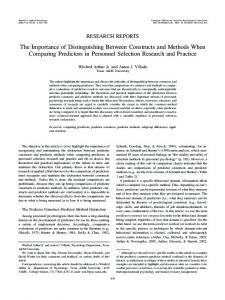
2. The optical flow case study At the Department of Information Technology1 at the Technical University of Denmark a research framework dealing with different aspects of codesign has been carried out for the last three years. The case study presented in this paper is one of the larger experimental works within this framework, and it is carried out together with the image analysis group at the Department of Mathematical Modelling2, IMM, also at the Technical University of Denmark. The objective was the realisation of a highly effective implementation of an inbetweening algorithm within the field of optical flow [10]. Using this in-betweening algorithm, it is possible to calculate 10 new images between each of the 48 frames in a 24 hour sequence of satellite weather images. This is then used to present a smooth animation of the weather dynamics in the weather forecasts. The initial implementation of the system was done at IMM as a C-program. The in-betweening algorithm consists of three well separated parts with well defined interface, see figure 1 and table 1. Input 1
Image sequence
3D-
Local
Global
convolution
optimisation
optimisation
(1 week)
2
(7 min.)
A
B
3
(17 min.)
C
Output 4
Velocity field
Figure 1. Overview of the in-betweening algorithm modules. The four interfaces and the three functional units, A, B and C, are described in the C-program. The computational complexity is illustrated by the actual run time of this Cprogram, which is shown for each module.
The characteristics of three functional parts, A, B, and C, are as follows: 1 http://www.it.dtu.dk 2 http://www.imm.dtu.dk
Interfaces Data type Data set size 8 bit pixels 12 MByte 32 bit words 604 MByte 4 and 8 bit words 63 MByte 8 bit vectors 12 MByte
ID 1 2 3 4
Table 1. Definition of data types and data set sizes for the four interfaces in figure 1.
A: 3D-convolution. The convolution is for a single result pixel, Ch;v;t , given by the equation
C
h;v;t
=
X X XP n
n
n
=?n y=?n z=?n
+x;v+y;t+z � Kn+x;n+y;n+z
h
to be carried out. Therefore, a 3D-convolution system based upon a dedicated hardware convolution engine had to be implemented [5].
3. System design considerations It was decided to follow a data path design strategy, primarily to ensure the high system throughput. The 3Dconvolution part was chosen for HW implementation as shown in the overview of the system in figure 2. Image sequence Input
Output
x
Each pixel in the result is the sum of the products of the neighbouring pixels, Px;y;z , and a set of constants, Kx;y;z , called the kernel. Both the kernel size, 2n + 1, and the dynamic range of the individual kernel values should be as large as possible. In the target application, in-betweening of weather satellite images, there is a image sequence consisting of 48 frames, each having 512�512 eight bit pixels. To calculate the globally optimised optical flow, 12 different convolutions using a 15�15�15 kernel, (n = 7), over this data set must be performed [5]. B: Local optimisation. After the convolutions using the 12 kernels, the most dominant local flow velocity values are found, using an eigenvalue and eigenvector analysis. This produces two sets of 16 bit normal velocity vectors and 4 bit weights, a total of 40 bits per pixel [4]. C: Global optimisation. All the local dominant flow vectors are evaluated in one large matrix of equations, where each pixel contributes with to rows and two columns, to ensure the coherence of the flow field [11]. The final part, the creation of the the in-between images, is now done directly from the velocity field and the original image sequence. In the pure software solution, which is used as the definition of the application, this implementation of the algorithm using the sequence of 48 input frames and 12 kernels requires one week of CPU time on a high end workstation. The aim of the case study is to reduce this time to less than 30 minutes using a combined HW/SW solution, which is a speed up of around 300 times. It is obvious from figure 1, that the 3D-convolution is the prime candidate for a HW realisation. However, as the optimisation parts still requires around 25 minutes in the SW realisation, there is only 5 minutes left for the 3D-convolution. Basically, this requires 5�1011 multiply-add operations performed in 5 minutes, or in other words 1,7�109 multiply-add operations/second has
1
4
New image sequence
1
High end workstation B, C
3D-Convolution system A
2
SW
HW
Figure 2. Overview of the 3D system with identification of the three functional units and interfaces.
In the more detailed design process the major problems turned out to be memory and communication bandwidth. From the 12 Mbyte of input data, the 3D-convolution module produces 604 Mbyte of output. Each pixel in the input sequence is used in 40.500 computations with the actual convolution parameters. This requires the use of a number of local memories to off load the workstation, parallelisation and pipelining in the design of the computational units, and an advanced caching scheme to feed these units in order to meet the computational requirements. Beside from obtaining the required performance, a number of additional requirements were posed on the implementation of the system: �
A general and well known communication between the 3D-convolution engine and the workstation should be used, i.e. we did not want to build a system, which was tied to one specific type of workstation.
�
The interface between the workstation and 3Dconvolution engine must be scalable, i.e. if a higher bandwidth is required, this must be achieved by changing from one standard network technology, including boards and drivers, to another standard technology. We did not want to invent a new communication technology.
�
As much of the system as possible should be realised using off-the-shelf products.
The industrial VME-bus and Motorola 68040 CPU board running the OS/9 operating system was chosen as the best
way to satisfy these requirements. The resulting system setup is shown in figure 3. DRAM
TRAN
CACHE
VMEbus System Ethernet
M68040
VMEbus
Boards
SW
interface
ASICs Control
ASIC
ASIC
ASIC
A
Interface
HW
CTRL
B, C
interface
Driver
interface
Driver
interface
Memories
KERNEL
Workstation
TMP
Figure 3. The 3D system with the VME-based 3D engine on the VMEbus boards and a more detailed interface presentation.
RES
It is obvious from this figure, that the well defined and simple HW/SW interface interpretation, which is used at the system definition level in figure 2, is not at all adequate at this next level in the design process. Although made from of-the-shelf parts, the implementation required more attention than presumed, simply by the time needed to unpack, install, and get these parts working together. However, the system design requirements regarding scalability are met by this implementation, e.g. if the bandwidth requirements of interface 2 cannot be met by the chosen 10 MBit/s Ethernet interface, this can be changed to a 100 MBit/s FDDI interface with only little additional effort in the implementation process.
4. 3D convolution engine A number of possible implementations of the convolution engine were analysed, [2, 5, 14, 15], and the chosen design, together with some of the module data, is shown in figure 4. As indicated in the figure, the convolution engine is based on three ASICs, each having 75 processing elements (PEs). These elements consists of a fast multiply-add block with pipeline registers and two sets of kernel registers. The PEs are arranged in a systolic structure [9], which makes one ASIC produce 2.3�109 multiply-add operations/second, when clocked at 30 MHz. One ASIC contains 384.000 transistors and the computational performance has been verified by measurements [1]. As the system is pipelined, flushing can not be avoided, but by using two banks of kernel registers an efficiency of more than 97 % can be obtained. The control functions in the 3D-engine ranges from decoding and executing instruction codes, such as read pixel data from VMEbus to local DRAM memory or start computations, to managing the detailed timing of the
ASIC
2D convolution ASIC
CACHE 15 kb 20ns 2-p RAM
KERNEL 256 kb SRAM RES
4 Mb 70ns SRAM
CTRL
7 EPLD 7128 PLDs
TMP
4 Mb 35ns SRAM
DRAM
64 Mb DRAM
TRAN
256 kb SRAM
Figure 4. Overview of the data path structure and the memory structure and sizes of the 3D-engine. The prototype system is implemented using 7 18 26cm2 PCBs.
�
read/write signals for the physical memory devices. This controller was from the beginning chosen to be hardwired, i.e. implemented in a FPGA on one of the boards. However, the detailed design showed, that this task did not fit in any of the available FPGAs. If the FPGA had the room for all the functions, the required speed could not be obtained. The result was then to make a controller hierarchy and use 7 PLDs for the complete controller shown in figure 4. The 3D-convolution prototype has been fully implemented and tested. This includes the design and test of the ASICs, the memory structures, and the controller as shown in figure 4. The prototype also includes the communication between the workstation and the VME-based system. This was implemented as a client/server system using TCP/IP and sockets. In this environment, the programmers interface to the 3D-convolution system is a C-library with function calls. The prototype system has also been tested using a 3Dconvolution application from a volume data set from a medical image analysis application [3]. The HW/SW prototype system here showed a speed up of more than 100 times compared to the SW implementation when using the volume
data set, which consist of one 15�15�15 kernel and 256 images of 512�512 pixels.
5. Interface discussion Having established a prototype on which experiments can be carried out, we are able to discuss the applicability of the selected interfaces. From the beginning of the design process, it was decided to keep the initial structure of the specification in order to have a simple and well defined HW/SW interface. However, as outlined in this paper, this seemingly simple interface turned out to be quite complicated to implemented, mainly due to the bandwidth requirement and protocol conversions, i.e. getting data from the workstation to the VME-bus. It turns out that the bandwidth requirement of 604 Mbyte can be reduced to 302 Mbyte by simply adding a square root function to the HW [6]. I.e. Bandwidth requirement could be reduced by moving functionality from SW to HW. The interface to the HW performing the convolution, was initially controlling a simple stream of data, in order to feed a pipelined and highly parallelised architecture. However, due to the limitation of the bandwidth, sophisticated memory structures had to be introduced, turning the simple data flow oriented architecture into a rather complicated architecture, in which the data streams between different memory modules (temporary storage, cache, etc.) and the ASICs have to be controlled at a very detailed level. I.e. the controller which initially looked like a simple ring-counter, turned out to be a rather complicated hierarchical controller, in which a top controller controls the execution and ordering of a number of specialised sub-controllers. This controller design could be simplified by moving the top controller from HW to SW. This would also make the top controller easily modifiable. The question is then whether the SW should be placed in the work station, in the CPU of the interface, or in a dedicated CPU on the HW board. In any case, it would have been interesting to try out these alternatives in a system level model.
6. Lessons learned In the following we will try to summarise the lessons learned regarding the selection and implementation of the HW/SW interfaces. The case study presented in this paper has demonstrated an important aspect of the relation among different levels of abstraction. I.e. the best module structure at the specification level, which for the case study expressed a simple and well defined HW/SW interface, may not reflect the best structure at the implementation level, no matter how simple and well defined it may seem.
Many of the interface problems stems from the lack of having an accurate system model which could be analysed and refined along the design process. The actual prototype was the first executable “model” of the complete system. For modelling the HW (ASIC as well as off-the-shelf components) a language like VHDL could have been used. However, the effort to describe and model the off-the-shelf components could easily be as large as implementing the system. Thus, the case study has demonstrated the need for being able to analyse and refine interface structures in order to foresee potential problems at the lower levels in the design process. We believe that what is needed, is a methodology which will allow the interfaces to be developed concurrently with the development of HW and SW.
7. Acknowledgements The work presented here is part of the Codesign research framework, which is funded by the Danish Technical Research Council.
References [1] J. P. Brage and S. Pedersen. The case study homepage: http://www.it.dtu.dk/˜case3d. 1994. [2] J. P. Brage and S. Pedersen. A case study in architectural and technological trade-offs. NORCHIP-94, pages 78–85, November 1994. [3] M. Bro-Nielsen. Medical Image Registration and Surgery Simulation. PhD thesis, Department for Mathematical Modelling, Technical University of Denmark, 1996. Submitted. [4] A. R. Henriksen. Analysis and realisation of in betweening algorithm. Master’s thesis, Department of Computer Science, Technical University of Denmark, July 1995. In Danish. [5] D. C. R. Jensen. 3D convolution VLSI ASIC. Master’s thesis, Department of Computer Science, Technical University of Denmark, August 1994. In English. [6] I. Klotchkov and S. Pedersen. A codesign case study: Implementing arithmetic functions in fpga’s. Proceedings of ECBS’96., pages 389–395, March 1996. [7] P. V. Knudsen and J. Madsen. Aspects of system modelling in hardware/software partitioning. Proceedings of 7th IEEE International Workshop on Rapid Systems Prototyping, RSP’96, pages 18 – 23, June 1996. [8] P. V. Knudsen and J. Madsen. Pace: A dynamic programming algorithm for hardware/software partitioning. Proceedings of 4th International Workshop on Hardware/Software Codesign, Codes/CASHE’96, pages 85 – 92, March 1996. [9] S. Kung. VLSI Array Processors. Prentice Hall, 1987. [10] R. Larsen. Estimation of Visual Motion in Image Sequences. PhD thesis, Institute for Mathematical Modelling, Technical University of Denmark, 1994.
[11] J. Lund-Larsen. Solutions to large systems of linear equations. Master’s thesis, Department of Computer Science, Technical University of Denmark, January 1996. In Danish. [12] J. Madsen and J. P. Brage. Codesign analysis of a computer graphics application. Design Automation for Embedded System, 1(1-2):121 – 145, January 1996. [13] J. Madsen, J. Grode, P. Knudsen, M. Petersen, and A. Haxthausen. Lycos: the lyngby co-synthesis system. Design Automation for Embedded Systems, 1997. to appear. [14] J. E. Poulsen. Design of high speed VLSI circuits. Master’s thesis, Department of Computer Science, Technical University of Denmark, February 1994. In Danish. [15] S. R. Rasmussen. Synthesis of a 3D convolution algorithm from a VHDL description. Master’s thesis, Department of Computer Science, Technical University of Denmark, February 1994. In Danish.