Autonomous Robots 8, 53–69 (2000) c 2000 Kluwer Academic Publishers. Printed in The Netherlands. °
The Inchworm Robot: A Multi-Functional System KEITH KOTAY AND DANIELA RUS Dartmouth Robotics Laboratory, Department of Computer Science, Dartmouth, Hanover, NH 03755
[email protected] [email protected]
Abstract. We wish for robots to manipulate objects and move flexibly in three-dimensional spaces. We describe a robot that can move on a web of surfaces oriented around arbitrary directions in three-space and a set of control algorithms that implements motion in three-dimensions. The robot can manipulate objects in three dimensions while moving, by using the same set of physical resources and control algorithms. This robot is an inchworm-like robot with a simple, modular, and flexible design. Finally, we discuss our experiments. Keywords:
1.
inchworm robot, three-dimensional navigation, three-dimensional manipulation, minimalism
Introduction
We wish for robots to navigate and manipulate objects flexibly and autonomously in three-dimensional environments, regardless of the presence, absence or direction of gravity. Such robots must have the ability to propel themselves along any direction in three-space in a controlled way. Consider a task in which a robot is to climb up a complicated structure such as the Eiffel Tower, for inspection. The Eiffel tower is made of a web of metal bars. The bars are almost flat, they have varying lengths and directions, and they are oriented arbitrarily in three-space. A robot executing this task requires several skills: the robot should be able to climb vertically, the robot should be able to move inverted, it should be able to travel on arbitrarily oriented surfaces and avoid obstacles, and it should be able to make transitions between adjacent surfaces (bars). We wish to do this task with an autonomous robot. We can view this task as a navigation problem in a three-dimensional space. The objects in this space are near-flat (planar or smooth with shallow curvatures) and they vary in size and orientation. The robot does not have geometrical models of the shape, nor mechanical models of their frictional properties. Furthermore, the robot does not assume anything about the size of the gravitational constant or about the direction of gravity. We assume however that the objects in the world are ferrous, so that
the robot can use magnetic forces to attach to them. (We discuss alternatives to electromagnets as an attachment mechanism in Section 3.1.) Example worlds include the Eiffel tower, space stations, ships, metal bridges, radio towers, skyscrapers, nuclear reactors. Example applications for a robot endowed with the skill to navigate on such objects are inspection, fire-fighting, construction and repair tasks. In this paper we describe the Inchworm robot we have designed and built as an experimental platform for algorithms for three-dimensional navigation and manipulation. The Inchworm is a light robot designed with a minimalist philosophy (Donald et al., 1997a): we looked for the simplest mechanical and control design that would support three dimensional locomotion. Minimalism (Donald et al., 1997a) provides an interesting framework for reducing the complexity of robot algorithms. A minimalist algorithm for task A that does not use resource B proves that B is inessential to the information structure of task A. In designing this robot we drew inspiration from biology. We studied the motions of inchworm caterpillars. Inchworms (also called loopers) move with a looping movement in which the anterior legs and posterior legs are alternately made fast and released (Opler, 1994). The strong grip allows inchworms to attach themselves to arbitrarily oriented objects. The alternation of fastening enables a propelling motion.
54
Kotay and Rus
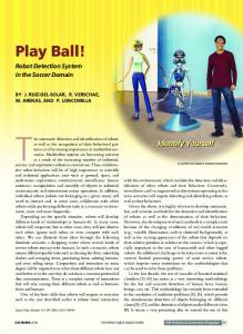
Figure 1. The Inchworm robot. The body of robot consists of four links. The first and last link of the robot comprise the feet. Each foot has two 1-inch electromagnets attached to it. The robot has one front IR sensor and a pair (IR sensor, contact switch for touch sensing) attached to each electromagnet. The robot has three actuators attached to the three joints visible in the plane of the image. A fourth actuator attached to the back foot allows the robot to pivot in and out of the plane of the image.
This simple strategy gives inchworms the mobility to move stably on arbitrarily oriented surfaces. We have engineered an Inchworm robot that is a light linear structure made of four links. The end links are the robot’s two feet (see Fig. 1). Electromagnets placed on the feet allow the robot to attach to arbitrarily oriented surfaces, much like the loopers. Similarly, the robot alternates current to the two electromagnetic feet to simulate the inchworm propelling motion. The Inchworm robot supports an O(1) greedy navigation strategy based on the idea of climbing over the obstacles to reach the goal rather than the usual way of searching for paths around obstacles. The Inchworm robot uses a small set of task-level primitives for moving along planes of arbitrary orientations and for making transitions between such planes. These tasklevel primitives can be composed to generate on-line navigation algorithms in three dimensions and manipulation algorithms. Thus, the Inchworm belongs to the class of mobipulator robots (Mason et al., 1999, to appear; Nilsson, 1984; Pai et al., 1994; Donald et al., 1997; Xu et al., 1994), which are designed to explore the connections between locomotion and manipulation. While several other papers have examined the connection between locomotion and manipulation
(Mason et al., 1999, to appear; Nilsson, 1984; Pai et al., 1994; Donald et al., 1997a; Xu et al., 1994), this robot is different in that it treats manipulation and locomotion identically at the control level. All locomotion and manipulation algorithms are composed from the same set of task-level primitives. In our lab, we built two Inchworm robots. Our simple and modular design is lean in sensors and actuators but is extensible: right now each robot consists of four identical links connected by a simple joint. The robot is equipped with a camera, 5 IR proximity sensors and 4 discrete touch sensors attached to the feet, and moves compliantly. This design is extensible to any number n of links. We advocate an extensible minimalist approach to robot architectures for two reasons. First, since the size of an Inchworm step is proportional to the total length of the robot, an extensible architecture impacts the speed and efficiency of navigation. This is particularly suited to applications where there is no gravity, as supporting the weight of a robot on magnets no longer becomes an issue. Second, extensible robots have increased functionality. For example, we are planning on building four more Inchworm robots and combining them into a six-legged walker. Such a robot will be able to travel on non-ferrous and nonsmooth terrains. The Inchworm robot can propel itself on arbitrarily oriented surfaces in the absence of geometric models. Its motions are compliantly controlled on-line. The control algorithms are simple, compliant, online, adaptive, and reliable. In our lab, the Inchworm walked hundreds of steps over filing cabinets, doors, and closets. The robot also walked up a fire escape outdoors. The Inchworm robot can also manipulate objects while navigating over three dimensional surfaces. The basic manipulation skills we have developed are pushing an object (moving on a flat surface or climbing on an incline) and pulling an object on a flat surface. In our lab the robot performed these operations with great reliability. The robot was also capable of transitioning between a pure navigation mode to a navigation and manipulation mode. In this paper we show how to accomplish this using the same basic control and design paradigms to enable both manipulation and locomotion. This is a basic form of multi-functional robotics, in which, as in biological systems, the same set of physical resources can be used in a different manner, for different tasks, by employing different control pathways or control algorithms.
The Inchworm Robot
2.
Related Work
Our work draws on previous experiences with navigation algorithms (Latombe, 1991), designing biologically-inspired robots, and designing minimalist robot systems (Donald et al., 1997a, 1997b). Related work on biologically-inspired robots includes Brooks (1989), Leventon (1993), Hirose et al. (1991), Fernworn and Stacey (1996), Desai et al. (1995). Brooks (1989) proposes insect intelligences. Leventon (1993) describes the design by Kerley of a caterpillar robot capable of a crawling movement similar to the horizontal gait of our robot. The robot is also capable of climbing, but its flexibility is limited, making obstacle avoidance difficult. Fernworn (1995) describes an inchworm robot capable of linear motions on horizontal surfaces. Burleigh Instruments developed and patented an Inchworm Motor whose funtionality resembles the movement of an inchworm caterpillar (see http://www.burleigh.com/Pages/inchtech.htm for details). Related work on climbing robots include Madhani and Dubowsky (1992), Neubauer (1994), Hirose et al. (1991), Gradetsky and Rachkov (1990), Carrara and de Paulis (1989), Nishi (1992), Chernousko (1990), Xu et al. (1994). Dubowsky (Madhani and Dubowsky, 1992) describes a three-legged robot that climbs between two ladders. Nishi (1992) describes a biped walking robot configured as a pendulum that uses a suction device for attachment and is capable of linear motions and surface transitions. Hirose (Hirose et al., 1991; Nagakubo and Hirose, 1994) describes a quadruped robot that uses suction cups for attachment and can climb on straight surfaces (vertically and horizontally) and make transitions between surfaces with joint angles of 90 degrees. This robot is much heavier than ours (99 pounds vs. 1 pound). Xu et al. (Xu et al., 1994; Xu and Ueno, 1994) describe an inchworm-like robot that uses grippers as attachments to move along a space station truss. Our robot is different than the previous climbing robots in that it is much smaller, lighter, uses less sensing, needs less workspace to operate and it can handle web structures, as well as solid walls. However, our robot requires a ferrous surface while the robots proposed in Nishi (1992) and Hirose et al. (1991) use suction cups and the robot proposed in Xu et al. (1994) use grippers—thus these other robots do not have material dependencies. Finally, the robots (Nishi, 1992; Hirose et al., 1991) depend on smooth surfaces, while ours can handle porous surfaces.
55
Related work on the exploration of the connections between locomotion and manipulation include Mason et al. (1999, to appear), Nilsson (1984), Pai et al. (1994), Donald et al. (1997b), Xu et al. (1994). In Rus and Kotay (1999), a modular extensible robot architecture that support multiple modalities of locomotion is described. We were inspired by the control and kinematic analysis of Kelly and Murray (1994), Chen et al. (1994), Chirikjian and Burdick (1991) in the design and kinematic analysis of our system. 3. 3.1.
The Inchworm Robot The Mechanical Components
The Inchworm is a biologically-inspired minimalist robot, designed to imitate the movements of the inchworm caterpillar. This functionality was achieved by creating a light, linear structure made of four sections. The sections are linked with three joints providing three degrees of freedom (see Fig. 1). These joints allow the Inchworm to extend and flex. The first and fourth sections are the feet of the Inchworm. These sections contain the attachment mechanisms, equivalent to the legs and protolegs of the inchworm caterpillar, which allow the Inchworm to adhere to the surface it is traversing and provide the anchoring force needed to support the Inchworm walking motion. A fourth degree of freedom is provided by a pivot joint which allows the body of the Inchworm to rotate relative to the attachment mechanism of the rear foot. This allows the robot to turn. The actuators for the joints are servomotors (Airtronics 94739 Proportional Retract Servo) designed for use in radio controlled aircraft. The 94739 servo weighs 50 grams and produces 5.3 kg cm of torque. This high torque-to-weight ratio is essential to support the full range of motion (especially the surface-to-surface transitions) we wish the robot to have. The weight of the Inchworm is 566 grams. When fully extended, the length of the robot is 330 millimeters and its height is 80 millimeters. When fully contracted, the length of the robot is 175 millimeters and its height is 160 millimeters. The speed of the robot is 0.75 meters/minute. The attachment mechanism of the robot is comprised of electromagnets. There are two 12-volt electromagnets per Inchworm foot, arranged in-line with the body of the Inchworm. These electromagnets provide enough force to securely anchor a foot and support the weight of the robot when the other foot is completely
56
Kotay and Rus
extended. This enables our robot to utilize its entire range of motion. We chose electromagnets because they are easy to use and provide a large amount of attachment force in a small package. However, this choice restricts the motion of the robot to steel surfaces. The modular design of the robot makes it easy to replace the electromagnetic modules (mechanical, electronic, and control) with modules that utilize suction cups or grippers. The Inchworm has three types of sensors: touch sensors, infrared proximity sensors, and a small camera. The touch sensors are Omron model EE-SA105 phototransistor optical switches with spring actuator. Two of these sensors are mounted on each foot of the Inchworm, one in front of the forward electromagnet and one behind the rear electromagnet. The touch sensors are used to establish firm contact of the electromagnets with the surface being traversed. The touch sensors also are used to indicate error conditions such as contact with a surface when it is not expected. The infrared proximity sensors are Omron model EE-SF5 reflective photomicrosensors. These sensors are used to implement compliant movements along a surface. Five infrared proximity sensors are used on the Inchworm, four mounted adjacent to the touch sensors oriented downward in order to monitor the surface, and one mounted on the front of the Inchworm facing forward. The camera is a small 1.125 inch monochrome camera with a 6.5 mm lens. The camera is mounted on the front foot of the robot and it points forward. The power source for the Inchworm consists of two lead-acid batteries. An 8-volt battery is used to power the servomotors and the electronics. The electromagnets are powered by a 18-volt battery. The batteries are not located on the body of the Inchworm due to weight constraints. Thus, the current use of electromagnets presents a limitation for using this robot on high structures: the Inchworm Inchworm must be connected to these components with a tether, which increases the weight of the system. We are currently exploring other means of powering this robot, for example with solar cells or a small gas-combustion engine. 3.2.
The Electronic Components
Low-level hardware control of the Inchworm is achieved by an on-board 8-bit PIC16C73 microcontroller. This microcontroller generates the pulse width modulation signals used to control the servomotors and also reads the robot’s sensors. Higher-level control is
performed by a remote workstation which communicates with the microcontroller via a 38.4k baud serial link. This gives the Inchworm the properties of a remote-brained system, as outlined in (Inaba, 1993). The servomotors (e.g., the actuators) are controlled by varying the width of a positive electronic pulse between 1 and 2 milliseconds in duration. This pulse must be repeated every 20 milliseconds. Each servo is controlled by a 9-bit value output by the PIC16C73 microcontroller. We use 308 different servo positions, which results in a rotational resolution of 0.85 degrees. Electromagnet control is accomplished by a integrated circuit designed to switch inductive loads. A binary value controls the state of the electromagnets on each foot, yielding four possible states of energization for the Inchworm feet. Analog control of the electromagnets was considered unnecessary for the initial design; however there may be situations in which analog control is useful. One difficulty with using electromagnets is the residual magnetism which develops in the steel to which the electromagnets are attached. This residual magnetism generates a holding force after the current to the electromagnets has been discontinued. The robot must be able to overcome this force to move the attached appendage. A solution to this problem is to provide a burst of current in the opposite direction of that used to attach the electromagnets to the surface. This burst of current generates a brief counter-electromagnetic field which removes the residual force. Our empirical data suggests that the Inchworm servos are powerful enough to overcome the residual force, making additional reverse-current circuitry unnecessary. 4.
Control
The four degrees of freedom allow the Inchworm robot to move compliantly on arbitrarily oriented threedimensional surfaces and manipulate objects using a looping motion. In this section we describe a general controller for the looping motion of the robot and we present the primitive control algorithms that can be composed to implement navigation and manipulation gaits. We start by observing that the configuration space of this robot is 1 1 1 × S(−π/2,π/2) × S(−π/2,π/2) . SE(2) × S(−π/2,π/2) 1 Here, S(−π/2,π/2) denotes a subset of S 1 defined for the range of angles (−π/2, π/2). In the absence of inertial
The Inchworm Robot
4.1.
Figure 2. The Inchworm robot diagram used to define the control parameter. k is the length of the foot and l is the length of the leg. For our robot, 2k +h = 330 millimeters when the robot is fully expanded and 2k + h = 175 millimeters when the robot is fully contracted.
effects, the propelling locomotion of this robot will be governed by the equation (Kelly and Murray, 1994) ˙ = 0, k x˙ + (1 − k − 2l)(x˙ + −12h) where x is the distance traveled, k is the length of the foot of the robot, l is the length of each of the two middle links of our Inchworm, and h = l cos θ1 + l cos θ2 , with θ1 and θ2 denoting the angle between the front, respectively the back link of the robot relative to the line of motion (see Fig. 2). Thus, we can rewrite the locomotion of the robot as x˙ + (1 − k − 2l) (x˙ − l θ˙1 sin θ1 − l θ˙2 sin θ2 ) = 0. In the following sections we describe the basic control library we use to create locomotion and manipulation algorithms for this robot. The library consists of a set of low-level primitives that support several compliant motions for the Inchworm, and a set of tasklevel primitives that can be composed to implement locomotion and manipulation algorithms. All control primitives are minimalist with respect to resource consumption. For example, only the IR sensors and the touch sensors are used for feedback. In Sections 4.2 and 6 we demonstrate algorithms that use the lowlevel primitives for multiple navigation and manipulations modalities for our robot. This multi-functional approach to designing robot control is characterized by the use of same set of physical resources can be used in a different manner, for different tasks, by employing different control pathways or control algorithms.
57
Low-Level Control System
The Inchworm caterpillar senses its environment using vision and touch sensors. While eyes are used to avoid obstacles, find food, and sense dangers, they are not necessary for locomotion. Touch is the primary sensor for locomotion. The Inchworm robot uses its touch sensors to control its locomotion. In addition to the touch sensors, the IR sensors are used to monitor the distance of a foot to the surface when it is not in contact to the surface. This allows the Inchworm to follow the surface on which it moves compliantly. The locomotion algorithms do not currently use the camera. The camera is used to detect obstacles, objects that need to be manipulated, and other Inchworms. The low-level movement control modules are described below. All primitives except position are compliant, and compliancy is a parameter in their implementation: it can be turned on or off. All primitives are symmetric: they can be used to control either foot. All primitives other than (attach) and (detach) apply to the free (e.g., unattached) foot. No primitive relies on any kinematic information.
r (attach) is used to fix a foot on the surface by turning the electromagnets on.
r (detach) is used to free a foot by turning the electromagnets off.
r (level) equalizes the readings for the front and rear IR proximity sensors for a foot. It accomplishes this by adjusting the position of the actuator controlling the joint between the foot and the rest of the body. r (raise hδi) is used to lift or lower a foot. The actuator nearest to the attached foot is used to control the amount and direction of movement of the free foot. A signed increment to the current position, δ, is used as a parameter to control the actuator. (raise) has two types of compliancy (1) it keeps the free foot level to the surface during the raise movement;1 (2) it maintains a constant distance from a vertical obstacle in front of the robot.2 r (height hhi) is used to position the free foot above a surface by a specified amount h. The same actuator that controls (raise) also controls (height). (height) has leveling compliancy that can be selectively invoked. r (lower-to-contact) is used to place a foot in solid contact with a surface. This is challenging as the electromagnets make contact only when within a guaranteed range from the surface. At the moment
58
Kotay and Rus
this robot does not have force control to detect impediment, in case the foot attempts to penetrate a surface. We rely on the contact switches (touch sensors) to detect this case. (lower-to-contact) is a sequential composition of (height) (to place the foot in close proximity to the surface) and (raise −δ) that continues until one or both of the touch sensors indicates that the foot has made contact with the surface. The motion terminates when both touch sensors record contact. When only one of the touch sensors is in contact, a search for the termination condition is implemented by rotating the foot. r (extend hr i) is used to increase or decrease the distance between the feet. If r > 0, the center servo increases the angle between the two middle sections of the body resulting in a separation of the feet. (extend) uses (level) and (height) as subroutines and it has simultaneous compliancy for the level and height parameters. In normal operation, (extend) will maintain the initial height of the foot throughout the motion. It relies on the (level) primitive to keep the foot level above the surface it is traversing. We have observed experimentally that Inchworm complies to variations in the surface slope and transitions between surfaces of as much as 45 degrees within a single extending motion. r (position) is used to move the body of the robot to a specified relative location. This is a non-compliant primitive, and it is only used when we have a guarantee that the path of the motion is through free space. 4.2.
Task-Level Primitives
The Inchworm robot can navigate three dimensional structures and it can manipulate objects. The robot can propel itself on arbitrarily oriented surfaces in an online fashion, in the absence of geometric models and independent of the direction and magnitude of gravity. The robot can walk, climb, and walk inverted. The robot can also make transitions between surfaces whose joint angle is convex or concave. These motions are obtained by composing the low-level control primitives in
different ways. All motions are compliantly controlled on-line. The control algorithms are simple, compliant, adaptive, and reliable. We have implemented each of these skills as task-level operations. The rest of this section is devoted to describing the skills used for threedimensional navigation. 4.2.1. Stepping. The simplest locomotion skill is the (step). A (step) consists of two phases, the extension phase and the contraction phase. During the extension phase, the rear foot is attached to the surface. An extension is accomplished by raising the front foot, extending it forward, and then lowering the foot until it contacts the surface. At this point, the front foot is attached to the surface and the rear foot is detached. The contraction phase then occurs by raising the rear foot, contracting the rear foot to bring it closer to the front foot, and then lowering the foot until it contacts the surface. The control algorithm for (step) consists of extending the front foot and then moving forward the rear foot (see Fig. 3). We defined (step) as the following sequential composition of the low-level control primitives described in Section 4.1: (attach back-foot) (detach front-foot); move front foot forward (raise l-compliance) (extend d l-compliance h-compliance) (attach front-foot) (detach back-foot); move back foot forward (raise level-compliance) (extend −d l-compliance h-compliance) (lower-to-contact) (attach back-foot) (detach front-foot) This algorithm is expressed in a reference frame with the x-axis aligned with the current surface. The robot can use this algorithm to translate on surfaces of arbitrary orientations. For example, Fig. 4 shows the
Figure 3. Illustration of the basic step movements. The two small arrows denote the foot which is connected to the environment. The large arrow denotes the direction of the next motion.
The Inchworm Robot
Figure 4.
59
Four snapshots taken from an inverted step.
hardest case in a gravitational field: a sequence of snapshots of the Inchworm stepping inverted (e.g., upsidedown) on a surface. 4.2.2. Concave Transitions. (concave-transition) is a skill that enables a move from one surface to another surface when the relative orientation between the surfaces ranges from 45 to 90 degrees relative to the first surface. (Transitions to surfaces whose relative orientation is between 1 and 45 degrees are implemented with (extend) as explained in Section 4.1). The control algorithm for (concave-transition) consists of moving the front foot to the new surface, bringing the back foot close to the corner, extending the front foot further on the surface to make room for the back foot and then bringing the back foot to the new surface (see Fig. 5). We defined (concavetransition) as the following sequential composition of the low-level control primitives described in Section 4.1. This algorithm is expressed in a reference frame with the x-axis aligned with the current surface. In this frame, this transition moves the robot from a “horizontal” surface to a “vertical” surface. (attach back-foot) (detach front-foot) ;front to new surface (raise l-compliance f-compliance) (position rough − align − with − surface) (extend d h-compliance l-compliance) (lower-to-contact) (attach front-foot) ;back foot to corner (detach back-foot)
(raise l-compliance) (extend −d h-compliance l-compliance) (lower-to-contact) (attach back-foot) (detach front-foot); front foot further up (raise l-compliance) (extend d h-compliance l-compliance) (lower-to-contact) (attach front-foot) (detach back-foot); back foot to new surface (position behind − front − foot) (lower-to-contact) (attach back-foot) In this algorithm we have highlighted the compliance we rely upon in each function. h-compliance, l-compliance, and f-compliance refer to height, level, and forward compliance. Figure 6 shows a sequence of snapshots of the Inchworm performing a concave transition followed by a vertical step. 4.2.3. Convex Transitions. (convex-transition) is a skill used for moves from one surface to another surface when the relative orientation between the surfaces ranges from −45 to −90 degrees relative to the first surface. (Transitions to surfaces whose relative orientation is between −1 and −45 degrees are implemented as part of a (step) in the same way as for a concave transition as explained in Kotay and Rus (1996)). The control algorithm for (convex-transition) consists
Figure 5. Illustration of the movements performed during a concave transition. The two small arrows denote the foot which is connected to the environment. The larger arrow denotes the direction of the next motion.
60
Kotay and Rus
Figure 6.
Eight snapshots taken from a concave transition followed by a vertical step.
Figure 7. Illustration of the movements performed during a convex transition. The two small arrows denote the foot which is connected to the environment. The larger white arrow denotes the direction of the next motion.
of moving the front foot to the new surface, bringing the back foot close to the corner, extending the front foot further on the surface to make room for the back foot and then bringing the back foot to the new surface (see Fig. 7). We defined (convex-transition) as the following sequential composition of the low-level control primitives described in Section 4.1. This algorithm is expressed in a reference frame with the x-axis aligned with the current surface. In this frame, this transition moves the robot from a “horizontal” surface to a “vertical” surface.
(attach back-foot) (detach front-foot); front foot further up (raise l-compliance) (extend d h-compliance l-compliance) (lower-to-contact) (attach front-foot) (detach back-foot); back foot to new surface (position behind − front − foot) (lower-to-contact) (attach back-foot)
(attach back-foot) (detach front-foot) ;front to new surface (raise l-compliance) (extend d) (position rough − align − with − surface) (lower-to-contact) (attach front-foot) ;back foot to corner (detach back-foot) (raise l-compliance) (extend −d h-compliance l-compliance) (lower-to-contact)
5.
Motion Planning for Inchworm Robots
The three basic Inchworm motion primitives defined in the previous section (step, convex-transition and concave-transition) can be composed into simple navigation algorithms for Inchworm robots in either known, or unknown environments. In this section we describe how this robot’s ability to move out of the plane leads to efficient algorithms for on-line robot navigation on a surface and to algorithms for navigating three-dimensional structures.
The Inchworm Robot
5.1.
Motion Planning on Three-Dimensional Steel Web Structures
Suppose the environment of the Inchworm is a threedimensional structure such as a bridge, a tower, or the scaffolding of a building. Wheel-based mobile robots can not navignate such structures. Inchworm robots, however, can move regardless of the direction of gravitation. The Inchworm robot can compose its ability to step in a plane of arbitrary orientations, turn to change movement direction in the place, and make surface transitions between planes to move. Thus, the Inchworm robot can function as a navigator of threedimensional surfaces. Due to the current use of magnets as the attachment mechanism, the robot in currently restricted to steel surfaces. However, we do not consider this to be a loss of generality because it is possible to replace the magnets with suction cups to implement attachment to other materials. The size and configuration space of the robot (which may be limited by the actuator used at the joint) adds some limitations to the geometry of the structures that can be traversed by this robot. Figure 8 illustrates the limit cases for concave and convex transitions. Consider the notation in Figs. 2 and 8. Using the law of sines and the law of cosines, it is easy to derive an equation of l sin θ1 sin α > p 2 l + k 2 + 2lk cos θ1 for the concave angles α in the environment that permit the robot to make concave transitions. Similarly, using basic geometric facts on angles, it is easy to derive an equation of 2π − β,
where β > π − 2θ1 − 2θ2
for the convex angles 2π − β in the environment that permit the robot to make convex transitions. The lower
61
bound for α is obtained by setting the values of θ1 and θ2 so that the robot is fully compressed. The upper bound for 2π − β is obtained by setting the values of θ1 and θ2 to the maximum configuration supported by the robot actuators. For the current implementation of the Inchworm robot described in this √ paper the concave angles can be at most sin α = √l(l 2 +k3/2) and the convex 2 +lk angles can be at most 5π/3. For environments that satisfy the concave and convex angle constraints, we can employ classical off-line motion planning algorithms (Latombe, 1991) to compute the robot’s path from start to goal, or we can use algorithms that enable the robot to travel along all surfaces in the environment for inspection purposes. 5.2.
On-Line Navigation
In this section we discuss navigation issues for Inchworm robots in the absence of maps. For example, we may consider a factory floor where dynamic obstacles make it impossible to supply the robot with an accurate map. The model for this problem is an Inchworm robot that starts at a known location and is to find its way to a goal location, identifiable by a beacon. A simple strategy, such as the right hand rule, or the on-line navigation algorithms proposed by Lumelsky (1987), may be employed to find a path to the goal. However, because Inchworm robots have the ability to move out of plane, we propose a simpler algorithm for this problem. The basic idea is to move the robot greedily in the direction of the goal. When an obstacle is reached, instead of going around the obstacle, which is the technique employed by robots confined to move in the plane (for example wheel-based robots), Inchworm robots can simply climb over the obstacles, maintaining their original heading. The algorithm described in Fig. 9 summarizes this intuition. Theorem 1. Suppose an Inchworm robot has to travel from an initial location S to a goal location G in an
Figure 8. Illustration of the environment constraints. The leftmost image shows the Inchworm robot in a typical concave angle transition. The second image show the Inchworm robot in a limit case for performing concave transitions: the robot is stuck, due to the geometry of the environment. The third image shows the Inchworm robot in a typical convex angle transition. The fourth image shows the Inchworm robot in a limit case for performing convex surface transitions: the actuators of the robot may not be able to exert the torque necessary to reach the wall.
62
Kotay and Rus
Figure 9. A greedy algorithm for on-line Inchworm navigation. The robot moves in the direction of the goal using step. If an obstacle is encountered, the robot uses convex-transition and concave-transition to climb over the obstacle.
unknown environment with piecewise-planar segments. The greedy algorithm in Fig. 9 is complete and takes O(1) time to compute a path to the goal, provided each segment is long enough to allow the Inchworm to step on it.
This condition translates into the assumption that all the polygonal edges of its path are of length at least 2k + h (where k and h are defined in Fig. 2). A base side 2k + h = 2k + 2l cos(π/3) = 2k + l allows the robot to step on that segment. 2
Proof: The path followed by the Inchworm is obtained by intersecting the environment with the plane defined by S, G, and the direction of gravitation. This plane can be computed in O(1) time. Starting in this plane, the robot will move greedily towards the goal. At each step, the robot will use its heading and sense the direction of gravitation3 to ensure that its motion stays confined to the motion plane. This greedy algorithm operates as hill climbing towards the goal and it is complete. The actual path is a simple polygon that connects the S to G; thus the Inchworm is guaranteed to reach PG. The total length of the path is of length at most 2 H + D, P where D is the straight line distance from S to G and H sums the heights of the obstacles in the space. Note that this on-line algorithm (see Fig. 9) allows the Inchworm to reach the goal provided the robot can place itself completely on each edge of the path.
This on-line motion planning algorithm will not always move the robot on the shortest path to the goal. For example, if the environment has very high but skinny obstacles, the robot will do extra work to reach the goal. The advantage of on-line navigation with Inchworms relies on the capability of such robots to move out of plane. The resulting algorithm is very simple and it only requires computing the direction of motion for each step. This algorithm is significantly simpler than strategies such as Lumelsky (1987) where the robot has to completely surround an obstacle to compute the best way to move. If the assumptions of Theorem 1 are not met by the environment, we propose a different algorithm. The basic idea is as follows. The robot attempts to move towards the goal in the plane defined by its initial location and the goal. If an obstacle is encountered, the robot attempts to go around it.
(define (inchworm-online-navigation start goal gravitation-direction) (align-inchworm (make-path start goal)) (loop (cond ((at-goal?) ’stop) ((obstacle? ’front-IR) (if (side-wall? (concave-transition)) (obstacle-sweep))) ((free-space? ’front-foot-IR) (if (top-wall? (convex-transition)) ’failure)) (else (step)))))
The Inchworm Robot
The Inchworm uses its rotational degree of freedom on the back foot to scan the space in front of it. The scanning operation is done with the IR sensors, which have a limited visibility range. Thus, if the robot detects no change in the nature of the surface, it continues with a step. If the robot detects an obstacle surface it examines the height of the surface to decided whether it is a wall or an obstacle. If the surface is long enough to permit a concave transition, the robot moves in that configuration and repeats. If the surface is a small obstacle, the (obstacle-sweep) algorithm is executed to go around. Finally, if the robot detects an empty space it examines the length of the wall to determine whether a convex transition can be performed. If the top surface is too small for a convex transition, the robot has the choice of returning ’failure or backing up. The (obstacle-sweep) function is employed to create a path to the goal. The robot finds the most optimal corner, proceeds to the most optimal corner, and repeats. This algorithm uses the IR sensors to detect obstacles and estimate the distance to the obstacle corners. The robot effectively constructs a tree that correspnods to the topology of the environment (that is, branches in the tree correspond to paths and preserve the relative order of the paths in the physical environment). The next point in the tree is chosen by optimizing the direction and the area the Inchworm wishes to travel through next. If there is a straight path to the goal, it is detected by the sweep and the Inchworm heads straight toward the goal until obstacles are detected at some threshold distance. Otherwise, the Inchworm chooses the next point in the tree that minimizes the path to the goal. The process continues until the robot recognizes the goal by using a beacon or odometry.
Figure 10.
Six snapshots taken from a sweep sequence
6.
63
Manipulation Algorithms
The ability of the robot to attach itself securely to surfaces enables the Inchworm to manipulate objects. The Inchworm can grasp objects with one foot while using the other foot to maintain a stable attachment to a surface. This way, the Inchworm can manipulate the grasped object by exerting forces. In this section we present two different manipulation algorithms for the Inchworm: lifting and placing an object and pulling an object. Both of these algorithms can be executed irrespective of the orientation of the surface on which the Inchworm moves. One caveat is that the object has to adhere to the surface on which the manipulation takes place.
6.1.
Lifting and Placing an Object
When the Inchworm is performing a concave transition, it must detect the surface in its path and then attach its front foot to that surface. These are the same operations the Inchworm needs to detect and grasp a movable object. We have implemented a (lift-andplace) algorithm which grasps an object, lifts the object, moves the object forward, lowers the object to the surface, and returns the Inchworm to its original pose. We have used (lift-and-place) to develop a higher-level algorithm, (sweep), which can move an object in a straight line. (sweep) repeatedly performs a (step) until an object is encountered, then positions the robot, invokes (lift-and-place), and continues stepping (see Fig. 10). The operation was implemented moving on a horizontal plane and moving on an almost vertical plane.
64
Kotay and Rus
When an object is detected by the forward IR sensor during a step movement, the (step) is terminated and the Inchworm is positioned to perform a grasp. A (raise) movement with forward compliance is then used to lift the front foot while maintaining a constant distance to the object. Then a (position) motion is performed to align the bottom of the front foot with the object, followed by an (extend) motion which terminates on the detection of free space by the forward, downward-pointing IR sensor on the front foot, signifying that the front foot is near the top of the object. A (lower-to-contact) motion places the electromagnets on the surface of the object and an (attach) motion completes the grasp. Once the object is grasped, the (raise) movement is used to lift and lower the object, and the extend movement is used to move the object forward. A (detach) motion releases the object. 6.2.
Pulling an Object
In this section we present a manipulation algorithm that allow the Inchworm to attach itself to an object, move itself and the object, and detach itself from the object. These skills enable the Inchworm to manipulate objects in its environment. Our current experimental platform is a wheeled object with an attached steel surface at an angle of approximately 45 degrees (see Fig. 11). This object rests on a level steel surface, or “floor”. The
Figure 11.
robot manipulates the object by attaching one foot to the steel surface of the object, attaching the other foot to the floor, and then generating a propelling motion which moves the entire system. The manipulation skills are (connect), (stride), and (disconnect). (connect) allows the Inchworm to attach its rear foot to the object to be manipulated. This is done using a series of (position) movements which place the rear foot in close proximity to the inclined steel surface, followed by a (lower-tocontact) movement which moves the rear foot into contact with the surface. (attach) is then used to activate the attachment mechanism. When the rear foot is attached, the front foot can be raised off the “floor” surface due to the stability of the wheeled platform. This allows the front foot to be placed in the starting point for the (stride) skill. The (stride) skill is used to move the Inchworm and wheeled platform system across the steel floor. The algorithm begins with an extension of the front foot identical to that in the extension phase of the (step) algorithm described in Section 4.2.1. After the front foot is in contact with the surface, it is attached to the steel floor and three (position) movements are performed which, in turn, push down on the floor raising the small castor ball on the wheeled platform, pull the wheeled platform forward toward the front foot, and lower the castor ball to the floor. This results in a net forward motion of the object.
Eight snapshots taken from a pull sequence followed by a step.
The Inchworm Robot
(disconnect) is an operation that is used to detach the Inchworm from the manipulation object. It consists of a (detach) motion which deactivates the attachment mechanism on the rear foot, followed by a (raise) movement which lifts the rear foot off the steel attachment surface. Two (position) movements and a (lower-to-contact) movement return the rear foot to contact with the floor. Using these skills the Inchworm can perform manipulation tasks on objects such as the wheeled platform (see Fig. 11). We have only implemented a pulling motion, but a pushing motion is also feasible.
7.
Combining Navigation and Manipulation
The design of our control code enables autonomous transitions between manipulation and navigation tasks. This is demonstrated by the use of a navigation skill, (step), and a manipulation skill, (lift-andplace), within the (sweep) algorithm. (sweep) autonomously transitions between navigation and manipulation operations in the process of moving an object. In the object pulling task, the Inchworm uses manipulation skills to move the object but once the robot has detached itself from the object it can switch to navigation skills to move away from the object as shown in Fig. 11. The ability to autonomously transition between navigation and manipulation tasks gives the Inchworm the flexibility to navigate or manipulate as circumstances dictate. 7.1.
Figure 12.
65
A six-legged walker composed of six Inchworm robots.
implement the linear motion of this six-legged walker as a crab-like motion using the tripod gate. To change gait and advance, each of the three legs performs the stride described in Sections 6.2 and 7.2. We propose to implement steering motions by attaching the back foot on the base structure. The base foot has the additional pivoting degree of freedom, which supports the placement of the foot out of the current plane of motion—that is, it supports steering. Other interesting gaits can be formulated when more than six legs are involved. As described in Section 7, the Inchworm can autonomously transition between navigation and manipulation tasks. This capability enables individual Inchworms to independently navigate to the walker structure and then use manipulation skills to attach to and move the structure. Similarly, Inchworms can detach from the walker structure and switch to navigation skills in order to perform individual tasks.
Multi-Legged Walker 7.2.
In Section 6.2 we showed how the Inchworm can manipulate an object by pulling it. This manipulation functionality can be distributed and generalized to provide parallel locomotion systems that can travel across rough terrain. Multiple Inchworms can run the pulling algorithm in synchrony. This is useful when the weight of the object being pulled is too large to be moved by one Inchworm alone. If the frictional forces between the object being pulled and the surface are high, multiple Inchworms can attach themselves to the object and lift it to suspend the object in air. The Inchworms can then propel themselves in synchrony to relocate the object. This resulting structure can be thought of as a multi-legged walker, where each Inchworm functions as one leg. A six-legged Inchworm walker (see Fig. 12) can walk by using the tripod gait. We propose to
Globally-Controlled Leg
Although we have not yet implemented this algorithm because we have not completed the construction of all six Inchworms, we have implemented the function of one leg. The (stride) movement performed as part of the pulling task executes a motion which propels an attached object forward. This one-leg control can be replicated on five other Inchworms. Here we assume that a global controller coordinates the specific roles of the Inchworms in this structure (that is, tells the Inchworms when to stay fixed to support the object and when to execute the stride). Of course, many interesting challenges arise in a distributed model, where Inchworms have local control and some communication mechanism. We plan to address the control of a distributed set of Inchworms in our future work.
66
8.
Kotay and Rus
Experiments
We have implemented all the low-level and task-level primitives and algorithms described in this paper and ran many experiments. In this section we report on the data we collected from these experiments. Most of the data comes from experiments performed in our lab, although we did a few tests outdoors, in a less stable environment.
8.1.
Locomotion Experiments in the Lab
The goal of these experiments was to determine statistically the reliability of the primitives in the control library in the lab. The Inchworm environment created for this purpose consisted of Web structures constructed from the walls of filing cabinets. We used several different geometric configurations with different lengths, concave angles, and convex angles. We did not provide the geometric models to the robot. However, we note that the light, temperature, and surface properties were uniform throughout these experiments. Figure 13 contains the data on individual low-level control primitives. The robot executed each skill hundreds of times with a high rate of success (but we note that this high rate of success was observed in the lab). Figure 14 contains the data on the task-level navigation skills. The robot executed hundreds of steps on horizontal, vertical, and inverted surfaces with a high degree of success. The reliability of the concave transitions is slightly lower. Although this skill is more complicated than a simple step, the majority of the failures of this skill were related to reading failures of the IR sensors on the front foot. Sunlight and an occurrence
of unusually high temperature in the lab at the time when the bulk of these experiments happened account for approximately half of the failures. If these failures are discounted, the concave transition reliability is over 90 percent.
8.2.
Locomotion Experiments Outdoors
To observe the dependencies of the locomotion algorithm on environment conditions such as temperate, light, and surface properties we performed a small set of outdoors experiments. We chose a partly cloudy day, so that the sun light varied during the experiment. We selected the fire escape of the Physics building on the Dartmouth campus as the environment of the robot. We used the same parameter values as those used in the lab experiments. The experiment lasted two hours. The robot climbed successfully 6 vertical feet on a fire escape on the Dartmouth campus several times, but the success rate was much lower than that observed in the lab. The failures of the system were due to the weather conditions (which varied drastically during this experiment as the sky was overcast) and to the nature of the environment material. The varying sunshine conditions interfered with the behavior of the IR sensors. The most frequent failure was the robot’s inability to make firm contact with the surface. The source of this failure was the uneven coat of paint (which was even visible to the human eye) on the surface of the fire escape. The electromagnets failed to provide sufficient holding power when the paint was thicker. This suggests the use of more powerful electromagnets or of suction cups for the next generation on this robot for future outdoors experiments.
Figure 13.
This table contains reliability data on the low-level skills.
Figure 14.
This table contains reliability data on the navigation operation.
The Inchworm Robot
8.3.
Manipulation Experiments in the Lab
We also implemented the skills that allow the robot to manipulate objects in a lab setting, using the same environment as in the locomotion experiments. We implemented the (sweep) algorithm to test the (lift-and-place) skills, and the (pull) algorithm to test the (connect), (stride), and (disconnect) skills. All experiments were conducted on a level steel surface. The object used in the (sweep) experiments was a balsa wood block with a steel plate attached to one side. The weight of the block is 116 grams. A successful (lift-and-place) means that the object was grasped, lifted, moved forward, and lowered. Each successful (lift-and-place) also implies that the object was successfully detected and the Inchworm was correctly positioned for the (lift-and-place) operation, however object detection and Inchworm positioning are part of the (sweep) algorithm not (liftand-place). In this experiment, all objects detected in front of the Inchworm were assumed to be movable objects. As shown in Fig. 15, in 115 trials (lift-andplace) was successful over 92 percent of the time. In the straight-line pulling experiment, the Inchworm uses (connect) to attach itself to a wheeled platform, pulls the platform using two (stride) operations, detaches from the object using (disconnect), and then performs two (step) motions. The results of 35 runs of this experiment are shown in Fig. 15. As the data shows, the skills are very reliable. It is worth noting, however, that the (connect) operation is sensitive to the initial positions of the robot and the object. For the above experiment, the initial positions of the robot and the object were set by hand. The reason for this is that the Inchworm does not have a backward facing sensor to detect the position of the object. We intend to add a sensor to overcome this limitation. Figure 15 also includes data for the globallycontrolled leg algorithm. These tasks were components of the straight-line pulling experiment. Each pulling experiment included two (step) tasks. The globally-
Figure 15.
67
controlled leg data consists of data for the (stride) component of the pulling experiment. This was done because a (stride) consists of the leg motion which would be used for each Inchworm in the multi-legged walker.
9.
Discussion
In this paper we described a minimalist Inchworm robot and on-line locomotion and manipulation algorithms for this robot. Thus, this is an example of a multifunctional robot system, that provides an experimental testbed for exploring the connection between locomotion and manipulation. Multi-functional robot systems are interesting because they can change their global relation to the world to perform different tasks (for example, manipulation vs. locomotion). Like its biological counterpart, the Inchworm robot employs a simple and robust control system and is capable of sophisticated navigation and locomotion tasks in the presence of unknown and unpredictable environmental factors. The basic control system used for locomotion tasks can be also used for manipulation tasks by pushing and pulling, with minimal changes. This manipulation functionality can be distributed and generalized to provide parallel locomotion systems that can travel across rough terrain. The individual Inchworm control system for manipulation can be reconfigured as a crawling or creeping robot, when the robot is turned so the feet (‘legs’) contact the ground. Thus the same basic control and design paradigms enable both manipulation and locomotion. This is a basic form of multi-functional or reconfigurable robotics, in which, as in biological systems, the same set of physical resources can be used in a different manner, for different tasks, by employing different control pathways or control algorithms. The Inchworm robot was designed to imitate the movements of the inchworm caterpillar and to support three-dimensional on-line locomotion and manipulation algorithms. This functionality was achieved by creating a light, linear structure made of four sections with
This table contains reliability data for the lifting and placing, straight-line pulling experiments, and navigation as a leg experiments.
68
Kotay and Rus
four degrees of freedom and minimal sensing capabilities. A control library that consists of a set of low-level primitives for compliant motion and task-level primitives for navigation provides a robust and composable structure for three dimensional locomotion and manipulation algorithms. The ability of the Inchworm robot to move out of plane leads to three dimensional navigation algorithms and to complete greedy on-line motion planning solutions. Our robot took hundreds of steps on several ferrous web structures whose surfaces were at least as wide as its feet and manipulated objects while moving by pushing and pulling on them. The manipulation operations are guaranteed to move the object in specified ways because the attachment between the robot and the manipulated object is rigid. This guarantee is an artifact of the robot architecture and capabilities. We reported on several experiments with this robot conducted in the lab and outdoors. Acknowledgments This paper describes research done in the Dartmouth Robotics Laboratory. Support for this work was provided through the NSF CAREER award IRI-9624286 and the NSF award IRI-9714332. Support for our research was also provided by Microchip Inc., the Motorola University Support Program, Omron Inc., and RWI Inc. Notes 1. This compliancy is turned off when the foot is not completely over a surface. 2. This compliancy is turned off when the foot is not completely over a surface. 3. This part requires a sensor such as a potentiometer to sense the direction of gravitation.
References Angle, C. and Brooks, R. 1990. Small planetary rovers. In Proceedings of the IEEE/RSJ International Workshop on Intelligent Robots and Systems, Ikabara, Japan, pp. 383–388. Brooks, R. 1989. A robot that walks: emergent behaviors from a carefully evolved network. In Proceedings of the IEEE Conference on Robotics and Automation, Scottsdale. Carrara, G. and de Paulis, A. 1989. Simulation model of a climbing robot. In Proceedings of the IASTED International Symposium on Simulation and Modelling, Lugano, pp. 270–273. Chen, S., Sattar, T., Khalid, A., Fan, A., and Bridge, B. 1994. Climbing robots off the shelf. Industrial Robots, 2(5):27–30.
Chen, I. and Burdick, J. (1999). Enumerating the non-isomorphic assembly configurations of a modular robotic system. International Journal of Robotics Research, 17(7):702–719. Chernousko, F. 1990. On the mechanics of a climbing robot. Mechatronic Systems Engineering, 1:219–224. Cohen, R., Lipton, M., Dai, M., and Benhabib, B. 1992. Conceptual design of a modular robot. Journal of Mechanical Design, pp. 117–125. Chirikjian, G. and Burdick, J. 1991. Kinematics of a hyper-redundant robot locomotion with applications to grasping. In Proceedings of the IEEE International Conference on Robotics and Automation. Desai, R., Rosenberg, C., and Jones, J. 1995. Kaa: an autonomous serpentine robot utilizes behavior control. In Proceedings of the 1995 International Conference on Intelligent Robots and Systems, Pittsburgh. Donald, B., Jennings, J., and Rus, D. 1997a. Minimalism + distribution = supermodularity. Journal of Experimental and Theoretical Artificial Intelligence, 9(2–3):293–321. Donald, B., Jennings, J., and Rus. D. 1997b. Information invariants for cooperating autonomous mobile robots. International Journal of Robotics Research, 16(5):673–702. Fernworn, A. and Stacey, D. 1995. Inchworm mobility—stable, reliable and inexpensive. In Proceedings of the Third IASTED Internation Conference on Robotics and Manufacturing, Cancun. Fukuda, T. and Kawauchi, Y. Cellular robotic system (CEBOT) as one of the realization of self-organizing intelligent universal manipulator. In Proceedings of the 1990 IEEE Conference on Robotics and Automation, pp. 662–667. Gradetsky, V. and Rachkov, M. 1990. Wall climbing robot and its applications for building construction. Mechatronic Systems Engineering, Kluwer Academic Press, Vol. 1, pp. 225–231. Hamlin, G. and Sanderson, A. 1996. Tetrabot modular robotics: prototype and experiments. In Proceedings of the IEEE/RSJ International Symposium of Robotics Research, Osaka, Japan, pp. 390– 395. Hirose, S., Nagakubo, A., and Toyama, R. 1991. Machine that can walk and climb on floors, walls, and ceilings. In Proceedings of the International Conference on Advances in Robotics, Pisa, pp. 753– 758. Inaba, M. 1993. Remote-brained robotics: Interfacing AI with real world behaviors. In Robotics Research: The Sixth International Symposium, Hidden Valley. Kelly, S. and Murray, R. 1994. Geometric phases and robotic locomotion. CDS Technical Report 94-014, California Institute of Technology. Kotay, K. and Rus, D. 1996. Navigating 3d steel web structures with an Inchworm robot. In Proceedings of the 1996 International Conference on Intelligent Robots and Systems, Osaka. Latombe, J.C. 1991. Robot Motion Planning, Kluwer Academic Publishers. Leventon, W. 1993. Robot climbs towers like a caterpillar. Design News. Lumelsky, V. 1987. Algorithmic issues of sensor-based robot motion planning. In Proceedings of the 26th Conference on Decision and Control, Los Angeles, CA, pp. 1796–1801. Madhani, A. and Dubowsky, S. 1992. Motion planning of multilimb robotic systems subject to force and friction constraints. In Proceedings of the IEEE Conference on Robotics and Automation, Nice. Mason, M., Pai, D., Rus, D., Taylor, L., and Erdmann, M. 1999.
The Inchworm Robot
A mobile manipulator. In Proceedings of the 1999 International Conference on Robotics and Automation. Mason, M., Pai, D., Rus, D., Howell, J., Taylor, L., and Erdmann, M. (to appear). Experiments with desktop mobile manipulators. In Experimental Robotics VI, Corke, P. (Eds.), LNCIS, Springer Verlag. Murata, S., Kurokawa, H., and Shigeru Kokaji. 1994. Selfassembling machine. In Proceedings of the 1994 IEEE International Conference on Robotics and Automation, San Diego. Nagakubo, A. and Hirose, S. 1994. Walking and running of the quadruped wall-climbing robot. In Proceedings of the IEEE Conference on Robotics and Automation, San Diego, pp. 1005–1012. Neubauer, W. 1994. A spider-like robot that climbs vertically in ducts or pipes. In Proceedings of the 1994 International Conference on Intelligent Robots and Systems, Munich. Neville, B. and Sanderson, A. 1996. Tetrabot family tree: modular synthesis of kinematic structures for parallel robotics. In Proceedings of the IEEE/RSJ International Symposium of Robotics Research, Osaka, Japan, pp. 382–390. Nilsson, N. 1984. Shakey the robots. Technical Report 323, SRI International. Nishi, A. 1992. A biped walking robot capable of moving on a vertical wall. Mechatronics, 12(6):543–554. Opler, P. 1994. Peterson First Field Guides–Butterflies and Moths, Houghton Mifflin. Pamecha, A., Chiang, C.-J., Stein, D., and Chirikjian, G. 1996. Design and implementation of metamorphic robots. In Proceedings of the 1996 ASME Design Engineering Technical Conference and Computers in Engineering Conference, Irvine, CA. Paredis, C. and Khosla, P. 1995. Design of modular fault tolerant manipulators. In The First Workshop on the Algorithmic Foundations of Robotics, Goldberg, K., Halperin, D., Latombe, J.-C., and Wilson, R. (Eds.), pp. 371–383. Paredis, C. and Khosla, P. 1993. Kinematic design of serial link manipulators from task specifications. International Journal of Robotic Research, 12(3):274–287. Pai, D., Barman, R., and Ralph, S. 1994. Platonic beasts: a new family of multilimbed robots. In Proceedings of the 1994 International Conference on Robotics and Automation, pp. 1019–1025. Rus, D. and Kotay, K. 1999. Locomotion versatility through self-reconfiguration. Robotics and Autonomous Systems, 26:217– 232. Xu, Y. and Ueno, H. 1994. Modelling and configuration-independent
69
control of a self-mobile space manipulator. Journal of Intelligent nd Robotic Systems, (10):37–58. Xu, Y., Brown, B., Aoki, S., and Kanade, T. 1994. Mobility and manipulation of a light-weight space robot. Journal of Robotics and Autonomous Systems, 13:1–12. Yim, M. 1993. A reconfigurable modular robot with multiple modes of locomotion. In Proceedings of the 1993 JSME Conference on Advanced Mechatronics, Tokyo, Japan.
Keith Kotay is a Ph.D. candidate in the Computer Science Department at Dartmouth College. He holds a Masters Degree in Computer Science from Dartmouth College, and B.S. and B.A. Degrees from Lebanon Valley College. His research interests include selfreconfiguring robotic systems, 3-D navigation and manipulation, and mobile robots.
Daniela Rus is an assistant professor in the Computer Science Department at Dartmouth, where she founded and directs the Dartmouth Robotics Laboratory. She also co-founded and co-directs the Transportable agents Laboratory and the Dartmouth Center for Mobile Computing. She holds a Ph.D. degree in computer science form Cornell University. Her research interests include distributed manipulation, 3d navigation, self-reconfiguring robotics, mobile agents, and information organization. She is a Alfred P. Sloan Foundation Fellow and holds an NSF Career award.