Keywords: Incremental development; Cleanroom software engineering; Software life cycle; Software ... than one team working in parallel) is responsible ... control, and quality control are all afforded by ...... ment in the College of Business Ad-.
ix s 0 ELSEVIER
Decision Support Systems 17 (1996) 55-71
The incremental development process in Cleanroom software engineering C a r m e n J. Trammell a, Mark G. Pleszkoch b, Richard C. Linger c, Alan R. Hevner d a Dept. of Computer Science, 107Ayres Hall, University of Tennessee, Knoxville, TN 37996, USA b IBM Cleanroom Software Technology Center, 6710 Rockledge Drive, Bethesda, MD 20817, USA c Software Engineering Institute, Room 4123, Carnegie Mellon University, Pittsburgh, PA 15213, USA d Information Systems arid Decision Sciences, College of Business Administration, University of South Florida, 4202 E. Fowler Avenue, CIS 1040, Tampa, FL 33620, USA
Abstract The objective of this paper is to present the theoretical basis and practical application of incremental development in the Cleanroom software engineering process. Incremental development is based on the mathematical principle of referential transparency. Cleanroom uses incremental development to build systems in a succession of cumulative subsets of user function. The increments accumulate top-down into the final product in a development and certification pipeline. Increment planning occurs after top-level specification, and results in a construction plan for the software. Factors determining the composition of increments include clarity of requirements, usage probability of user functions, reliability requirements for subsystems, coordination with the hardware development schedule, dependencies between functions, complexity, reuse, or other factors that pose risks to the project. Each increment involves a complete development and certification cycle. The first increment is a minimal system, and the final increment is the complete system. User feedback on each increment is a gauge on whether the right system is being built, and quality measures in each increment are a gauge on whether the system is being built right. Benefits of incremental development include customer feedback on the evolving system, intellectual control of the technical work, and management control of the schedule and budget. While incremental development may be used with other development methods, it is particularly effective when used with the formal methods in the Cleanroom process. Keywords: Incremental development; Cleanroom software engineering; Software life cycle; Software process model
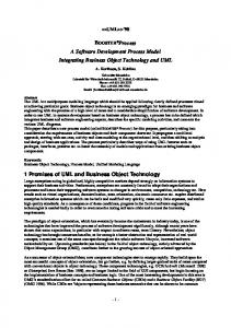
1. Cleanroom software engineering T h e C l e a n r o o m software engineering process combines formal m e t h o d s of software specification, design, and correctness verification with statistical usage testing for quality certification [9]. C l e a n r o o m m a n a g e m e n t is based on d e v e l o p m e n t and certification of a pipeline of user-function increments that execute in the system environment and accumulate t o p - d o w n into the final
product. Fig. 1 depicts the activities p e r f o r m e d and the work products created in the C l e a n r o o m software development process. T h r e e teams perform these activities. The Specification T e a m is responsible for creating the top-level system and software specifications. A system specification defines requirements and behaviors for a solution which integrates some combination of hardware, software, communications, h u m a n behavior, etc. A soft-
0167-9236/96/$15.00 © it996 Elsevier Science B.V. All rights reserved SSDI 0167-9236(95)00022-4
56
C.J. Trammell et al. / Decision Support Systems 17 (1996) 55-71
ware specification defines requirements and behaviors for the software components of the system. Methods for developing formal black box specifications are presented in [7]. Once software specifications are understood, an incremental de-
velopment plan is established. The incremental development plan divides the project into a series of development and certification cycles for building the system. Each Development Team (there may be more
Customerrequirements Specification Function I Usage
Incremental planning
development Functional specification [
Incremental development plan
/
~ Usage specification
:i :ii::iBoxStructure:i: i! I [
UI !1specificationanddesignI
lii
"-Lt CorrectnessverificationI
Usagemodeling Testcasegeneration Test cases
Source eode
i~N: ...... itistl~: ................I /
Failure data
Improvement feedback
;:
Qual, certification
model
Measures of oner~ional p e r f o r ~ c e
Fig.1.TheCleanroomsoftwareengineeringprocess.
C.J. Trammell et al. /Decision Support @stems 17 (1996) 55-71
than one team working in parallel) is responsible for building an inc~:ement. Development teams design and implement the software increments, but do not execute the resulting code. Formal methods, including Box Structure design [14] and function-theoretic correctness verification [11], produce code that is near zero defects prior to first execution. The Certification Team employs statistical usage testing in the system environment to drive the quality of the software to zero defects with high probability. The certification process provides scientific evaluation of product quality expressed in Mean Time To Failure (MTTF) and other statistical measures. In statistical testing, test cases are based on probability distributions that represent eventual product usage, and testing results are used in computation of statistical quality measures based on a certification model. Cleanroom teams are producing software that exhibits extraordinary quality compared to traditional results [6]. For a large project (e.g., over 50 people), these team,; will generally be separate, with some member,; of the specification team continuing in development and certification roles. For a small project (e.g., under 10 people), the specification team may be the same people who later subdivide into development and certification teams. Incremental development has previously been discussed in only a general way in several papers that provide an overview of the Cleanroom method (e.g., [4,6,9]). The objective of this paper is to more fully present the theory and practical application of incre~xlental development in the Cleanroom process. The paper covers the theoretical basis in the mathematical principle of referential transparency, and the practical basis for the application of incremental development. In addition, the paper :identifies the many benefits of incremental dew:lopment that lead to enhanced development productivity and product quality.
2. Key ideas in incremental development Large software systems are organized collections of parts. The parts may be called subsys-
57
tems, components, programs, subprograms, modules, procedures, or, in the language of Cleanroom, boxes. The way a system is decomposed into parts, developed, and integrated has a critical impact on project success. Poor choices can lead to a nightmare of surprises in testing, where all the parts are completed but do not work together as planned. Wise choices can result in few failures in testing, where errors are minor and rework is minimal. This paper concerns the Incremental Development Model of system part definition, development, and integration. The model is integral to the Cleanroom software engineering process, but may be used apart from the Cleanroom process as well. Incremental development is a t o p - d o w n approach to development in which a software system is developed and tested as a succession of cumulative subsets of function. A minimal system is developed in the first increment, and function is added in each successive increment until the system is complete. Each increment contains all previously developed function plus some new function; the system is "grown" in cumulative increments. The key ideas in incremental development are as follows. • Developing the right system requires customer feedback throughout the development process. In incremental development, increments are executed by users in the operational environment to facilitate customer clarification of requirements. Developing the system right requires management control of resources and technical control of complexity. In incremental development, risks to the project are assessed at planned intervals and managed through the incremental development plan. • Product quality requires process control. As an iterative process of complete development cycles (i.e., specification, design, verification, testing), incremental development enables process measurement and control throughout the software development process. Customer control, management control, technical control, and quality control are all afforded by the incremental development approach.
58
C.J. Trammellet al. / Decision Support Systems 17 (1996) 55-71
3. Benefits of incremental development The Cleanroom incremental development process supports rigorous software development in a number of ways. Intellectual Control. Incremental development enables intellectual control over system development through the property of referential transparency. This property (discussed later) is satisfied when subspecifications for functions to be implemented in a later increment are embedded in the procedural logic of the current increment. When referential transparency holds, a system part can be implemented from its subspecification with no need for backtracking; there is no rework of previous increments. This strategy enables correctness verification of each increment within a complete system context. Concurrent Software Engineering. The incremental development schedule enables Cleanroom teams to perform many development activities in parallel. Incremental development allows the specification, development, and certification teams to coordinate increment development and integration in a pipeline process. The use of development resources can be optimized and productivity is maximized. Incremental System Integration. Cleanroom incremental development permits continual integration of referentially transparent user-function increments over the entire development life-cycle. Because the design of each increment is based on a verified subspecification and tested interface in a prior increment, deep design and interface errors are rare. If errors are encountered, time and resources remain for their correction. The system evolves in well-defined increments throughout the development. Testing and certification activities occur early in the development cycle. In traditional development, system parts are often defined according to bottom-up or ad-hoc strategies. Such parts lack referential transparency; they are designed against unconnected subspecifications and untested interfaces that, despite the best of intentions, may be incorrect. As a result, integration problems occur when parts do not work together as anticipated. Because bottom-up parts cannot be executed with-
out resource-intensive scaffolding and driver code, they often undergo simultaneous integration at the eleventh hour of a project, when time and resources are short, and design and interface problems are unwelcome news indeed. Continual Quality Feedback through Statistical Process Control. Incremental development as practiced in Cleanroom provides a basis for statistical process control. Each increment is a complete iteration of the development and testing process. As is typical in statistical process control, measures of performance in each iteration of the process are compared with standards to determine whether or not the process is "in control". Performance is assessed in measures such as errors per thousand lines of code or rate of growth in MTTF. If the process is determined to be "out of control" (i.e., if quality standards are not met), testing ceases and developers return to the design stage. If the process is in control, work on the next increment continues. Feedback produced in each increment is used for project management and process improvement. The team examines all feedback, identifies problems, adjusts project plans if needed, and improves the overall software process as needed. Continual Functional Feedback through Customer Use. Incremental development enables early and continual feedback on the functionality of an evolving system to permit changes, if necessary. Because the increments execute in a system environment and represent subsets of user function, early increments can be exercised by users for feedback on system functionality and usability. Such feedback helps avoid developing the wrong system and builds user acceptance of the eventual product. Change Accommodation. Incremental development allows systematic accommodation of inevitable changes in system requirements and the project environment. At the completion of each increment, the impact of accumulated changes in system requirements can be assessed in terms of current specifications and increment designs. If changes are isolated to future increments, they can often be incorporated within the existing incremental development plan, with possible ad-
c.J. Trammell et al. / Decision Support Systems 17 (1996) 55-71
justments to schedules and resources. If changes affect completed increments, a modified system development can be begun from the top-down, usually with substantial (often total) reuse of code from existing increments, with adjustments to schedules and resources as required. Project M a n a g e m e n t . Project resources can be allocated in a more controlled way through incremental development. The available schedule impacts the number of increments to be developed and thus their size. With a short schedule, a small number of increments will help maintain sufficient intervals between increment deliveries to the certification team to permit an orderly testing process. However, this puts a greater burden on the development teams to design and implement larger, more complex increments. Schedule and complexity tradeoffs can be reflected in the incremental development plan. It is desirable to ,engage the most experienced team m e m b e r s in development of early, high-level increments since major specification and architectural design decMons will heavily impact future increments. Experienced personnel may also be allocated to increments involving particularly difficult and complex functionality.
4. Theoretical foundations of incremental development Incremental development as practiced in the Cleanroom process differs from other life-cycle process models in ks foundation in the mathematical principle of referential transparency. 4.1. M a t h e m a t i c a l foundations
Referential transparency is defined as follows in Denotational Semantics by Joseph Stoy [20]. We use [referential transparency] to refer to the fact of mathematics which says: The only thing that matters about an expression is its value, and any subexpression can be replaced by any other equal in value. Moreover, the value of an expression is, within certain limits, the same wherever it occurs.
59
Referential transparency is the property of arithmetic that allows one to evaluate lengthy arithmetic expressions one piece at a time and still be guaranteed of getting the right answer. For example, in "(6 + 2)* (5 - 3)", because 6 + 2 = 8, the expression in question is equivalent to "8.(5-3)", and because 5 - 3 = 2 , it is also equivalent to "8 * 2", and finally, because 8 * 2 = 16, the original expression is equivalent to 16. Referential transparency guarantees that one can replace (6 + 2) by 8 unconditionally; without worrying, for example, about whether the result will go on to be multiplied by ( 5 - 3), or subtracted from 17, or whatever. Referential transparency is a property of arithmetic, and is proved once and for all in the mathematics of arithmetic. Referential transparency does not need to be checked or rechecked for each individual expression. The concept of referential transparency has been applied in a wide range of areas, e.g., in computer science, linguistics, mathematics, and logic. In general, referential transparency means that the relevant lower-level details of an entity are abstracted rather than omitted in a particular system of higher-level description, so that the higher-level description contains everything needed to understand the entity when placed in a larger context. Examples are given in Table 1. A traditional illustration that English is not referentially transparent is the following, from [18]. Note that while "William Rufus" and "King William I I " refer to the same historical person, the first sentence can be understood while the second sentence makes no sense. 1. William Rufus was so called because of his red beard. 2. King William II was so called because of his red beard. In the C programming language, side-effects are one reason that C expressions are not referentially transparent with respect to their values. For example, the following two C statements both print out 1 plus the current value of x, but they are definitely not interchangeable in any program that subsequently requires the value of x. 1. printf("%d",x + 1); 2. printf("%d", + + x); If the current value of x is 4, then "x + 1" returns
60
c.J. Trammell et al./ Decision Support Systems 17 (1996) 55-71
the value 5 but leaves x unchanged. However, " + + x" returns the value 5 and has the side-effect of setting the new value of x to be 5. The lack of referential transparency in the C programming language does not mean that Cleanroom development cannot be applied using the C programming language. Cleanroom has indeed been applied very successfully with C. The lack of referential transparency described above is a mismatch between entity and description. To restore referential transparency, one can either restrict the entity or enhance the description. Referential transparency can be restored in the first case (i.e., restricting the entity) by using a well-behaved subset of the C language, for example, the D e s i g n / C language [19]. In the second case (i.e., enhancing the description), referential transparency can be restored by using two functions to describe a C expression: one function for the return value, and another function for the new state in terms of the old state. In the Cleanroom method, referential transparency must be established for the desired prog r a m m i n g / d e s i g n language and corresponding functional description. This is done at the outset of a project by a Cleanroom consultant or other person trained in the mathematics of function theory, following the proof technique used for P D L in [11] or using the theory of denotational semantics. Once referential transparency has been established for a particular programming a n d / o r de-
sign language, Cleanroom incremental development and verification techniques are guaranteed to work for any application that is developed in that language. In particular, just as (6 + 2) can be replaced by 8 without regard to the larger context, so can any piece of the application be verified with respect to its functional description without regard to any other piece of the application, and furthermore, need not be reverified if and when other pieces of the application change. Referential transparency is the key to the validity of all of the most basic Cleanroom techniques. In applying Cleanroom to object-oriented development, the functional description of objects and their methods must be enhanced to establish referential transparency. For example, it is not enough to describe the return values of an object method, because calling the method can also affect the internal state of the object itself. Including the update function for the object's internal state would establish referential transparency, but at the cost of exposing internal implementation and destroying information hiding. Fortunately, there is a way to have both referential transparency and information hiding, by using the stimulus history of the object in question. This is the foundation of the Box Structure Method used in Cleanroom development. Once the stimulus history is included in the function description, the effect of one method call on the result of a future method call can be completely captured.
Table 1 Referential transparency in various systems System Entity
Description
Larger c o n t e x t
Arithmetic English Lambda Calculus PDL C programming Language
Value Real-world object Beta-reduced lambda-term Functions Integer-valued Functions
Expressions Sentences LambdaExpressions Programs Programs
a Proved in [11].
(Sub)-expressions Nouns Lambda-terms Program fragments C integer Expressions
Referentially transparent? Yes No Yes Yes a No
C.J. Trammell et al. / Decision Support Systems 17 (1996) 55-71
4.2. Referential transparency in programming The basis for incremental development lies in the view of programs and program parts as rules for mathematical functions [11], that is, as mappings from domains to ranges. This view regards program development as t o p - d o w n refinement of functions (specifications) into control structures and subfunctions (subspecifications), rather than bottom-up aggregation of programming statements into programs. Such refinement may result in object-based or functional decompositions, or a combination of the two. For example, a given function (specification) f could be refined into: [f] = do [fl]; [f2] od [f] = if p then [fl] else [f2] fi If] = while p do [fl] od
sequence alternation iteration
where [fl] and [f2] represent subfunctions (subspecifications) for further refinement. The successive function refi~aements must maintain functional equivalence for correctness verification at each step. For example, in the sequence refinement above, the composition of subfunctions fl and f2 must be equivalent in net effect on data to the original function f. Referential transparency requires that any function (f, fl, or f2 above) completely specify the required net effect of processing at the point it appears in the design, and no further information or reference to other design parts be required for its independent refinement. This crucial property is a key to successful incremental development. Because of referential transparency, the verification of any refinement step can be conducted independently of any other refinement step. This means that the system architecture can be verified in the first increment, before most of the system components have been written, and that the architecture need not be reverified in later increments. Note, however, that the specifications of system components enter into the architecture verification, and in fact provide the precise interface documentation required to guarantee that the system as a whole will perform as required when coding is complete. A simple illustration of function refinement with referential transparency is shown in Fig. 2.
61
The two-step refinement on the right side of the figure maintains function equivalence at each step. First, the initial sequence f is refined into loop initialization code g and subspecification k, where k completely specifies interfaces and the required net effect of processing at that point in the design. Next, subspecification k is refined into an iteration in a second step. These expansion steps are referentially transparent, and represent possible increment definitions. In this case, the first increment would contain the loop initialization code represented by g, with the subspecification k defined and connected in the sequence for verification against f, but stubbed off in the code. A crucial point is that the sequence of code g followed by subspecification k is functionally equivalent to the original specification f. The second increment would refine k into the whiledo iteration, which is functionally equivalent to k. Other design strategies, such the one given on the left side of the figure, would violate referential transparency and forfeit intellectual control of t o p - d o w n design. The difference between these approaches may seem minor in this simple example, but if g and k represent 50 KLOC and 500 KLOC, respectively, with a complex interface between them, referentially transparent increments could mean the difference between success and failure of the project.
4.3. Referential transparency in system design Cleanroom incremental development provides the first opportunity to demonstrate that referential transparency can be applied in a formal way to full-scale system development projects. This is an important insight for the future of systems and software engineering. Consider the following (over) simplified, highlevel architecture for an air traffic control system. Specification "control airspace" (say, 1000 pages of specification text representing an eventual million lines of code) has been refined into a threepart sequence of subspecifications "initialize system" (150 pages), "control all flights" (800 pages), and "finalize system" (50 pages). "Control all flights" has been further refined into a whiledo control structure containing the "control next
62
C.J. Trammell et al. / Decision Support Systems 17 (1996) 55-71
flight" (500 pages) subspecification. Brackets are used for specifications. [control airspace] proc [initialize system] [control all flights] while (flights remain) [control next flight] end [finalize system] corp For referential transparency to hold, the "control airspace" specification must completely define processing requirements and interfaces for its sequence refinement into the three subspecifications, as must the "control all flights" subspecification for its whiledo refinement. The first increment for this system would include top-level
S
components from all three sequence subspecifications, with stubs for later increments. Subsequent increments would extend the functionality of each sequence part in top down-fashion. It may be tempting to define an initial increment for, say, the "control next flight" subspecification, which may be the most interesting part of the problem, but such an approach would break the chain of referentially transparency increments and run substantial risk of integration problems. Of course, the contents of "control next flight" need to be analyzed and understood in order to correctly define the top-level increment, so lots of look-ahead is required; however, the code should go on the machine in a series of top-down, referentially transparent increments. Cleanroom incremental development is wholly consistent with object-oriented development plans
Refinement 1
--~ [
NO
Refinement
2
g k initialization ~--D~[ subcode llspecificationl
S
NO:
YES:
[f] # [while p do h od]
[f] = [g; k]
[while p do h od] * [g; while p do hod]
lg; kl : [g; while p do h od]
Fig. 2. Referential transparency in stepwise refinement.
YES
c.J. Trammell et al. / Decision Support Systems 17 (1996) 55-71
63
[8]. Objects can be specified and developed through refinement steps or reused from an object repository. These objects are then composed into the design and implementation in a t o p down fashion. Referential transparency is maintained by ensuring that all object specifications and interfaces are consistent with the evolving design. If they are not, then either the design must be modified to accommodate the objects or the objects must be customized into the evolving design. Great care must be taken to maintain referential transparency throughout the system design.
quential characteristics (the Spiral model and the Incremental Development model). Other life cycle process models exist, but are peculiar to specific domains or are not prominent in software practice at the present time. Examples of such models, not discussed in this paper, include the Transform model [1], the Ada Process Model, MIL-STD-SDD, and the Next Generation Process Model [2]. The four prominent life cycle process models are characterized below and in Fig. 3. Each model has strengths and weaknesses. Incremental development affords the advantages of the other models without their drawbacks.
5. An incremental development process model
5.1. Waterfall model
Key ideas, benefits, and underlying principles in incremental development have been presented to motivate the more concrete discussion that follows. Incremental development will now be discussed as a process. Incremental development is a "life cycle process model". A life cycle process model specifies the overall sequencing of work in the software life cycle, but is not in and of itself a "well-defined software process". A well-defined software process specifies both (1) the temporal relationship among the major subprocesses in the software life cycle, and (2) the participants, methods, and artifacts in each subprocess in the life cycle. Incremental development and the other models given in this section are examples of (1); they are prominent life cycle process models. Each might be used with many different methods for specification, design, and testing. Cleanroom software engineering is an example of a complete, well-defined software process in which incremental development is the life cycle process model and the associated methods of work are Box Structure specification and design, functional verification, and statistical certification testing. There are at least four prominent life cycle process models in software practice today. One of these models is sequential (the Waterfall model), one is iterative (the Evolutionary model), and the others involve a combination of iterative and se-
The Waterfall model, still in widespread use today, is sometimes described as the best of 1970s software technology. It was a major step forward relative to the code-and-debug process that had prevailed to that time. (The code-and-debug process is, unfortunately, also still in widespread use in mainstream software practice.) The Waterfall model is a sequence of life cycle phases in which the work products of each phase are completed in their entirety before the next phase begins. The results of each phase are verified against the requirements of the previous phase, but with this exception the Waterfall phases generally occur in "one pass". The widely-recognized drawback to the Waterfall model is its underlying assumption that it is possible to completely specify a system at the outset. Numerous blue ribbon panels studying software problems in the US Department of Defense have identified this assumption as a critical cause of project failures. Their collective wisdom on this point was summarized in the 1987 Report of the Defense Science Board Task Force on Military Software. As is true for complex hardware systems, the hardest part of the software task is the setting of the exact requirements... We have no technology and only poor methodologies for establishing such requirements. There are not even good ways in common use for even stating detailed requirements and
64
C.J. Trammell et a l . / Decision Support Systems 17 (1996) 55-71
WaterfallModel SystemFeasibility 1"~ ¢"-1 SoftwareRequirements I"~ K,..I ProductDesign K~-I DetailedDesign K...] Code Integration J-'~ ¢,,..1 Implementation ]"~ K---I Operations/Maintenance] Evolutionary Model Customer
Customer~User Feedback
Requirements---~ ~
Customer
Customer/User Feedback
--~ @
--~ @
Spiral Model
Evaluatealternatives; identify&resolverisks
D~2e2ii;~2bjectives'~
all
Validation Verification
~ ~ D e v e l o p &verify next-levelproduct
Plannextphases
Test
~
.
-
Incremental Development Model
Customer Requirements Top-Level Specification~
Customer~User Feedback
O
Incremental Development Plan Increment ]
Customer/User Feedback
Customer
-Q-@ Increment 2
Increment 3
Complete System
Fig.3.Prominentlifecycleprocessmodels.
C.J. Trammell et al. / Decision Support Systems 17 (1996) 55-71
trade-off priorities. Misjudgments in requirements badly hurt effectiveness, cost, and schedule. Such misjudgments a b o u n d . . . In our view the difficulty is fundamental. We believe that users cannot, with any amount of effort and wisdom, accurately describe the operational requirements for a substantial software system without testing by real operators in an operational environment, and iteration on the specification... [[5], p. 7] Experience with confidently specifying and painfully building mammoths has shown it to be simplest, safesl, and even fastest to develop a complex software system by building a minimal version, putting it into actual use, and then adding function, enhancing speed, reducing size, etc., according to the priorities that emerge from the actual use. Software engineers must recognize that we cannot specify mammoths right the first time...[[5], p. 11] The Defense Science Board Task Force report was extremely influential in the software community. It accelerated the turning of the tide from sequential to iterati~e approaches to software development, in which requirements could be clarified over time. The Incremental Development model preserves the orderly sequence of activities in the Waterfall model, but applies them in a series of cumulative increments.
5.2. Evolutionary development model The evolutionap.¢ development model appeared in the early 1980s [12]. Motivated by the difficulties in the one-pass Waterfall model, its strength is the iterative refinement of requirements through customer feedback on a series of evolving system prototypes. A key problem with the evolutionary model is implied in the fact that this approach is also known as evolutionary prototyping, employing "rapid prototyping" and even "throwaway prototypes". Evolutionar~ prototyping easily degenerates into code-and-debug; "evolution" replaces planning, and expediency prevails so that early user feedback may be obtained. The resulting system may better :reflect user requirements in
65
the short run, but is failure-prone and difficult to maintain in the long run. The incremental development model affords the key benefit of the evolutionary model - iterative clarification of requirements - - but does so according to a top-down, stepwise plan.
5.3. Spiral model The spiral model, introduced by [14] and [1], is based on iterative risk assessment. Boehm's version of the spiral model is given in Fig. '3. In the spiral model, each major activity in a project is planned after a timely evaluation of current risk. The process calls for (1) systematic examination of objectives, constraints, implementation alternatives, and risks, (2) risk resolution activities (e.g., prototyping, simulation, benchmarking) and examination of results, and (3) planning the next phase of the project and gaining commitment from relevant individuals and organizations. Plans arising out of each cycle of the process may be implemented in any way deemed appropriate. While this flexibility seems desirable, it also leaves the practitioner with the ongoing task of process definition. Boehm describes the diverse plans that may follow from risk assessment of project activity subsets. This risk-driven subsetting of the spiral model steps allows the model to accommodate any appropriate mixture of a specification-oriented, prototype-oriented, simulation-oriented, automatic transformation-oriented, or other approach to software development . . . . The appropriate mixed strategy is chosen by considering the relative magnitude of the program risks and the relative effectiveness of the various techniques in resolving the risks . . . . [1, p. 65] The primary advantage of the spiral model is that its range of options accommodates the good features of existing software process models, while its risk-driven approach avoids many of their difficulties. In appropriate situations, the spiral model becomes equivalent to one of the existing process models. In other situations, it provides guidance on the best mix of existing approaches to a given p r o j e c t . . . [1, p. 69]
66
C.J. Trammell et al. / Decision Support Systems 17 (1996) 55-71
The spiral model leaves the actual process model for work as a variable in each iteration. This lack of a sustaining framework for action limits the spiral model's support for project stability. Risk management and process flexibility are the most prominent aspects of the spiral model. Incremental development affords these advantages as well, although risk assessment is not formalized and codified in the design record as it is in the spiral model. This structured approach to risk assessment would be a useful step in developing and revising an incremental development plan.
5.4. Incremental development model Incremental development was proposed by Mills in the early 1970s, but did not gain prominence until the late 1980s when Cleanroom articles and field reports by Mills and associates began to appear. The successive increments in the illustration of incremental development in Fig. 3 represent an unfolding of the "stacked" increments in the Cleanroom process in Fig. 1. In his influential commentary on software practice, No Silver Bullet: Essence and Accidents of Software Engineering, Fred Brooks [3] underscored the profound effects of the incremental development approach. ... Some years ago Harlan Mills proposed that any software system should be grown by incremental development [13]. That is, the system should first be made to run, even if it does nothing useful except call the proper set of dummy subprograms. Then, bit by bit, it should be fleshed out, with the subprograms in turn being developed - into actions or calls to empty stubs in the level below. I have seen most dramatic results since I began urging this technique... Nothing in the past decade has so radically changed my own practice, or its effectiveness. The approach necessitates t o p - d o w n design, for it is a t o p - d o w n growing of the software. It allows easy backtracking. It lends itself to early prototypes.
Each added function and new provision for more complex data or circumstances grows organically out of what is already there. The morale effects are startling. Enthusiasm jumps when there is a running system, even a simple one. Efforts redouble when the first picture from a new graphics software system appears on the screen, even if it is only a rectangle. One always has, at every stage in the process, a working system. I find that teams can grow much more complex entities.., than they can build. [3, p. 18] Incremental development as implemented in the Cleanroom process has the advantages of various other process models-customer involvement, clarification of requirements, risk management, process flexibility-with the additional advantages of quantified product quality and statistical process control.
6. Incremental development: An example A miniature illustration of an application developed under incremental development is given in Fig. 4. (Again, the successive increments in Fig. 4 represent an unfolding of the "stacked" increments in Fig. 1 . ) T h e incremental development plan divides the system into four increments, with reuse of existing components in several increments. Increment 1 includes the user functions of invocation, set-up, and termination. An existing component for managing the user interface is used. Program stubs are used for functions that will be implemented in later increments. T h e stubs are not merely placeholders; they include an interface specification and functional specification so the relationship between implemented functions and stubbed functions is well-defined. Increment 2 consists of Increment 1 plus panel navigation functions. The corresponding stub in Increment 1 is replaced with full function. A preexisting component is used in Increment 2 as well. Increment 3, likewise, consists of Increment 2 plus some new function. The Primary application functions are implemented in Increment 3, re-
C,J. Trammell et al. / Decision Support @stems 17 (1996) 55-71
placing one of the stubs in Increment 2. Three lower level stubs for Secondary application functions exist in Increment 3. Increment 4 is the final increment. The stubs in Increment 3 for Secondary application functions are now imp][emented, and the system is complete. The treatment of stubbed parts of the system is critical to the integrity of the design. Correctness verification of each increment requires that specifications for later increments appear in the procedural logic at their proper points of execution. The completeness of conceptual design in each increment ensures the harmonious integration of new work as development progresses. Fig. 5 shows the incremental development schedule for the preject. After top-level specification, an incremental development plan is established. Both the specification and the incremental development plan are subject to revision after each increment based on development experience, quality measures, and customer feedback.
After each increment is fully specified, designed, and verified, it is submitted for independent certification testing. The measures of quality in certification testing (e.g., MTTF, reliability, errors per KLOC) are gauges of development process control. If measured quality meets established standards, development proceeds. If not, problems are assessed and action is taken to improve the development process. After Increment 1 is submitted for certification testing, development of Increment 2 begins based on its embedded specification in Increment 1. If more than one development team is available, parallel development of Increment 3 may also begin. The Cleanroom incremental development process produces a pipeline of cumulative increments for controlled system development and quality certification. Management decisions on staffing, scheduling, resource allocation, and project planning, tracking, and change accommodation are supported by this incremental process.
Customer
Customer Requirements
67
Customer/User Feedback
Customer/User Feedback
Customer/User Feedback
Top-Level Specification
Complete System
Incremental Development Plan
I " 1 Newly developed Reused 1 Stubbed
Increment 1
Increment 2
Increment 3
Increment 4
Sign on~off Set-up
Sign on~off Set-up Panel navigation
Sign on~off Set-up Panel navigation Prima ryfunctions
Sign on~off Set-up Panel navigation Primaryfunctions Secondary functions
Fig. 4. Incremental development of a small system.
68
C.J. Trammell et al. / Decision Support Systems 17 (1996) 55-71
7. Incremental development strategies
unstable requirements may be planned for later implementation, when questions affecting the requirements have been settled. If the user interface is not well-established, for example, it is an ideal candidate for an early increment. (Some would say that the user interface is invariably the most volatile aspect of the system and should always be implemented in the first increment.) On the other hand, requirements to be settled by concurrent research (e.g., performance benchmarking) might be scheduled for a late increment, after research results are known. Operational Usage Probabilities. A functional usage distribution is developed as part of a toplevel Cleanroom specification. Expected usage probabilities of system functions are established from historical data and best estimates provided by customers. System functions with high expected usage probabilities will receive greatest exposure in the field, and may therefore benefit from the greatest exposure to testing. Since incre-
Many factors can drive increment planning. Customer, application, and technical factors are usually among the most important considerations. Following are common factors in increment planning.
7.1. Customer factors Clarification of Requirements. The common motivation behind iterative development methods is the fact that requirements can rarely be established with certainty at the outset of a project. Under incremental development, customers provide feedback on the evolving system by direct operation of user-executable increments. The relative clarity of requirements may influence an increment plan in two ways. Volatile requirements may be implemented in an early increment, so they can be clarified. Alternatively,
Specification
Incremental Development Planning Increment 1 Design andVerification
I Increment 2 I Design andVerification
I Increment 3 Design andVerification
I Increment 4 Design andVerification
Increment Testing and Certification I
MTTFI
I
MTFI~
T/o'te Fig. 5. An incremental development schedule.
I
MTTF3
I
MTTF4
C.J. Trammell et al./Decision Support Systems 17 (1996) 55-71
ments are cumulative, the functions developed in early increments will be tested several times (i.e., at the conclusion of each increment). System functions expected to receive the greatest operational usage by customers, therefore, are candidates for early increments. Some functions expected to receive low usage may even be regarded as optional, and scheduled for development in the final increment if time permits. Reliability Management. Increasingly, customers are specifyi:ag formal software reliability requirements. [17] described an approach to increment planning based on reliability requirements for subsystems in a high-level design. Given (1) a total system reliability requirement and (2) transitional probabilities between subsystems, the reliability requireme, nt for each subsystem may be calculated. Subsystems with the highest reliability requirements will have the greatest impact on total system reliability, and may be candidates for an early increment. The work in [16] included development of a software tool, the Cleanroom Reliability Manager, to support thi~,; approach.
7.2. Appfication factors System Engineering. "Controlled iteration" is a key engineering principle in hardware development. The minimal machine is built in the first iteration, and is enhanced in subsequent iterations until the complete machine has been built. Incremental development of software is entirely compatible with thi,; standard approach to hardware development. "Smart machines" with embedded software must be developed as a coordinated effort between hardware and software engineers, and incremental development is an ideal framework for this coordination. A machine must be poweredon, for example, before it can be used. The software for system start-up, therefore, would likely be among the functions implemented in the first increment of an embedded software project. Functional Dependencies. In most applications there is some logical allocation of functions to increments based on relationships among functions. In a database application, for example, an
69
add must precede a delete. In a statistical application, data must be entered or retrieved before it can be analyzed. Although program stubs (i.e., null or " T o Be Implemented" responses) may be used in most instances, some initializing functions will require early implementation.
7.3. Technical factors Technical Challenges. Novel or particularly complex work may pose a risk to the schedule or even the viability of a project. If such work is scheduled for an early increment, experience will either lend support to existing plans or point to the need to revise plans. If aspects of the project are not novel or complex in absolute terms, but are indeed novel or complex relative to the experience of the team, an early gauge on feasibility is still desirable. Leveraging Reuse. The Cleanroom process emphasizes economy of effort through (1) reuse of components across projects and (2) identification of opportunities to develop "common services" for use in multiple places within a system. When existing components are identified as potentially reusable, the development team must evaluate the relative effort required to tailor the component for use in the new system versus develop a new component from scratch. If the evaluation is in favor of the component, the team may want to use the component in an early increment in order to validate its expected performance. New common services may be desirable candidates for an early increment as well. Since common services are in multiple places in a system, they have a disproportionate impact on system reliability relative to other, single-instance components. Since objects may be reusable parts, the rationale for object development in an incremental development plan follows the rationale for reusable components in general. Increment planning clearly requires assessment of the specific circumstances in each project. The considerations are both management and technical, and are based on both facts and assumptions. In the next section, incremental de-
70
c.J. Trammell et al. / Decision Support Systems 17 (1996) 55-71
v e l o p m e n t p l a n s f r o m several a c t u a l projects a r e described.
8. Field experience C l e a n r o o m t e a m s in i n d u s t r i a l a n d governm e n t a l o r g a n i z a t i o n s have r e p o r t e d d a t a on close to a million lines of C l e a n r o o m - d e v e l o p e d software. T h e software in t h e s e projects has exhibited a w e i g h t e d a v e r a g e of 2.3 e r r o r s p e r t h o u s a n d lines of code. Q u a l i t y a n d p r o d u c t i v i t y d a t a for the 17 projects c o m p r i s i n g this s a m p l e is given in [6]. I n c r e m e n t a l d e v e l o p m e n t was p r o m i n e n t , for e x a m p l e , in t h e following highly successful projects. • T h e I B M C O B O L S t r u c t u r i n g F a c i l i t y (85 t h o u s a n d lines o f c o d e ) e m p l o y s g r a p h - t h e o retic a l g o r i t h m s to a u t o m a t i c a l l y t r a n s f o r m uns t r u c t u r e d C O B O L p r o g r a m s into functionally e q u i v a l e n t s t r u c t u r e d p r o g r a m s [10]. C O B O L S F was the first C l e a n r o o m p r o d u c t in IBM. • T h e Ericsson OS32 O p e r a t i n g System (350 t h o u s a n d lines of c o d e ) is an o p e r a t i n g system d e v e l o p e d by E l l e m t e l T e l e c o m m u n i c a t i o n s Systems L a b o r a t o r i e s for a n e w family of Ericsson T e l e c o m switching c o m p u t e r s . T h e p r o d u c t t e a m was h o n o r e d by E r i c s s o n as t h e p r o j e c t t h a t h a d c o n t r i b u t e d the most to the c o m p a n y in 1993 [21]. • The IBM AOEXPERT/MVS system (107 t h o u s a n d lines of c o d e ) is a decision s u p p o r t facility t h a t uses artificial intelligence for p r e dicting a n d p r e v e n t i n g c o m p l e x o p e r a t i n g p r o b l e m s in an M V S e n v i r o n m e n t . A O E X PERT/MVS is t h e largest c o m p l e t e d C l e a n r o o m p r o j e c t in I B M [6]. I n c r e m e n t a l d e v e l o p m e n t affords c u s t o m e r f e e d b a c k on the evolving system, i n t e l l e c t u a l control o f t h e t e c h n i c a l work, a n d m a n a g e m e n t control of the s c h e d u l e a n d b u d g e t . U s e r f e e d b a c k on e a c h i n c r e m e n t is a g a u g e on w h e t h e r the right system is b e i n g built, a n d quality m e a s u r e s in e a c h i n c r e m e n t a r e a g a u g e on w h e t h e r the system is b e i n g built right. P r o d u c t quality a n d process control are both supported. Incremental d e v e l o p m e n t has s o u n d m a t h e m a t i c a l a n d statistical f o u n d a t i o n s , b u t has b e e n r e d u c e d to a highly p r a c t i c a l e n g i n e e r i n g process.
References [1] B. Boehm, A Spiral Model of Software Development and Enhancement, Computer, May (1988) 61-72. [2] B. Boehm, Software Process Models: Some New Directions, Journal of the Society for Software Quality, April (1994) 1-9 and May (1994) 1-14. [3] F. Brooks, No Silver Bullet: Essence and Accidents of Software Engineering, Computer, April (1987) 10-19. [4] R. Cobb and H. Mills, Engineering Software Under Statistical Quality Control, IEEE Software, 7(6) November (1990). [5] Department of Defense, Report of the Defense Science Board Task Force on Military Software, September (1987). [6] P. Hausler, R. Linger and C. Trammell, Adopting Cleanroom Software Engineering with a Phased Approach, IBM Systems Journal, 33(1) (1994). [7] A. Hevner and H. Mills, Box Structure Methods for Systems Development with Objects, IBM Systems Journal, 32(2) (1993). [8] A. Hevner and H. Mills, Box-Structured Requirements Determination Methods, Decision Support Systems 13 (1995) 223-239. [9] R. Linger, Cleanroom Process Model, IEEE Software, March (1994). [10] R. Linger and H. Mills, A Case Study in Cleanroom Software Engineering: The IBM COBOL Structuring Facility, Proc. 12th Annual Int. Computer Software and Applications Conf., Los Alamitos, CA (IEEE Computer Society Press, 1988). [11] R. Linger, H. Mills and B. Witt, Structured Programming: Theory and Practice (Addison-Wesley, Reading, MA, 1979). [12] D. McCracken and M. Jackson, Life-Cycle Concept Considered Harmful, ACM Software Engineering Notes, April (1982) 29-32. [13] H. Mills, Top-Down Programming in Large Systems, in: R. Ruskin, Ed., Debugging Techniques in Large Systems (Prentice Hall, Englewood Cliffs, NJ, 1971). [14] H. Mills, R. Linger and A. Hevner, Principles of Information Systems Analysis and Design (Academic Press, NY, 1986). [15] M. Pleszkoch, P. Hausler, A. Hevner, and R. Linger, Function-Theoretic Principles of Program Understanding, Proc. 23rd Annual Hawaii Int. Conf. on System Sciences, January 1990. [16] J. Poore, H. Mills, S. Hopkins, and J. Whittaker, Cleanroom Reliability Manager: A Case Study Using Cleanroom with Box Structures ADL, Software Engineering Technology Report, IBM STARS CDRL 1940, May (1990). [17] J. Poore, H. Mills, and D. Mutchler, Planning and Certifying Software System Reliability, IEEE Software, January (1993). [18] W.V.O. Quine, Word and Object (MIT Press, Cambridge, MA, 1960).
C.J. Trammell et al. / Decision Support Systems 17 (1996) 55-71 [19] S. Rosen, The D e s i g n / C Language for Cleanroom Software Engineering, Proc. 23rd A n n u a l Hawaii Int. Conf. on System Sciences, January (1990). [20] J. Stoy, Denotational Semantics (MIT Press, Cambridge, MA, 1977). [21] L. Tann, OS32 and Cleanroom, Proc. 1st A n n u a l European Industrial Syn~posium on Cleanroom Software Engineering, Q-Labs AB, I D E O N Research Park, S-223 70 Lund, Sweden. J. T r a m m e l l is a faculty m e m b e r in the D e p a r t m e n t of Computer Science at the University of q?ennessee, where she manages the Software Quality Research Laboratory, an applied research and technology transfer program in software engineering. Dr. Trammell has held technical and m a n a g e m e n t positions in s o f t w a r e projects d e v e l o p e d IlW ~ ~ through Oak Ridge National Laboratory, Martin Marietta Energy Systems, and Software Engineering Technology. She received an M.S. in Computer Science in 1991 and a Ph.D. in Psychology in 1981 from the Univer~,;ity of Tennessee. Carmen
M a r k G. P l e s z k o c h is a senior staff m e m b e r with the IBM
Cleanroom Software Technology Center in Bethesda, MD. He holds a Ph.D. in Computer Science.
71
Richard C. Linger is a m e m b e r of the technical staff at the Software Engineering Institute, Carnegie-Mellon University, Pittsburgh, Pennsylvania. He was the founder and director of the IBM Cleanroom Software Technology Center (CSTC), with corporate-wide responsibility for Cleanroom research, development, and technology transfer to IBM laboratories and customers. Mr. Linger managed development of three versions of IBM's first Cleanroom product, the C O B O L Structuring Facility. He has co-authored two software engineering textbooks and has published n u m e r o u s papers on Cleanroom management and technology, software re-engineering, and reverse engineering. He holds a BSEE from Duke University. Alan R. Hevner is an E m i n e n t Scholar and Professor in the Information Systems and Decision Sciences Department in the College of Business Administration at the University of South Florida. He holds the Salomon Brothers/HRCP Chair of Distributed Technology. Dr. Hevner's areas of research interest include distributed database systems, database system performance evaluation, information systems analysis and design, telecommunications, and systems engineering. He has over 60 published research papers on these topics. Dr. Henver received a B.S. in Mathematics (Honors) and a M.S. and Ph.D. in Computer Science from Purdue University.