Proceedings of the 6th JFPS International Symposium on Fluid Power, TSUKUBA 2005 November 7-10, 2005
2A2-2
The Based
Inertia
Simulation
on Hydrostatic
System
Secondary
Control
Jiao Zongxia, Shen Dongkai, Wang Xiaodong and Wang Shaoping No.303 School of Automation Science and Technology Beijing University of Aeronautics and Astronautics, Beijing 100083. P. R. China E-mail:
[email protected]
ABSTRACT
In the study on the braking system, the inertia simulator is necessary, which is generally realized by inertia plate. Its advantage is simple and accurate, whereas the disadvantage is the larger volume and difficult to be adjusted. This paper presents a novel scheme, which is realized by hydrostatic secondary control circuit. The inertia can be increased and decreased by electro-hydraulic servo control through momentum feedback, in which a dual variable servo pump is adopted, with the velocity and torque feedback loops applied. In the beginning, it is set as speed control mode until it reaches the braking speed. Meanwhile, it turns to the sate of inertia simulator, which is the torque control mode, so as to keep the inertia as set value. The function of inertia simulation system based on hydrostatic secondary control is to simulate the momentum, which is realized by momentum feedback control, and it can be calculated through accelerator and desired inertia. The variable pump is driven by constant pressure network, and the variable swashplate is controlled through servo valve. The torque feedback and speed feedback guarantee the control performance requirements. Since there are some problems of nonlinearity, instability, strength friction, etc. a hybrid fuzzy control method are adopted to get higher dynamic control precise and steady characteristics. It is concluded that the scheme and control method is available and validity.
KEYWORDS
Inertia
Simulator;
Hydrostatic
262
Secondary
Control
Copyright (C) 2005 by JFPS,
ISBN 4-931070-06-X
electro-hydraulic servo control through momentum feedback, in which a dual variable servo pump is adopted,
NOMENCLATURE
with the velocity and torque feedback loops applied. In J*:
L:
simulated
angle
KD:
radian
Kp:
system
inertia;
of
the beginning, it is set as speed control mode until it reaches the braking speed. Meanwhile, it turns to the sate
load; Į
of inertia simulator, which is the torque control mode, so
displacement
as to keep the inertia as set value. Secondary control is defined as the regulation of
coefficient;
secondary component in constant pressure network. In the application, the system pressure is not always
pressure;
Jm:
secondary
JL:
inertia
unit
absolutely constant, considering the dynamic characteristics of oil source, pressure storage device and
inertia;
the disturbance of other factors to oil source. Hydrostatic of
load;
KF:
torque
sensor
Bm:
secondary
Gm:
torque
sensor
ψ: Swash
speed;
secondary control system can work in four quadrants, that is, it can work in pump condition as well as motor coefficient;
unit
damping
condition. The energy losing is little and it can be recycled, besides, it is not sensitive to load variation. Domestically or aboard, closed loop speed regulation is
constant;
usually carried out by secondary control, and this is the elastic
ratio;
speed control mode of inertia simulation. Now, some torque servo system based on this theory appears, such as load simulator[1, 2], and its maximal advantage is no extraneous torque, which means that it is not sensitive to
T:torque;
θm:angle
of secondary
load variation. Therefore, during braking test, there is little disturbance to output torque for braking pressure
unit
change. INTRODUCTION SYSTEM
ANALYSIS
By now, Antiskid Brake System (ABS) has been widely used in aeronautics, automobile and other fields. During
The function of inertia simulation system based on
the research and development, it is necessary to implement the braking tests in order to get optimal
hydrostatic secondary control is to simulate the momentum, which is realized by momentum feedback
performance and designation parameters [5]. The inertia simulation device is needed in the test, which is used to simulate the real mass of the aircraft or
control, and it can be calculated through accelerator and
automobile so as to obtain the inertia of tested system[4]. Conventionally, equivalent inertia plate is adopted, which is simple and accurate while the volume is large.
electro-hydraulic torque servo control system, in which the output torque is adjusted by the regulation of the
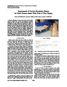
desired inertia. The inertia simulation system is shown in Fig.1. Secondary control inertia simulation a kind of
swashplate angle in constant pressure network. In Fig.1, the inertia plate is used to simulate the road surface, and
So it is difficult to adjust the inertia smoothly in any
driven by secondary component output shaft. The two
direction according to the actual requirement. Using hydrostatic secondary control circuit, the inertia can
be
increased
and
decreased
systems interfere with each other. In order to work on the state of torque and velocity
smoothly by
263
Copyright (c) 2005
by JFPS,
ISBN 4-931070-06-X
feedback,
the
amounted
on the pump
small inertia value
of
torque
inertial
velocity
shaft
braking
simulated.
computer
by given control
In the testing
system,
sensor
with
Output
controls
is of mid
torque
computer the servo
Fig. 1. Diagram
of inertia plate and tyre wheel
simultaneously
in order
to
real
pressure
and
overflow
the
of system must
performance
the torque.
simulate
ABS
sensor is mounted
observation
by A/D,
still to gather
velocities
Pressure
and
valve
law, so as to control the computer
are
a connected
disc, which
angle are fed to control
and the control actuator
and
output
plate against
the
swashplate
sensor
be
condition.
for the sake of the variation
pressure.
regarded
of system,
under
Oil system's
to guarantee
so the fixed
the
quantity
valve system of wide frequency
constant dynamic pump
and
is adopted.
the
of Inertia Simulation
System Based on Secondary
Control
induces the transformations of viscidity and elasticity, CONTROLLER
The inertia simulator complicated are certain
nonlinearity
signal of system inertia torque, the
servo
pressure, and
increasing
inertia
simulation
load pressure a great servo
simulation
delay,
control
system,
and time varying
influencing
of
coupling
presence
valve flux
it has
coefficient
based on secondary
multi-variables
in it. For instance,
and this represents the time varying characteristic of
DESIGNATION
is not a
based
nonlinear
steady state error, but its implementation is very convenient for its simpleness, also it can improve the system robust effectively.
acceleration
causing fluctuation
of
The integral control can be introduced in the controller in
performance; function
order to improve the steady state performance, which can eliminate the steady state error, but the dynamic response
of oil
and the valve core displacement, effect system;
on
forward
is slow, so integration [3] of PID controller and Fuzzy controller constitutes Fuzzy-PID compound controller to
magnification
Furthermore,
time, the oil temperature
with
precise
Fuzzy controller can't study by itself and eliminate the
but there
characteristics
system dynamic
is the
system. Under this circumstance, the mathematical model is difficult to be obtained.
the
improve the steady state performance of Fuzzy controller,
variation
264
Copyright (c) 2005
by JFPS,
ISBN 4-931070-06-X
which
is shown in Fig.2.
In the big error range, small between
error two
range
command it adopts
uses
controls
PID
fuzzy
control.
is automatically
control, The
and in
method
conversion
carried
in
direct
switch,
advance.
switch,
The
straight
conversion
line switch
and
etc.
out by
of Fuzzy PID Controller
In Fig.2f (u1,u2,e) is transitionfunctionof Fuzzy control and PID control. According to current error, to determine the controlled output u , u is a certain integration of u1 and u2 . According to the three f
includes
exponential
Fig.2. Diagram
conversion methods mentioned above,
programmed
set value,
the
system
uses
the
Fuzzy
otherwise,
uses
formula,
ca > 0
the PID
controller
controller
output.
output, In
the
is the threshold.
can be
calculated as follows. (2) (1)
Namely, set value,
Namely,
if absolute
value
of error is less than
otherwise,
a certain
265
if absolute
value of error is larger than a certain
the system uses
the
uses the Fuzzy linear
controller
integration
Copyright (c)
of
2005 by JFPS,
output, the
two
ISBN 4-931070-06-X
controllers
as the
proportions coefficient
of
ultimate each
ke, where,
output.
In the
controller emax>0
is
output,
determined
is conversion
the
Using
the
by
simulations
are
threshold.
initialized
(3) This method exponential The
relation
change
determined
doesn't
speed
need to set threshold.
to integrate
from
along
exponential
the
zero
by a . a is the larger, change
It uses
to infinite. curve
of
change
the braking
While
the inertia
greater
than the one which
acceleration
is the steeper.
mentioned Firstly,
to a velocity
So the simulator
is
method done.
See figure
is used, inertia
suppresses
After
ANALSIS
expected control expected
like a step.
the total inertia
simulator
of about
is
1 second,
directly
is
is not used. by reduce
37Nm
quickly.
4.
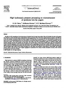
In this case, the actual inertia changes SIMULATION
some plate
the deceleration
to a small constant 3 and figure
inertia
500rpm.
torque to 100Nm simulator
above,
the
sharply
to the
value with a little over shoot, so does the torque performance,
which
one. See figure
the actual torque reaches
5 and figure
the
6.
Brake sharply.
inertia performance
Rotary
Velocity
vuth or vnithout inertia simulator
Fig 5. The actual inertia Fig 3. Velocity
with or without
inertia
simulator
Toroue
acceleration
vnith or Wthout
inertia sirn
control
performance
iator
Fig 6. Torque tracing Fig 4. Acceleration
with or without
inertia simulator
Brake gradually.
266
Copyright (c) 2005 by JFPS,
ISBN 4-931070-06-X
Here,
the
500rpm. adding
inertia After
plate
is initialized
1 second,
change
10Nm per second.
to a velocity
the braking
While the inertia
torque
is not used.
deceleration without
So the simulator
by reduce
acceleration
inertia simulator. rotary velccity
the
to the one
See figure 7 and figure
vuth or without
is
inertia
suppresses
compared
inertia performance
by
simulator
used, the total inertia is greater than the one which simulator
of
8.
inertia simulation
Fig 9 actual inertia
torque control
Fig 7 velocity
with or without
acceleration
performance
inertia simulator
with or vdthout inertia simulator
Fig 10. torque control
performance
CONCLUSION
For the complex structure, nonlinear and mathematical model complexity of inertia simulation system based on Fig 8. acceleration In this expected
case,
with or without
the actual
inertia
secondary control, this paper presents a fuzzy control scheme, its structure is simple and performance is fine.
inertia simulator
changes
sharply
The scheme characteristics are as follows. The torque error and its change are two inputs of fuzzy
to the
value with no over shoot. And the actual torque
traces the expected
control. The swashplate speed is the third input, and its membership function is specially designed to eliminate
one well. See figure 9 and figure 10.
the influence of static friction torque and to minimize the time of zero speed; Using pressure signal to carry out feed-forward compensation, according to the pressure change to adjust the system output gain so as to compensate the torque
267
Copyright (c) 2005 by JFPS,
ISBN 4-931070-06-X
fl uctuation;
Hampton,
Integrating
Fuzzy
organically, regulate
Controller
and
and using exponential the
ultimate
PID
Controller
conversion
method
proportion
of
output
5.
to
for
controllers. show
that
the control
effect
fuzzy
is fine,
the system
exceedance
controller response
necessary steady
is rapid.
to introduce
Fuzzy-PID
error and minish
introduce
pressure
It is also
indicated
control
of
Ki-Chang
performance
system,
Industrial
Symposium
on
Volume
that
Page(s):518
- 523
to
Xu,
Z.,
Taylor,
display
the influence
of pressure fluctuation.
for
Don-Ha
Hwang;
a dynamic
of
aircraft
Electronics,
is small,
6,
of test
the
is
Lee;
Development
of
to eliminate
gain to restrain
Jeon;
Proceedings
dead area, and also necessary
variable
23681-2199.
Kim;
braking
brake
results
and the
Jeong-Woo Yong-Joo
two
The experiment
VA
simulator
with 2002.
anti-skid
2002
IEEE 2,
ISIE
2002.
International
8-11
July
platform
as
2002
vol.2.
D.,
Using
virtual
motion
inertia
Visualization,
2003.
International
Conference
IV
simulation.
2003.
Information
Proceedings. on
a haptic
16-18
Seventh July
2003
Page(s):498-504. 7,
ACKNOWLEDGEMENTS
Zongxia Load
Jiao, Simulator
Control
The author appreciates, the valuable
support
Monika
TORONTO,
Ivantysynova,
Based
Technology, Canada,
on
Xiaodong
Hydrostatic
Sept.
2002,
Wang, Secondary
23rd
ICAS,
pp.346.1•`46.9
provided by the Teaching and Research Award Program for Outstanding Young Teachers in Higher Education Institutions of MOE, P.R.C. and China Aeronautics Science Foundation (No.04E51013) for funding this project. REFERENCES
1,
H.Berg
and M Ivantysynova;
robust
liner
hydraulic
controller
drive,
Department
Design
for
Fluid
mechanical
secondary
power
of Measurement engineer,
and testing
and
controlled
control
and control, the
MS
of a
group,
faculty
of
April
1999
influence
of an
page375-386. 2,
Y M Jen, accumulator
3,
MSc on
the
C B Lee; performance
drive
with control
April
1993 page 173-184.
M. Martin, Design
R. Tburton,
Load
Winter Meeting, W. A. Ragsdale, DYNAMICS Corporation,
of
of the secondary
November
Analysis,
Proceedings
of ASME
1992. LANDING
FOR LASRS++,
Langley
The MS,
Controlled
A GENERIC
NASA
unit,
of Computer
Simulator.
MODEL
a hydrostatic
and G.J. Schoenau,
and Compensation
Hydraulic
4,
and
Research
GEAR Unisys
Center,
268
Copyright (c) 2005 by JFPS,
ISBN 4-931070-06-X