The Overlay Multicast Protocol (OMP): A Proposed Solution to Improving Scalability of Multicasting in MPLS Networks Hind O. Al-Misbahi King Abdulaziz University, Saudi Arabia
[email protected] Abstract With the increasing emergence of group communication applications, and the need for more efficient usage of network resources, multicast techniques and protocols are becoming more vital in networks, and thus need to be given more attention. Multicasting refers to the ability to send information to several receivers at the same time. IP multicast and overlay multicast are two well known approaches that provide multicast services. Several limitations found in IP multicast are addressed in overlay multicast. However, implementation of multicast on MPLS still suffers from IP multicast limitations. This paper proposes a new protocol: the Overlay Multicast Protocol (OMP), in which the overlay approach is applied on MPLS networks to improve the scalability of multicasting. The detailed operations of OMP are explained and a simulation study is presented. The results show the improvement in performance when using OMP.
1. Introduction Due to the increasing popularity of the internet and improved bandwidth, more group communication applications have emerged such as content distribution, teleconferencing, media streaming, distance learning, online gaming, and collaborative workspaces. Multicast service is considered an efficient mechanism to support these kinds of applications. Multicasting refers to the ability to send information to several receivers at the same time using one to many or many to many models. In the early phases of multicast, multicast is implemented in the IP layer and called the IP multicast. IP multicast has not yet been widely adopted due to concerns related to scalability, deployment, and network management.
The 2nd International Conference on Wireless Broadband and Ultra Wideband Communications (AusWireless 2007) 0-7695-2842-2/07 $25.00 © 2007
Arwa Y. Al-Aama King Abdulaziz University, Saudi Arabia
[email protected] To address the issues of IP multicast services, an alternative approach is proposed which is the overlay multicast. In this approach, the multicast functions are implemented at the application layer rather than at the IP layer. This approach is also called Application Level Multicast (ALM). In ALM, the multicast tree is constructed on top of a virtual network which is composed of some nodes. Alongside, MPLS is an advanced forwarding scheme that extends routing with respect to packet forwarding and path controlling. MPLS addresses several network issues such as speed, quality-ofservice (QoS) management, and traffic engineering. Implementing multicast on MPLS also suffers from the scalability problem which limits the concurrent number of groups that can be served and the group sizes. Following is a description of both Multicast & MPLS.
1.1. Multicast IP multicast is the first created model of multicasting [1]. In any IP multicast, there is a need to maintain a forwarding tree for each multicast group. Each tree requires keeping state information at each router at that tree. As the number of groups and the group sizes increase, the amount of state information that must be kept also increases, which in turn leads to the scalability problem. Despite the early invention of the IP multicast service, it is still far from being widely deployed. This is due to several concerns related to scalability, deployment, network management, and the lack of appropriate charging models. The overlay multicast was proposed to address the IP multicast limitations. The overlay is a virtual topology built above the physical network. It is composed of the nodes that are proxies or end hosts that need to participate in the multicast group. The connections between the nodes are unicast paths and may go through several routers. There are several criteria on which overlay multicast can be classified. One of them is the place where the multicast services are implemented. Depending on this criterion, overlay
multicast can be classified into two classes: End System Multicast (ESM) and Proxy Based Multicast (PBM) [2]. In ESM, the multicast functionalities shift from core routers to end systems. While in PBM, the multicast functionalities shift from core routers to proxies which are called Multicast Service Nodes (MSNs). While ESM has more flexibility, it places a substantial burden on the end systems and does not scale well in terms of large group sizes [2]. As this research uses PBM, throughout this paper, any reference to the term overlay multicast refers to PBM.
1.2. MPLS MPLS is a technology in which each MPLS node in the route between the source and the destination forwards data packets using a label attached to the packet. This process is called label switching. The primary goal of MPLS is to switch a packet between routers depending on a small fixed format label rather than performing a lookup on the destination address, which requires more time. Currently, MPLS is gaining more popularity and is being used in more applications. An MPLS capable router is called a Label Switching Router (LSR). The basic operation of an MPLS network is as follows: a label is inserted in a packet header when it enters the network. At each hop, the packet is routed based on the value of the incoming interface and label, and dispatched to an outwards interface with a new label value. The path in which data travels in a network is defined by the transition in label values, as the label is swapped at each LSR. This path is called the Label Switching Path (LSP). Since the mapping between labels is constant at each LSR, the path is determined by the initial label value [3]. At the ingress to an MPLS network, each packet is examined to determine which LSP it should use and, hence, what label to assign to it. This decision is based on factors including the destination address, the quality of service requirements, and the current state of the network. This paper proposes a protocol that applies the overlay multicast model on MPLS networks. It is given the name Overlay Multicast Protocol (OMP). The remainder of this paper is organized as follows: section 2 presents the related work. Section 3 explains the proposed OMP. The methodology used to evaluate OMP performance is presented in section 4. The results of the evaluation are discussed in section 5. And the conclusion is presented in section 6.
2. Related work A framework for IP multicast deployment in an MPLS environment is offered by Ooms et al [4]. It
The 2nd International Conference on Wireless Broadband and Ultra Wideband Communications (AusWireless 2007) 0-7695-2842-2/07 $25.00 © 2007
provides a general overview of the issues arising when MPLS techniques are applied to IP multicast services. An approach described in [5] explains how the label advertisement is piggy-backed on multicast routing messages using Protocol Independent Multicast (PIM). Although this approach advertises the labels without the need for additional control messages beyond those needed to support the multicast routing, it suffers from several disadvantages. It is suitable only with sparse mode protocols such as Protocol Independent Multicast-Sparse Mode (PIM-SM) and Core Based Tree (CBT) which have explicit join messages. The dense mode protocols such as Protocol Independent Multicast-Dense Mode (PIM-DM) have no control messages to allow the piggy-backing. In addition, this approach suffers from all the limitations of the IP multicast mentioned above. With regards to the scalability problem, the aggregated multicast is used in [6], which explains the implementation of aggregation on the VPNs that are built using MPLS. The idea of aggregated multicast is that, instead of constructing a tree for each individual multicast group, multiple multicast groups can share a single aggregated tree to reduce multicast states. With this scheme it is likely that some routers will receive multicast data for which they have no need, thus reducing the optimality of the forwarding trees. Some protocols reduce the forwarding by reducing the number of routers needed to store the forwarding state. For example, in a protocol called MPLS Multicast Tree (MMT) [7], only routers that act as multicast tree branching node routers for a group need to keep a forwarding state for that group. The reduction obtained from this protocol depends on the spread of the members, i.e. if the members are sparse and spread out, the branching points are few and the reduction is high. So, it may be suitable only for limited applications such as video conferencing. Minei et al [8] describe the setup of Point to MultiPoint (P2MP) and MultiPoint-to-MultiPoint (MP2MP) LSPs in MPLS networks. These LSPs are referred to as MultiPoint LSPs (MP LSPs). The solution relies on the Label Distribution Protocol (LDP) without requiring a multicast routing protocol in the network. These MP LSPs are used to apply IP multicast on MPLS networks. Hence, it suffers from all the limitations of IP multicast mentioned above. On the other hand, recently several overlay multicast models were introduced such as ALMI [9], Overcast [10], and OMNI [11]. The overlay multicast has several advantages. First, it does not need support from the network routers which lead to easier deployment than the IP multicast. Second, the state information is kept only in the member proxies rather than the core network routers which improves the
scalability in term of the number of the concurrent groups. In addition, since overlay multicast is an application layer, it permits the implementation of high layer services such as security and access control [9]. The Overlay Multicast Protocol (OMP) proposed in this research is targeted to solve the scalability problem.
3. Overlay Multicast Protocol (OMP) The overlay is a virtual topology constructed above a physical network using a set of devices called proxies. These proxies are connected to the physical network through access links. The connections between the proxies are unicast paths. The clients or the receivers subscribe to the closest proxies. The following subsections illustrate the operations of the proposed OMP.
3.1 Group identification Each multicast group is identified by a group ID which consists of owner proxy IP and group number. The first part is the IP address of the proxy where the group was initialized. The second part is a local unique number at the owner proxy.
3.2 Session initialization When a source node wants to distribute data to a set of receivers, it must obtain a group ID that identifies the new session from its proxy. Then it announces the group ID to the receivers through a method such as email or a URL site.
3.3 Joining the group When a proxy has one or more clients that request to join a multicast group, it sends a join message towards the owner proxy. The owner proxy collects the join requests that have reached before the beginning of the session, then, computes the Minimum Spanning Tree (MST), and distributes the routing information to the member proxies using response messages. The response message informs each member about its parent and children in the tree. If a new proxy wants to join the group during the session, it sends a join message towards the owner proxy. The owner proxy connects that new member to an existing proxy in the current MST and sends the routing information to that member. MST is computed periodically to reflect the frequent modification of the members.
The 2nd International Conference on Wireless Broadband and Ultra Wideband Communications (AusWireless 2007) 0-7695-2842-2/07 $25.00 © 2007
When the member receives the response message, it sends a connect message to its parent to establish a connection between them. The parent returns a connect-ack message to the child. The computation of MST needs the owner proxy to know the delay between the member proxies. This knowledge is obtained from the members themselves. Each member measures the delay between its node and all the other proxies using ping messages. Then the members send the measurements towards the owner using a probe message. This process must be repeated periodically to reflect the change of the paths. With respect to the first computation of MST, each member must add the delay measurements to the join message when it joins the group. The connections between the proxies are bidirectional as the next paragraph will explain. The owner proxy is the administrator of the group which means that it is responsible for the tree building and maintenance but doesn’t mean that it is the unique source of the data. Any member proxy can send the multicast data because MST is a shared tree. MST is similar to the MP2MP LSP [8] in the building such that when the leaf members receive the response messages, they establish both a downstream and an upstream LSP; propagate the request toward their parents which are transit nodes. Transit nodes (which are non leaf members) support the setup by propagating the downstream and upstream LSP setup toward the root and installing the necessary MPLS forwarding state. The root node installs a forwarding state to map traffic into the MP2MP LSP.
3.4 Leaving the group When a proxy wants to leave the group, it sends a leave message towards the owner proxy. This happens when the proxy has no clients that want to receive the multicast data. But if this member proxy doesn’t represent a leaf node in the tree, it must continue the forwarding of the multicast data to its neighbor proxies until it stops receiving the response messages from the owner proxy for a specified time.
3.5 Tree modification Due to the frequent joining and leaving during the session, the tree may have some nodes that are connected but are not members of the group. The tree may also have some nodes that are connected to a nonoptimal position in the tree because they were added to the tree after completion of the MST computation. To address this problem MST is computed periodically.
The member who leaves the group must continue to forward data packets to its neighbors until it sees that there are no response messages reaching to it. At that point, the member will realize that the owner assigned a new parent to its children. The waiting period must be longer than the response-interval taking into account the time needed by the leave and the response messages to travel on the network. A short responseinterval increases the tree optimality because it reflects the dynamic changes immediately but it increases the control overhead. So there is a tradeoff between the tree optimality and the control overhead. It is obvious that the owner proxy can fail during the session. As in [9] multiple back-up nodes of the owner can be used to make the service fault tolerant. These back-up nodes must contain all the required information to deliver the service to the receivers such that they can be in place of the original owner proxy if it fails. The addresses of the back-up nodes must be known to the members. The response messages, which are sent periodically from the owner, allow the members to detect the owner failure. It is clear that there is much work to be done by the owner proxy for each session. If a proxy is an owner of a large number of sessions, it is preferable to transfer the new requests of establishing multicast sessions to another proxy which has a light load. This can improve the performance and balance the load especially when there is a high load on the network. The tree may be also modified due to a member failure. If that member is not a leaf node, the connectivity of the tree will be affected. To detect the member failure, the messages connect and connect-ack must be sent periodically. When a child member doesn’t receive the connect-ack message for a specific time taking into account the time needed by the messages to travel, it detects that the parent failed. In this case it must rejoin the group by sending a new join message towards the owner proxy. If a parent proxy detects that its child failed, it doesn’t do any thing but stop forwarding the data to that child. In case of a member failure, some of the packets are lost in some member proxies. When a member detects a data loss, and at the same time detects a neighbor failure, it requests the lost data from the sender proxy. In this case the failing member is the proxy who delivers the data from the sender. I.e. the member who detects the data loss but doesn’t detect a neighbor failure doesn’t request the lost data. This reduces the requests that reach to the sender. After receiving the lost data, the member who sent the request sends the lost data to its neighbors other than the failing one.
4. OMP performance evaluation This section provides a performance evaluation of OMP through simulation. The performance of OMP is compared to PIM-SM which uses the piggy backing methodology to assign and distribute labels found in [5]. The sending periods of PIM-SM control messages are taken in accordance to the PIM-SM specification [12]. The sending periods of OMP control messages were 5 minutes for ping, probe, and response messages and 60 seconds for connect messages. The simulation was conducted in a seventy one nodes’ topology abstracted from some real network routes. The traceroute utility was used to record routes between 18 sites, and then the topology was constructed from the recorded routes. All the links in the topology were bidirectional links with a 1 second delay and a cost equal to one. The simulation ran the protocols on 1000 concurrent groups. Four different group sizes were used as follows: 250 groups with 10 members, 250 groups with 30 members, 250 groups with 50 members, and 250 groups with 70 members. The owner and the members were selected randomly. The following metrics were used in the simulation. Average table size of each node: The table size is the number of forwarding states in a node’s table. First the total number of the forwarding states is computed. Then, it is divided by the number of the topology nodes to obtain the average value. Total control messages for each protocol: This metric presents the total number of the control messages needed to build the multicast trees. Average delay of the receiver: The delay of sending data to a receiver is measured in terms of the number of physical hops. While each link has a 1 second delay, the number of hops represents the delay in seconds. To compute this metric, the delay of each receiver in the tree is calculated. Next, the summation of all the receivers’ delay of the tree is calculated. And finally, the average delay of the receiver of that tree is calculated. Then the average is computed in term of all the groups. Average cost of each tree: The tree cost is the number of links of that tree. First the cost of each tree is computed. Then the average is computed by dividing the cost by the number of trees. Average stress of the tree links: Link stress is the number of identical copies of a packet carried by that link. Using IP multicast, every link in the network has a stress of exactly one and this is the ideal value. Using OMP, there is a chance to carry more than one copy of a packet by a link. The average stress is computed as
∑
si
i∈ L
L
The 2nd International Conference on Wireless Broadband and Ultra Wideband Communications (AusWireless 2007) 0-7695-2842-2/07 $25.00 © 2007
where L represents all the links of a tree, | L|
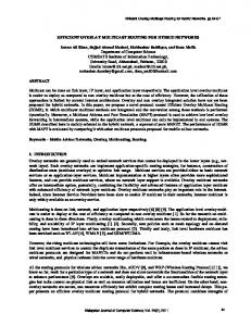
Figures 1-5 compare the results of the metrics for both the PIM-SM and OMP protocols. It is obvious that OMP provides better performance in term of the average table size, the total control messages, the average delay of receiver, and the average tree cost. However, results show that OMP provides more stress than PIM-SM. The difference between the average table size of PIM-SM and OMP is due to that OMP stores the routing data only in the member proxies rather than all the routers in the path between the source and the receivers. The total control messages metric computes only the backbone messages and exclude the end hosts membership messages which means that control messages of OMP are determined mainly by the number of member proxies. The routers in trees of PIM-SM are more than the proxies in trees of OMP, which results in the difference in the tree maintenance overhead in the two protocols. The ping messages are not affected by the number of the concurrent groups. Also the periods used for ping, probe, and response messages help to improve the control overhead of OMP. The persistence of the internet routes have been measured by Paxson [13] who found that 91% of routes are persistent for 10 minutes time scales and nearly 100% with less time scales. This research used 5 minutes time scales. With regards to the delay, there is a small difference between the two protocols. PIM-SM builds shared trees with shortest paths while OMP builds MSTs. Although it is expected that this would lead to less delays in PIM-SM, it actually doesn’t. This is because in PIM-SM the shortest paths must go through RP which is the core of the tree, causing more delays in PIM-SM than OMP. As shown in figure 3, there is no regular relation between the average delay of receiver and the group size because the delay is averaged with respect to each receiver and the members are selected at random.
The 2nd International Conference on Wireless Broadband and Ultra Wideband Communications (AusWireless 2007) 0-7695-2842-2/07 $25.00 © 2007
average number of entries
250 200 PIM-SM
150
OMP
100 50 0 10
30
50
70
group size
Figure 1. Average table size 3000000 total control messages
5. Results and discussion
300
2500000 2000000 PIM-SM
1500000
OMP
1000000 500000 0 10
30
50
70
group size
Figure 2. Total control messages 14 average delay of receiver
represents the number of the tree links, si represents the stress of link i, where i is the link number. All the metrics take into account only the relation between the proxies in case of OMP and between the designated routers in case of PIM-SM. So, the relation with the clients is excluded.
12 10 8
PIM-SM
6
OMP
4 2 0 10
30
50
70
group size
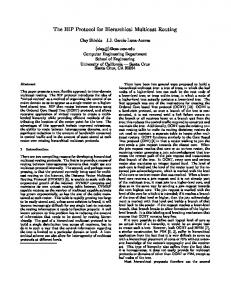
Figure 3. Average delay of receiver The tree type built for each protocol affects the average tree cost. The MST, used in OMP, focuses on building trees of less costly links. With respect to stress, PIM-SM, as any IP multicast protocol, achieves the ideal value which is one packet. OMP, on the other hand, provides stress that reaches 1.8 packets in average. In these terms, IP multicast protocols are more efficient in term of the resource utilization in the network. This is, however, a problem that is common among all overlay protocols and is not specific to OMP. The problem is caused by the fact that when a proxy follows a unicast path to forward packets to other proxies, it may receive and send data over the same link, causing duplicate packets on links close to the proxy.
80
[3] E. Rosen, A. Viswanathan, and R. Callon, “Multiprotocol Label Switching Architecture”, IETF RFC3031, Jan. 2001.
average cost of tree
70 60 50
PIM-SM
40
OMP
30 20 10
[4] D. Ooms, B. Sales, W. Livens, A. Acharya, F. Griffoul, and F. Ansari, “Overview of IP Multicast in a Multi-Protocol Label Switching (MPLS) Environment”, IETF RFC3353, Aug. 2002.
0 10
30
50
70
[5] D. Farinacci, Y. Rekhter, and E. Rosen, “Using PIM to distribute MPLS labels for multicast routes”, IETF Internet draft, Nov. 2000, "work in progress".
group size
average stress
Figure 4. Average cost of tree
[6] E. Rosen, and R. Aggarwal, “Multicast in MPLS/BGP IP VPNs”, IETF Internet Draft, May 2005, "work in progress".
2 1.8 1.6 1.4 1.2 1 0.8 0.6 0.4 0.2 0
PIM-SM OMP
10
30
50
70
group size
Figure 5. Average stress of link
6. Conclusion This paper proposed OMP which applies the overlay service in MPLS networks. OMP provides a solution for multi-sender multicast communication. The general operations of OMP were explained. Through simulation results, the performance of OMP was compared to PIM-SM which applies piggy backing to distribute the labels. OMP achieves significant improvement of scalability because it stores the state information only in the member proxies. The simulation results indicate that OMP achieves reasonable performance in terms of control overhead, tree cost, and delay. In addition, the increase of the stress value in OMP is relatively low and reasonably acceptable especially when focusing on the achieved benefits and the several limitations it solves that are found in IP multicasting such as the difficulty of deployment and network management.
7. References [1] K. C. Almeroth, “The evolution of multicast: from the MBone to interdomain multicast to Internet2 deployment”, IEEE Network, vol.14, no.1, pp.10-20, Jan./Feb. 2000. [2] Y. Zhu, W. Shu, and M. Wu, “Approaches to Establishing Multicast Overlays”, in proceedings of IEEE International Conference on Services Computing, vol.2, pp.268-269, Jul. 2005.
The 2nd International Conference on Wireless Broadband and Ultra Wideband Communications (AusWireless 2007) 0-7695-2842-2/07 $25.00 © 2007
[7] A. Boudani, and B. Cousin, “A new approach to construct multicast trees in mpls networks”, In Seventh IEEE Symposium on Computers and Communications, pp.913-919, Jul. 2002. [8] I. Minei, K. Kompella, I. Wijnands, and B. Thomas, “Label Distribution Protocol Extensions for Point-toMultipoint and Multipoint-to-Multipoint Label Switched Paths”, IETF Internet draft, Jun. 2006, "work in progress". [9] D. Pendarakis, S. Shi, D. Verma, and M. Waldvogel, “ALMI: An Application Level Multicast Infrastructure”, in proceedings of USENIX USITS, pp.49-60, March 2001. [10] J. Jannotti, D. Gifford, K Johnson, M. Kaashoek and J. O'Toole Jr., "Overcast: Reliable Multicasting with an Overlay Network", in proceedings of USENIX OSDI, pp197212, Oct. 2000. [11] S. Banerjee, C. Kommareddy, K. Kar, B. Bhattacharjee, and S. Khuller, “Construction of an efficient overlay multicast infrastructure for real-time applications”, in Proceedings of IEEE INFOCOM, vol.2, pp.1521-1531, Mar./Apr. 2003. [12] B. Fenner, M. Handley, H. Holbrook, and I. Kouvelas, “Protocol Independent Multicast - Sparse Mode (PIM-SM): Protocol Specification (Revised)”, IETF Internet Draft, Oct. 2004 "work in progress". [13] V. Paxson, “End-to-End Routing Behavior in the Internet”, in ACM SIGCOMM, vol.26, no.4, pp.25-38, Oct. 1996.