FR5REP091
Proceedings of PAC09, Vancouver, BC, Canada
THE PRIMARY EXPERIMENT OF MULTIPACTOR ELECTRON GUN BASED ACCELERATOR M. Zhong, S. X. Zheng#, C. X. Tang, Tsinghua University, Beijing 100084, P. R. China Abstract The Multipactor Electron Gun (MEG) can produce high current self-bunching electron beams. In this paper, the primary experimental results of an S-band MEG based accelerator are presented. The accelerator was modified from a 6MeV standing wave accelerator to integrate the MEG, which has an adjusting structure to control both the cathode-grid distance and frequency tuner. The designed output energy is 5MeV and average current is 100mA. The experiment included low power microwave parameter measurement and high power beam test. In the microwave parameter measurement, the relationship between tuner position and E-field distribution was investigated. Platinum was used as the secondary electron emitters of the MEG. The multipacting process was observed and an average current of 40mA was collected by an aluminium target.
optimized by using numerical simulation with the design output energy of 5MeV and an average current of 100mA.
DESIGN & COLD TEST The mechanical structure was designed with ability of replacing secondary electron emitters. Platinum is used as the secondary electron emitters of the MEG. The distance between electrodes and the resonant frequency of the MEG can be adjusted separately by step motors. The structure of the MEG accelerator is shown in Figure 1.
INTRODUCTION Multipactor electron gun is a new kind of cold cathode microwave electron gun. It has the advantages of short duration, high current electron beams, simple structure and long lifetime. Therefore it is very suitable for small industrial and medical accelerator or high power microwave generation. F. M. Mako designed Micro-Pulse Electron Gun (MPG) in 1993 [1]. The MPG (S-band) reached a high macro-pulse current density of 10A/cm2 [2, 3]. The Accelerator Lab of Tsinghua University has been doing research work on MEG since 1999. The research work includes Theoretical Analysis, simulation [4], design, manufacture, cold test and high power experiments and multipactor material et.al [5]. With CVD diamond cathode, a macro-pulse current density of 1.2 A / cm2 was reached [6]. A 6MeV standing wave accelerator was modified to integrate the MEG, and the microwave parameters were tested [8]. This paper presents the primary experimental results of this S-band MEG based accelerator.
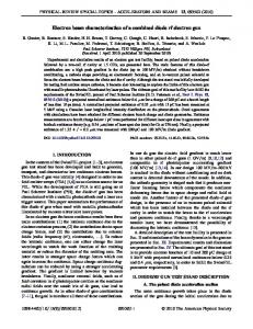
Figure 1: Structure of the MPG accelerator. The size of the single electron emitter is Φ10 mm in diameter and 0.15mm in thickness, two emitters are mounted face to face. The cathode-grid distance is 2.5mm. The accelerating tube consists of 2-cell buncher and 5-cell accelerating section, excited by a 2MW magnetron. The field distribution is measured by a HP8720B network analyzer and the result is shown in Figure 2.
PRINCIPLES MEG is a resonator in front of the accelerator cavity chains, and parts of the microwave power feed into MPG through coupling holes. The electron beam is produced, amplified and then bunched simultaneously in the cathode-grid gap. When the current in the cavity reaches a steady level by space charge and beam loading effect, the outgoing electron beams will be the saturation emission current. Finally the emission current comes into the accelerating cavity and is accelerated. We choose a standing wave accelerating tube works on S-band, 2.998GHz. The parameters of the accelerator tube were
Figure 2: Normalized field distribution. The electrical field of the MEG cavity is affected by the position of the tuner, the field distribution of the first three cavities was measured with different tuner positions. The cathode-grid distance is 2.5mm and tuner depth changes from 0.5mm to 3.5mm. The electrical field
___________________________________________
#
[email protected]
Low and Medium Energy Accelerators and Rings 4990
A08 - Linear Accelerators
Proceedings of PAC09, Vancouver, BC, Canada
FR5REP091
amplitude becomes lower with the tuner becomes deeper, as shown in figure 3.
Figure 5: MEG tube on experiment bench.
Figure 3: Normalized field distribution of the first three cavities. On the symmetrical point of tuner, there is a microwave probe to measure the electric field intensity. During the microwave parameter test, the possibility of monitoring MEG cavity field amplitude via microwave probe is verified. The signal intensity is good enough by electric coupling. Figure 4 shows the frequency dependence of S21 with different tuner depth. The signal attenuation drops from -33dB to -36dB while the tuner depth grows from 0.5mm to 3.5mm, corresponding to figure 3.
Because of the usage of flange, vacuum exhaust cannot be preceded. So when the microwave power first feed in, strike fire occurred frequently. The plasma produced by strike fire was accelerated and received by the aluminium target. Figure 6 shows the target signal (ch1) and the pulse current signal from magnetron (ch2) when no strike fire happens.
Figure 6: Signal without strike fire. Figure 7 shows the above signals when strike fire happened. The signal was very incoherent and had very high amplitude which was about 20V. Figure 4: Frequency dependence of S21.
HOT TEST RESULT The high power experiment was performed on a S-band microwave system. The magnetron is an EEV MG5349 which provides microwave between 2992MHz and 3001MHz. A power meter was used to monitor the RF signal form the microwave probe in the MEG cavity. The current was collected by an aluminium target which was placed at the end of the accelerator tube. A 100Ω resistance was used for sampling. The tube was placed on the experiment bench, as shown in figure 5.
Figure 7: Signal with strike fire. After the strike fire went down, the cathode-grid distance was adjusted to 2mm. The tuner was also adjusted to keep the resonator frequency. The power signal in MEG cavity was observed through power meter, as shown in the figure 8.
Low and Medium Energy Accelerators and Rings A08 - Linear Accelerators
4991
FR5REP091
Proceedings of PAC09, Vancouver, BC, Canada
Platinum MEG experiment was 30mA, so the capture rate is about 15%.
CONCLUSIONS An S-band accelerator based on MEG has been manufactured and primary tested in the Accelerator Lab of Tsinghua University. Pt and was used as SE emitters. The microwave parameters were measured and the feasibility of tuner and microwave probe was investigated. During high power experiments a maximum current of 5mA was observed. Figure 8: Power signal in MEG cavity. The power envelop became decreased in the later part, which indicates beam loading in the MEG cavity. This means that multipactor was occurred. Meanwhile the signal of the aluminium target was shown in figure 9.
Figure 9: Multipactor signal. The channel M was after subtracting background signal to show a clean multipactor current, which is about 500mV or 5mA. The maximum current we got in the
REFERENCES [1] F. M. Mako, W. Peter, “A high-current micro-pulse electron gun”, PAC’93, Washington D.C., May 1993, p. 2702 (1993). [2] S. K. Guharay, L. K. Len, F. Mako, “X-band highcurrent micro-pulse electron gun for accelerators”, IVEC 2002, California, p. 174 (2002). [3] S. K. Guharay, L. K. Len, F. Mako, “High-current micro-pulse electron guns and accelerator applications”, PAC’01, Chicago, p. 2084 (2001). [4] C. X. Tang, Z. F. Jiang, K. Tian, High Energy Phys. and Nuclear Phys. 27 (2003) 546. [5] J. Y. Zhai, C. X. Tang, S. X. Zheng, High Energy Phys. and Nuclear Phys. 30 (2006) 147. [6] J. Y. Zhai, C. X. Tang, S. X. Zheng, “Multipactor Electron Gun with CVD Diamond Cathodes”, EPAC’06, Edinburgh, p. 3203 (2006). [7] Y. Z. Lin, “Low Energy Electron Linac Principle”, Tsinghua Univ. 1999. [8] M. Zhong, S. X. Zheng, C. X. Tang, “The design of a 5MeV accelerator based on multipactor electron gun”, EPAC’08, Genoa, July 2008, p. 1520(2008).
Low and Medium Energy Accelerators and Rings 4992
A08 - Linear Accelerators