Proceedings of the 2nd International Symposium on Adaptive Motion of Animals and Machines, Kyoto, March.4-8, 2003
SaA-I-2
The RoboCoq Project : Modelling and Design of a Bird-like Robot Equipped with Stabilized Vision V. Hugel1, A. Abourachid2, H. Gioanni3, L. Mederreg1, M. Maurice3 O. Stasse1,4, P. Bonnin1, P. Blazevic1 1
2
Laboratoire de Robotique de Versailles (LRV), UVSQ hugel,mederreg,blazevic,
[email protected] Muséum National d’Histoire Naturelle (MNHN). UMR 8570 CNRS-MNHN-P6,
[email protected] 3 Laboratoire de Neurobiologie des Réseaux Sensori-moteurs (LNRS) UMR 7060 CNRS-P5-P7,
[email protected] 4
Laboratoire de Traitement et Transport de l’Information (L2TI), Paris XIII, stasse @l2ti.univ-paris13.fr Keywords : bird-like biped locomotion, avian kinematic model, stabilized vision, head-bobbing.
Abstract The RoboCoq project aims at designing a prototype of autonomous biped based on the avian model. According to biological studies conducted at National Museum of Natural History in Paris (MNHN) the locomotion system of birds appears to be more efficient than the human model in terms of stability, stride length and mobility. Moreover due to its morphology the foot of a bird seems to be more polyvalent and suitable for support and crossing of pebbly terrain. The objective of this project is to design a robot capable of exploring cluttered environments and returning visual feed-back to the operator at a remote location. For this purpose the robot should also be equipped with a stabilized vision system that will be inspired by the headbobbing reflex used by birds to stabilize images on their retinas. The design of the robot will rely on experimental kinematic and dynamic data obtained from the animal. The information collected will serve as a basis for modeling and simulating the locomotion system of the bird, and will help reproduce the head-bobbing reflex on the robot. This project has just started and involves the participation of 3 teams of biologists and roboticians issued from the MNHN, the LNRS, and the LRV. This paper presents some features of the avian model compared with the human model, gives a first simplified kinematic model of the locomotion system and describes the experimental protocol to be conducted to get all the biological data from the animal.
1. Introduction Biped robots encounter a lot of interest in several countries. Oddly they are all inspired by the human model except some prototypes built in the MIT and others built to imitate the locomotion system of biped dinosaurs. In Japan, researchers and industrial firm engineers are working on building complete prototypes capable of walking and seeing like Man. A robot that looks like and acts like a human should appear more friendly to the people around who may interact with it and trust it. In France researchers from INRIA designed and built a human biped robot called BIP to study
problems related to walking gait generation and control [1]. The machine was designed to move indoors autonomously, walk on slightly inclined surfaces, and climb up human-scale stairs. Each leg of BIP can move round three axes of rotation with respect to the pelvis. There are also 3 rotary degrees of freedom between the trunk and the pelvis. A leg is equipped with 6 active joint mechanisms, three rotary joints at the hip, one at the knee and two at the ankle. All the joints of BIP are active and researchers are planning to introduce compliance at the foot level. In the United States scientists from MIT [2] have focused on proving the importance of using compliance in a walking system. Active joints like electric servos are responsible for a certain inertia and friction that impose the dynamics of the robot. The impedance of such actuators is very high with respect to the leg structure. Passive mechanisms allow for reducing joint impedance and approximating torque source at the joints. The use of passive mechanisms at foot level provides better interaction with the ground by using less rigid trajectories than those produced by means of electric actuators. MIT researchers have favored the natural dynamics of members issued by muscles rather than the dynamics of actuators. For this purpose they designed series elastic actuators [2], where a spring is placed in series with the output of the actuator, after the gear reduction. These mechanisms feature low impedance and reduced friction. Among the biped robots they designed the Spring Flamingo robot looks like a bird [2]. It is a planar robot with three rotary joints per leg, one at the hip, one at the knee and the last at the ankle. Joints are actuated through cables. Motors are located on the upper part of the robot. The robot’s leg structure features only 3 degrees of freedom (d.o.f.) whereas the leg of a bird has 7 d.o.f.. However the objective of the research in MIT was to demonstrate the benefit of using such compliant mechanisms in
SaA-I-2
biped robots, and to develop adapted walking algorithms. In the project described in this paper, the RoboCoq robot must be capable of operating in 3D space, and not constrained to move in 2D space. Moreover it should be autonomous in terms of power and be able to chose by itself the right gait to use to cross the irregularities it may encounter along its path. If possible, Robocoq should be able to cross human-scale environments. Compared to the BIP robot, RoboCoq will be inspired by the avian model, which should confer it better performances. Studies conducted in MIT are very useful and give some hints for designing a compliant bird-like leg structure.
2. The Avian Model Due to the anatomical requirements for the flight, birds represent the most homogenous class among the vertebrates from a morphological point of view. At the same time, birds present an extensive adaptive radiation and live in every kind of environment: aquatic, terrestrial, arboreal … [3][4][5]. Birds use two locomotive apparatuses. The first one comprises the wing and the tail, and is used mainly for the flight. The second one comprises the legs, used mainly for terrestrial locomotion. It is not the purpose of this project to design a complete birdlike robot but to focus on the leg structure. The animal chosen to conduct biological studies is the quail. The quails used have been selected for their adaptability [6][7]. They are well suited for walking. Birds are the only animals to share a strict bipedy with humans. Several characteristics suggest that the avian model is more stable than the human
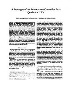
model [8]. As a matter of fact the centre of gravity is located under the hip joint (fig. 1) whereas among humans it is located above in the lower part of the trunk. Among birds the trunk is suspended by the hip joints. The hind limb of the birds is characterized by the presence of three segments (fig. 1). The first one that joins the hip and the knee joints is nearly horizontal and allows for bringing back the leg below the gravity centre. It may also plays the role of a stabilizer of the trunk. The two other segments are the most mobile parts. The "foot" of the birds is primitively formed by four fingers only, with three toes pointing forward and one pointing backward. It is therefore much simpler than the human foot. The flexibility of the 4 fingers and the large base they form allow high stability, even on irregular ground. If we compare the stride length with respect to the leg height in the table below, we have a ratio of 1 for the human model compared to a ratio up to 2.2 for the quail. features
Human
Bird (quail)
Stride length
100 cm
20 cm
Hip height
100 cm
9 cm
Ratio (stride length over hip height)
1
2.2
The bird model appears to be better than the human model in terms of stability and stride length.
3. Designing the Bird Locomotion System Model 3.1 Biological data acquisition
hip
gravity center knee heel fingers
Fig.1. Rooster skeleton showing leg joints Modified from De Juana (1992) [9]
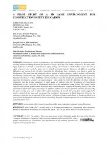
The first phase of the project will consist of analysing the dynamic and kinematics features of walking quails. The force exchanged between the bird and the ground as well as the movements of the centre of mass during locomotion will be studied using force plates. Figure 2 shows the three piezoelectric sensors that will be used to design the experimental force plate. These piezoelectric sensors are manufactured by KISTLER. The kinematics data, especially the displacement of skeletal segments, will be collected by X-ray analysis coupled with high rate digital camera acquisition. This study will allow us to measure the amplitude and the phase shift in movements of each leg, to determine the mechanisms responsible for the animal balance, and to define the strategy adopted by birds when walking on an irregular ground. It will also give us information for
SaA-I-2
dimensioning the segments and actuators for the prototype. In a second phase we will choose the
Fig.2. KISTLER piezoelectric sensors for the force plate
kinematics and mechanical characteristics of the powered segments of the robot. Then we will test them by simulation. The various loads and physical parameters related to the mechanics of the segments will be used to calculate the dimensioning of the joints, actuators, masses and inertia. The geometrical placement (position and orientation) of the various elements such as segments, joints, actuators and proprio- and extero-ceptive sensors will be adapted to the robotic structure, which will be different from the bird structure. 3.2 Simplified kinematics structure When looking at the leg model of a bird, one can see that it owns one additional segment with respect to the human model. In fact, both models feature a hip joint and a knee joint. Whereas in the human model the heel belongs to the foot, in the avian model a “heel joint” is linked to the foot by a third segment. This feature should confer a better mobility to a robot based on the avian model.
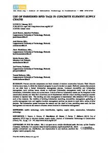
Fig. 3. RoboCoq simplified kinematics scheme
First biological observations permit to define a simplified kinematics model that is depicted in figure 3. The model displays 7 degrees of freedom for each leg, including 3 active rotations at the hip level, 1 active rotation at the knee level, 1 active rotation at the heel and 2 active rotations at the foot joint. The rotation axes of the knee and the heel, as well as one rotation axis of the hip and of the foot articulations will be parallel in the frontal plane. The second articulations of the foot and hip will have their axis parallel with the direction of displacement. The third articulation of the hip will allow rotation around the vertical axis. In contrast to the human model or the BIP robot, the movements of the trunk cannot be decoupled with respect to the legs. In fact when the bird walks its body follows an almost straight horizontal line. This is different for the human model where the centre of gravity oscillates periodically along the vertical. The study of the avian foot and its robotic reproduction appears to be difficult. Even if it seems less complex than the human foot, the role of the toes in the walking balance keeping is determining. It is necessary to use elastic passive mechanisms and tactile sensors to imitate the toe when holding and leaving ground. Moreover a special blocking device of the toes should be incorporated in order for the robot to stand firm on the foot when touching ground. Therefore the locomotion system of RoboCoq should be equipped with 14 active rotary joints, and with 3 or 4 passive mechanisms for each foot.
4. The Vision Stabilization System 4.1 The head-bobbing reflex Species that feature foveated vision such as primates and some birds need to orient their gaze in order to fixate an interesting stimulus. During locomotion, vertebrates stabilize their gaze (eye + head) with respect to the environment to avoid retinal slip, and consequently a blurring vision. This stabilization is carried out by reflexes triggered either by vestibular (angular acceleration of the head) or visual (retinal slip) stimulation [10][11][12]. They result in a compensatory rotation of the eyes with respect to the head and/or of the head with respect to the body. Moreover, birds display a peculiar visual reflex called head-bobbing. During the walk birds quickly project their head straightforward and then keep it fixed with respect to the environment whereas their body moves. This motion is performed periodically. Just after projecting its head forward,
SaA-I-2
the bird stabilizes its gaze and is therefore able to perceive its environment precisely. In order to better understand the synchronization mechanisms between the walk and the head-bobbing reflex, the Robocoq project intends to use a variable speed treadmill synchronized with visual stimuli. This original system will allow to observe behavioral adaptation, by focusing on the synchronization of legs and/or head movements that are involved during locomotive and gaze stabilizing responses in pigeons. Results obtained with the animal will allow to reproduce the bird's headbobbing reflex on the robot. Coupling the head reflex and the locomotive movements should ensure a stabilized vision during the robot displacements.
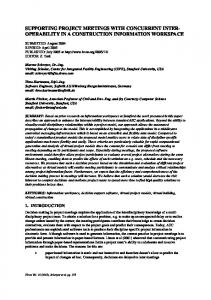
Fig. 4. The micro camera to be used for the PA10 robot
To implement such a reflex on the avian robot, we plan to design an articulated neck whose extremity will bear a vision system composed of two steerable cameras. Figure 4 shows the camera that will be used. The neck comprises two segments that can rotate with respect to each other (see figure 3). There is a rotoid joint between the head and the neck, and one rotary joint between the neck and the body. The articulated neck features 5 additional d.o.f.. It will allow to position the head during body motion. The stabilizing phase of the head-bobbing reflex will be triggered and maintained by a servo-control mechanism elaborated from an analysis of the optical flow. A compensatory reflex of the eyes relative to the head rotation (reproducing the vestibulo-ocular reflex) will additionally be installed. The rotation of the cameras will be triggered by a gyrometer. 4.2 The benefit of reproducing the head-bobbing reflex in Robotics The articulated neck will be used to reproduce the head-bobbing reflex that makes up for visual movement. To our knowledge every robotic vision system built for mobile robot is rigidly fixed to the body structure. Even so, a stereoscopic head includes a neck that allows to track a target, but none of them can make up for the motion induced by the whole body (also called ego-motion in active vision).
This is not a problem for a wheeled mobile base. As a matter of fact, because most of the motion is smooth, ego-motion can be discarded using kinematics models projected into the image reference frame. Ego-motion is crucial as it allows to discriminate visual information given by the environment from visual information induced by the current robot action. It is used for smooth-pursuit based on optical flow, and for gaze fixation during exploration. For legged robots, the motion involved by highly dynamic movements, or the motion resulting from crossing rocky terrain makes ego-motion computation much more difficult. The use of an articulated neck together with the head-bobbing reflex may simplify the problem. Indeed the neck will try to make up for the motion perceived by the optical flow in order to minimize the ego-motion effect on the visual system. Consequently the robot computational power will not be needed to compute the inverse kinematics from all the proprioceptive information. A more direct application for RoboCoq is to send a flow of images to a remote human operator. It is well known that people looking at images returned by legged robots in motion tend to become ill quickly. We hope that RoboCoq will be able to provide more comfortable visual information. 4.3 A first experiment on visual stabilization In order to validate our concept, a Mitsubishi PA-10 arm robot will be used together with a CMOS micro camera, a 3-axis accelerometer and a 3-axis gyrometer. The PA-10 arm has 7 degrees of freedom, which is enough to simulate the neck (upper part of the robot) and the body motion (lower part). The micro camera (11 g) and a radio emitter for sending images will be placed at the top of the arm. The experiments will be conducted as follows: • • • • •
the visual stimuli (visual environment) will be moved backward on two lateral screens. the cameras will measure the optical flow motion. the upper part of the arm simulating the neck will make up for the computed optical flow to stabilize the camera. when the arm's part simulating the neck motion will near the range limit, a forward projection will be generated. the arm's lower part could be moved to simulate additional displacements of the body during the walk.
SaA-I-2
Figure 5 shows the different degrees of freedom available on this robot, which makes it suitable for our purpose. This set-up will be used to validate neurophysiological and control models during the design of the robot's neck.
Figure 5. The Mitsubishi PA10 robot
5. Conclusion This project aims to design an original autonomous bipedal robot, suitable for displacements on irregular ground. The stabilized vision will permit a remote control of the robot using on board vision allowing minimal discomfort for the operator.
6. Acknowledgments The RoboCoq project is supported by the French ROBEA program (Robotics and Artificial Entities) set up by CNRS, the French National Scientific Research Committee. The three partners, MNHN, LNRS and LRV would like to thank the organizers for granting the project the amount of 90 K€ over 2 years. We also thank J.M. Faure, from INRA, who kindly gives us quails. The RoboCoq team is also grateful to KISTLER for helping the project by making special prices on piezoelectric sensors.
7. References [1] B. Espiau P. Sardain, 2000. The Biped Robot BIP2000, IEEE Int. Conf. on Robotics and Automation, San Francisco, April 2000. [2] J E. Pratt , 2000. Exploiting Inherent Robustness and Natural Dynamics in the Control of Bipedal Walking Robots, PhD Thesis, MASSACHUSETTS INSTITUTE OF TECHNOLOGY, June 2000.
[3] A. Abourachid and S. Renous, 2000. Bipedal locomotion in ratites (Paleognatiform) : examples of cursorial birds. Ibis, 142 : 538-549. [4] A. Abourachid, F.Lambert, A Msimanga and P.Y. Gagnier. In press. Adaptations for walking on floating vegetation : the case of the jacana. [5] A. Abourachid, 2001. Comparison of kinematic parameters of terrestrial locomotion in cursorial (Ratites) swimming (ducks) and striding birds (quail and guinea fowl.) J. Comp. Biol. Physiol. A 131 : 113-119 . [6] A.D.Mills and J.-M. Faure, 1991. Divergent selection for duration of tonic immobility and social reinstatement behavior in Japanese Quail (Coturnix coturnix japanica) chicks. J. Comp. Psychol.. 105: 25-38. [7] J.-M. Faure and A.D. Mills. 1998. Improving the adaptability of animal by selection. In Genetics and the behavior of domestic animals. T. Grandin edt. Academic Press. London. : 235-264. [8] Gatesy, S.M. and Biewener, A.A. 1991. Bipedal locomotion: effects of speed, size and limb posture in birds and humans, J. Zool., Lond. 224 : 127-147. [9] E. de Juana, 1992, Class AVES (birds) in Handbook of the birds of the world. J. Del Hoyo, A. Elliot and J. Sargatal eds Lynx Edicions Barcelona. Volume 1. [10] H. Gioanni, 1988a. Stabilizing gaze reflexes in the Pigeon (Columbia livia). I. Horizontal and vertical optokinetic eye (OKN) and head (OCR) reflexes. Exp. Brain Res. 69 : 567-582. [11] H. Gioanni, 1988b. Stabilizing gaze reflexes in the Pigeon (Columbia livia). II. Vestibulo-ocular (VOR) and vestibulo-collic (closed-loop VCR) reflexes. Exp. Brain Res. 69 : 583-593. [12] H. Gioanni, and A. Sansonetti, 1999. Characteristics of slow and fast phases of the optocollic reflex (OCR) in head free pigeons (Columba livia): Influence of flight behaviour. European J. Neurosci. 11:155-166.