The Soft Error Problem: An Architectural Perspective 1
Shubhendu S. Mukherjee,1 Joel Emer,2 and Steven K. Reinhardt1,3 FACT Group Intel Corporation 77 Reed Road, Hudson MA 01749
[email protected]
3
2 VSSAD
Intel Corporation 77 Reed Road, Hudson MA 01749
[email protected]
Advanced Computer Architecture Lab EECS Department, University of Michigan 1301 Beal Avenue, Ann Arbor, MI 48109
[email protected]
1. Introduction
2.1. SDC & DUE
Radiation-induced soft errors have emerged as a key challenge in computer system design. Exponentially increasing transistor counts will drive per-chip fault rates correspondingly higher unless new technologies are employed. If our industry is to continue to provide customers with the level of reliability they expect, microprocessor architects must address this challenge directly. This effort has two parts. First, architects must understand the impact of soft errors on their designs. Second, they must select judiciously from among available techniques to reduce this impact in order to meet their reliability targets with minimum overhead.
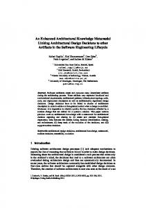
Figure 1 illustrates the possible outcomes of a single-bit fault. Outcomes labeled 1-3 indicate non-error conditions. The most insidious form of error is silent data corruption (SDC) (outcome 4), where a fault induces the system to generate erroneous outputs. To avoid SDC, designers often employ basic error detection mechanisms, such as parity. With the ability to detect a fault but not correct it, we avoid generating incorrect outputs, but cannot recover when an error occurs. In other words, simple error detection does not reduce the overall error rate, but does provide fail-stop behavior and thereby avoids any data corruption. We call errors in this category detected unrecoverable errors (DUE). Currently, the industry specifies soft error rates in terms of SDC and DUE numbers. We further subdivide DUE events according to whether the detected fault would have affected the final outcome of the execution. We call benign detected faults false DUE events (outcome 5 of Figure 1) and others true DUE events (outcome 6). A conservative system that signals all detected faults as processor failures will unnecessarily raise the DUE rate by failing on false DUE events. Alternatively, if the processor can identify false DUE events (e.g., the fault corrupted only the result of a wrong-path instruction), then it can suppress the error signal. DUE events can also be divided into process-kill and systemkill categories (not shown in Figure 1). In some cases, such as a parity error on an architectural register, an operating system (OS) can isolate the error to a specific process or set of processes. The OS can then kill the affected process or processes but leave the rest of the system running. We call such a DUE event process-kill
The research community can play a significant role in both of these areas. On the first front, we must develop better conceptual frameworks, analysis techniques, and software tools to advance both intuitive understanding and quantitative measurement of how soft errors affect system behavior. On the second front, we must expand and characterize the space of soft error avoidance, detection, and recovery techniques so that solutions are available to reach various reliability targets within realistic performance, power, area, and complexity constraints. To provide a foundation for these efforts, this paper gives a broad overview of the soft error problem from an architectural perspective. We start with basic definitions (Section 2) followed by a description of techniques to compute the soft error rate (Section 3). Then, we summarize techniques used to reduce the soft error rate (Section 4). Section 5 describes problems we face with double-bit errors. Finally, in Section 6 we outline future directions for architecture research in soft errors. Table 1 provides a summary of acronyms used in this paper.
2. Background and Metrics Transient faults arise from energetic particles—such as neutrons from cosmic rays and alpha particles from packaging material—generating electron-hole pairs as they pass through a semiconductor device. Transistor source and diffusion nodes can collect these charges. A sufficient amount of accumulated charge may invert the state of a logic device—such as an SRAM cell, a latch, or a gate—thereby introducing a logical fault into the circuit’s operation. Because this type of fault does not reflect a permanent failure, it is termed soft or transient. Current trends suggest that soft errors from particle strikes will be an increasing burden for microprocessor designers in future. The raw error rate per device (e.g., latch, SRAM cell) in a bulk CMOS process is projected to remain roughly constant or decrease slightly for the next several technology generations [6][7]. Thus, unless we add more extensive error protection mechanisms or use a more robust technology (such as SOI), a processor’s error rate will grow in direct proportion to the number of devices we add to a processor in each succeeding generation. In contrast, however, by slowing the reduction of cell capacitance and supply voltage, DRAM vendors have managed to reduce the soft error rate per bit with every technology generation [2].
faulty bit is read? no
1
yes
benign fault; no error
bit has error protection? detection & correction
fault corrected; 2 no error
affects program outcome? no
3
benign fault; no error
yes
4
SDC
detection only
no
affects program outcome? no
5 false DUE
yes
6 true DUE
Figure 1. Classification of the possible outcomes of a faulty bit in a microprocessor. SDC = silent data corruption. DUE = detected unrecoverable error.
Proceedings of the 11th Int’l Symposium on High-Performance Computer Architecture (HPCA-11 2005) 1530-0897/05 $20.00 © 2005 IEEE
Term
Explanation
next section discusses the device error rate, while the following section describes the SDC and DUE AVFs.
FIT
Failure in Time, 1 FIT = 1 failure in a billion hours
3.1. Device Error Rate
MTTF
Mean Time to Failure
SER
Soft Error Rate
The device error rate (measured in FIT) is the product of the particle flux and the underlying circuit error rate determined by the technology and implementation. To the first order, the error rate is directly proportional to the particle flux rate. Alpha particles typically arise from contamination in the packaging material, solder, etc. Special shielding materials can dramatically reduce the impact of alpha particles on semiconductor devices. Terrestrial neutrons arise when cosmic rays coming from deep space interact with the earth’s atmosphere. Several feet of concrete are required for neutron shielding, which is impractical for most applications. Neutron flux increases with altitude. For example, at 1.5km in Denver, Colorado (USA) the flux is approximately 5x higher than at sea level, while in an airplane flying at 10,000 km it is about 100x higher. The circuit error rate for RAM cells, latches, and dynamic circuits is the product of the raw circuit error rate and a timing vulnerability factor (TVF). The raw circuit error rate indicates the likelihood of a specific cell experiencing a bit flip. The minimum charge required to flip a cell is called Qcrit. Qcrit depends on the cell’s capacitance and voltage. The amount of charge a circuit can collect, depends on its area and its collection efficiency, which is a measure of the amount of charge generated from a particle strike. For dynamic circuits, we must factor in the error masking effects from a strike on any of the pull-down nodes. The raw error rate of a cell can be computed by simulating current pulses of all magnitude on all nodes of a cell at different points of time. Unfortunately, this can be very compute intensive. Hence, for full-chip simulations, usually we use approximate models or Monte Carlo simulation techniques. We derate the circuit’s raw error rate by its TVF. The TVF is the fraction of each cycle during which a bit flip in a cell will be captured. RAM cells are typically always vulnerable; thus their TVF is 100%. In contrast, latches typically hold data for 50% of the time, when they are vulnerable, and are driven 50% of the time, when they are not vulnerable. Consequently, the TVF of a latch is roughly 50%. Recently, Seifert and Tam [13] have shown that the TVF of a latch in a high-frequency design is likely to be much less than 50% because a strike late in the hold phase may not have enough time to propagate to the next latch in a pipeline. Unlike RAMs, latches, and dynamic nodes, static logic requires special consideration. A strike on a static logic device, such as a NAND gate, causes an error only if a forward state element, such as a latch, captures the effect of the bit flip. A strike on a static logic device may not propagate to the forward latch because of three masking effects [14]: electrical masking (glitch attenuates before arriving at the latch), latch-window masking (glitch does not arrive within the setup and hold time of the forward latch), and logical masking (glitch is on a “don’t care” term of the logic feeding the latch). Hence, the error rate of a static logic gate can be expressed as the product of the raw error rate and a propagation vulnerability factor (PVF). The PVF is the fraction of static logic faults that cause a bit flip in the forward latch. The FIT/bit of a cell typically ranges between 0.001 - 0.010 [11][17]. At present the contribution of static logic to the overall error rate is assumed to be small, but Shivakumar, et al. [14] predict that contribution of static logic will soon equal that of latches.
Table 1: Glossary of Acronyms
SDC
Silent Data Corruption
DUE
Detected Unrecoverable Error
ACE
Architecturally Correct Execution
un-ACE
Unnecessary for Architecturally Correct Execution
AVF
Architectural Vulnerability Factor
TVF
Timing Vulnerability Factor
PVF
Propagation Vulnerability Factor
DUE. The remaining DUE events fall into the system-kill DUE category, as the only recourse is to bring down the entire system.
2.2. FIT & MTTF Both SDC and DUE rates are typically expressed in FIT (Failure(s) in Time). One FIT signifies one error in a billion (109) hours. FIT rates are additive, so we can compute the SDC or DUE FIT rate of a chip or system by summing the SDC or DUE FIT rates of all its components. The sum of SDC and DUE FIT is usually referred to as the soft error rate (SER) of a chip. The additive property of FIT makes it convenient for calculations, but Mean Time to Failure (MTTF) is often more intuitive. MTTF is inversely related to FIT. A FIT rate of 1000 is equivalent to MTTF of 114 years (= 109 / (1000 X 24 X 365)). Both MTTF and FIT are defined relative to the domain over which the corresponding FIT contribution is computed. For example, the FIT rate of a complete computer system can be quite low even though individual system components have a higher FIT rate, e.g., as in a triple-modular redundant system (see Section 4.3.2). Vendors typically set soft-error-rate budgets for their chips or systems based on target market requirements. For example, IBM targets 114 SDC FIT (1000 yr MTTF), 4,566 system-kill DUE FIT (25 yr MTTF), and 11,415 process-kill DUE FIT (10 yr MTTF) for its Power4 systems [3]. The absolute rates and the relative importance of SDC and DUE depend on the target market. A system with extensive error detection mechanisms will have a low SDC FIT rate but a higher DUE FIT rate, while only machines with comprehensive fault recovery schemes will have low rates for both SDC and DUE FIT.
3. Computing SDC & DUE FIT A key question for a design team is whether their chip or system meets its SDC and DUE FIT budgets. The soft error rate of a chip or its components can be measured via accelerated (and somewhat expensive) neutron beam tests in cyclotrons or alpha particle tests using radioactive Thorium foils. Of course, these techniques require a functioning chip, at which point it is expensive and possibly too late to correct any reliability problems. In this paper, we focus on modeling and computing—rather than measuring—the soft error rate of a chip. As discussed above, the SDC and DUE FIT rates of a chip can be computed by summing the contributions of each component. Each component FIT rate is the product of two factors: a raw device error rate, which indicates the rate of transient-faultinduced state changes, and the device’s architectural vulnerability factor (AVF), which is the probability that a state change in the device leads to an architecturally visible SDC or DUE error. The
Proceedings of the 11th Int’l Symposium on High-Performance Computer Architecture (HPCA-11 2005) 1530-0897/05 $20.00 © 2005 IEEE
Assuming a FIT/bit of 0.001, TVF of 50%, a target system size of four CPUs, an SDC FIT budget of 114 FIT (Section 2.2), and the entire SDC budget is allocated to unprotected latches, then a processor can have up to 57,000 (= 114 FIT / (0.001 FIT/bit x 0.5 TVF x 4 CPUs) unprotected latches in the design. Unfortunately, today’s billion-transistor processors can have 10-1000x more latches as well as other unprotected bits in the machine. Clearly, meeting the SDC (and DUE) FIT budget is a challenging issue. In the following subsections, we describe the SDC and DUE AVFs and how they are used to calculate a processor’s SDC and DUE FIT rates. In Section 4, we examine current techniques to reduce a processor’s FIT rates.
3.2. SDC AVF A device’s SDC AVF expresses the probability that a bit flip in that device results in an error in a program’s output. Given our single-bit fault model, a device protected by a single-bit error detection or correction mechanism cannot cause an SDC event, so its SDC AVF—and its contribution to the overall SDC rate—is zero. Bit flips in multiple bits could cause SDC events; we discuss this issue separately in Section 5. The SDC AVF of unprotected devices varies according to their function and utilization. For example, an upset in a branch predictor bit will not result in a user-visible error; therefore, its SDC AVF is zero. Conversely, an upset in the program counter will most likely result in executing the wrong instructions; therefore, the SDC AVF of the program counter is practically 100%. Computing SDC AVFs for other structures, such as the instruction queue, is more involved. For example, an instruction queue entry containing information pertaining to a wrong-path instruction will have a zero AVF. At some other point in time, the same physical entry may contain a vital correct-path instruction, resulting in a high AVF. Mukherjee, et al. [10] introduced the concept of architecturally correct execution (ACE) to compute the SDC AVF of such structures. Architecturally correct execution encompasses any execution that generates results consistent with the correct operation of the system as observed by a user. Individual instructions may generate incorrect results without violating ACE if those results are never observed outside the system (e.g., they are dead values). Recent work has shown that even executing the wrong instructions need not violate ACE [18]. A bit is called an ACE bit when it contains information that, if changed, will affect the final outcome of the program. It is called an un-ACE (un-necessary for ACE) bit otherwise. The SDC AVF of a storage cell is the fraction of cycles it contains an ACE bit. If a program executes for 10 million cycles and a storage cell contains an ACE bit for 1 million of those cycles (and, hence, an un-ACE bit for the other 9 million cycles), then the SDC AVF of that cell is 10%. The SDC AVF of a structure is the average of the SDC AVFs of all cells in that structure. Mukherjee, et. al. [10] reported an SDC AVF of 29% for the unprotected instruction queue of an Itanium2-like processor. Although we describe the concept of SDC AVF at the bit level, it applies to static logic as well. The SDC AVF of static logic is the same as the SDC AVF of the forward latch it feeds. The AVF computation for static logic is a little more involved if the logic chain feeds multiple forward latches.
DUE AVFs. The DUE AVF is the sum of the true DUE and false DUE AVFs (see Section 2.1). Protecting a structure with an error detection mechanism (but no recovery scheme) actually increases the overall error contribution from the structure. A fault that would have been an SDC event now becomes a true DUE event, so the true DUE rate equals the old SDC rate. However, some faults that would have been benign because the program outcome was unaffected will now be detected, generating false DUE events. Furthermore, error detection schemes generally add extra bits which raise the false DUE rate of the structure as well. Thus, the total DUE AVF of the protected structure will be at least as large as, and probably greater than, the SDC AVF of the unprotected version. A fault in an error detection bit, such as a parity bit, would cause a false DUE event.
3.4. Computing SDC and DUE AVFs There are three known ways to compute AVFs of different processor structures: statistical fault injection, analytical models, and performance models (simulators).
3.4.1. Statistical Fault Injection Statistical fault injection (SFI) is a time-tested technique for measuring vulnerability factors. SFI introduces bit flips—randomized in both time and space—into a model of the structure being studied, such as an RTL (register transfer language) or performance model. We then run forward and compare the architectural state of the model with the state of an error-free model. After some number of simulation cycles, if the comparison does not result in a mismatch, the error is either latent in the processor or has been masked. The latter can be determined via a thorough comparison of microarchitectural state of the two models [19]. The AVF of the structure being studied is estimated as the fraction of mismatches observed divided by the total number of bit flips introduced. SFI is a very powerful technique and has the advantage that it does not require a priori understanding of the processor architecture being studied. Unfortunately, SFI makes sense only in a very detailed model, such as RTL, which models all processor state bits. RTL models are usually much slower than performance models and can realistically be run for only tens of thousands of simulated cycles per injected error. Hence, computing the AVF of every processor structure would require an enormous amount of compute power to cover a sufficiently large number of injected errors. Finally, a mismatch between the models with and without errors may not necessarily mean that there is an error because architectural state may actually contain un-ACE bits, such as dynamically dead register values.
3.4.2. Analytical Model using Little’s Law In selected cases when bits flow unmodified and without duplication through a structure, we can use Little’s Law to compute its AVF. Little’s Law can be stated as N = B × L, where N = average number of bits in the structure, B = average bandwidth per cycle into the structure, and L = average latency of an individual bit through the structure. Applying this to ACE bits, we get the average number of ACE bits in a structure as the product of the average bandwidth of ACE bits into the structure (Bace) and the average residence cycles of an ACE bit in the structure (Lace). Thus, we can express the AVF of a structure as:
3.3. DUE AVF The DUE AVF is the probability that a strike will result in a detected unrecoverable error. Only components that have error detection but not error correction (e.g., parity) will have non-zero
B ace × L ace --------------------------------------------------------------number of bits in structure
For example, for the instruction queue, Bace is the IPC (instructions per cycle) times the number of ACE bits per instruction. Lace is the residence cycles of ACE bits in the instruction
Proceedings of the 11th Int’l Symposium on High-Performance Computer Architecture (HPCA-11 2005) 1530-0897/05 $20.00 © 2005 IEEE
queue. This technique is useful in the early stages of a design when neither a performance model nor RTL may be available. We can also obtain estimates of Bace and Lace from a performance model.
3.4.3. ACE Analysis in a Performance Model Both the SDC and DUE AVFs of various processor structures can be computed using a performance model. The basic idea is to identify which objects flowing through the machine are ACE and which are un-ACE. The fraction of time a bit contains ACE state is, by definition, the AVF of the bit. We refer to this process as lifetime analysis. The key challenge of lifetime analysis with a performance model is to identify the un-ACE fraction of a bit’s lifetime. (To provide a conservative upper bound on the AVF, we assume a bit is ACE unless it can be shown to be un-ACE.) Examples of instructions that give rise to un-ACE state are dynamically dead, wrongpath, and falsely predicated instructions. Lifetime analysis requires an in-depth understanding of the architecture and microarchitecture. Otherwise, we may end up with an AVF number that is artificially too high. Unlike SFI, however, ACE analysis in a performance model is much faster because AVFs of a large number of processor structures can be computed in one experiment. Also, a performance model can be realistically be run for tens of millions of cycles. Thus it can potentially provide greater accuracy than SFI.
4. Techniques to Reduce the Soft Error Rate A variety of techniques exist to keep the SDC and DUE rate of a chip within the its FIT budget. Overall, the solution space can be divided into process, circuit, and architectural solutions.
4.1. Process Technology Solutions A key process technology that can help reduce SER is siliconon-insulator (SOI). Unlike bulk CMOS, SOI devices collect less charge from an alpha or neutron particle strike because the silicon layer is much thinner. IBM reports a 5x reduction in SER of SRAM devices from partially-depleted SOI technology [5]. However, it is unclear whether we get similar reductions in SER from SOI latches and logic devices. Fully-depleted SOI, in which the silicon layer almost disappears, has the potential to offer further reduction in SER. Nevertheless, volume manufacturing of fullydepleted SOI chips is still a challenge.
4.2. Circuit Solutions Since SOI does not solve the entire SER problem and may not be available in all companies, circuit technologies and architectural solutions can provide alternate mechanisms to reduce the SER. Such circuit techniques typically involve tuning the device parameters and creating radiation-hardened (or rad-hard) cells. Examples of such tuning could involve increasing the capacitance and/or supply voltage of a device. Both of these raise the Qcrit, thereby lowering the SER. Rad-hard cells may also contain redundant state that can recover from a particle strike [4]. Unfortunately, rad-hard cells come with significant area and power penalty, so these cells must be used judiciously.
4.3. Architectural Solutions Architectural solutions may be more effective than circuitlevel solutions for two reasons. First, the definition of what constitutes an error typically lies in the architecture (e.g., a strike on a branch predictor does not result in an error in a microprocessor). Second, typical solutions, such as parity or ECC, often can be amortized over a large number of bits. For example, SECDED (single error correct double error detect) ECC has the overhead of 8 bits per 64 bits of data (i.e., 13%), whereas rad-hard cells can have an area penalty of 30-100% depending on the aggressiveness
of the SER reduction technique used. However, in places where ECC incurs a performance penalty (e.g., extra cycle(s) to verify the ECC code), rad-hard cells may be a better solution. Architectural solutions to reduce SDC and DUE can be classified broadly into two categories: micro and macro solutions.
4.3.1. Micro Solutions Examples of micro solutions are parity, SECDED ECC, and the π bit [20]. Parity is typically an XOR of all the data bits and can detect any single-bit error. A bit protected with parity typically has an SDC AVF of zero, but non-zero DUE AVF. Even the DUE AVF for parity-protected structures may be reduced to zero with architectural knowledge. For example, a parity-protected writethrough cache can invalidate a block on a parity error and refetch the correct block from a lower level cache. SECDED ECC—often used in processor caches—can correct all single-bit errors and detect all double-bit errors, providing both SDC and DUE AVFs of zero for single-bit faults. ECC can be implemented either inline or out-of-band. Inline ECC requires computing and verifying that the ECC code is correct before returning the data from the read. This can often incur one or more extra cycles in a processor pipeline. Alternatively, out-of-band ECC checks allow a processor to proceed with the data read out. If the ECC check detects an error, the instruction that read the incorrect data is squashed at the commit stage of the pipeline, the cache data corrected, and the instruction replayed. Finally, the π bit is an error propagation mechanism that reduces false DUE. Instead of signaling an error as soon as an error is detected (e.g., via parity), the error is posted in the π bit and propagated until more information is available. For example, instead of raising an error from a parity-protected register file, it can be posted by setting the π bit in the instruction that reads the specific register. Later, if the offending instruction is determined to be on the wrong path, then the π bit is ignored, avoiding a false DUE event.
4.3.2. Macro Solutions
Micro-architecting every bit with parity, ECC, or π bits may require significant amount of area and design effort. Not only do we have to have the code bits, but also the logic to compute and verify the codes as well as datapaths to signal that an error has occurred. Hence, in some cases, it may be simpler to use complete mirroring of CPUs or threads for fault detection. Two broad solutions for fault detection include cycle-by-cycle lockstepping of identical processor pipelines [15] and redundant multithreading (RMT) [9][1]. In cycle-by-cycle lockstepping, the same program is run on identical pipelines whose outputs are checked for mismatches every cycle. In RMT, outputs of selected committed instructions are checked for mismatch at the commit point of the instructions [12]. Unlike lockstepping, RMT does not require the two threads to be cycle-synchronized. CPU or thread mirroring for fault detection reduces the SDC rate, but increases the DUE rate. Reducing the DUE rate of a processor requires recovery, either in hardware or software. Since the time domain of errors is in days and months and the cost of recovery is typically in milliseconds or less, it is often not critical to recover rapidly. However, recovering from a detected error requires identifying the offending processor and maintaining the correct state from which the recovery can be initiated. The offending processor can be identified from internal error signals when the external checker detects an error (e.g., when parity signals fire internally in a Stratus dual modular redundant system) or using voting via triple modular redundancy (also offered by Stratus). Alternatively, we can periodically checkpoint the state of the pro-
Proceedings of the 11th Int’l Symposium on High-Performance Computer Architecture (HPCA-11 2005) 1530-0897/05 $20.00 © 2005 IEEE
cessor and on an error roll back and restart both pipelines or threads from the checkpoint [16].
5. Double-bit Errors Up to now we have focused on single-bit errors. This section discusses double-bit errors. Errors from alpha or neutron particle strikes in the earth’s atmosphere and involving more than two bits have extremely low probability, and are not yet a concern. There are two types of double-bit errors: spatial and temporal. Spatial double-bit errors arise from a single strike hitting multiple contiguous bits. In today’s technology, this is only a concern for RAM cells. Latches are usually 5-10x bigger than RAM cells and not vulnerable to spatial double-bit errors. If the RAM cells are protected with parity or ECC, then the typical solution to protect against spatial double-bit errors is to interleave the protected bits. This converts a double-bit error into two single-bit errors detectable and/or correctable in hardware. Temporal double-bit errors arise from two different particles upsetting different bits of the same set of bits protected with parity or ECC. Temporal double-bit errors are important only for very large structures, such as multi-megabyte caches. The usual solution is to use SECDED ECC and scrub the data—read and correct single-bit errors—periodically. If the scrubbing interval is less than the mean time to a double-bit error, then most of the temporal double-bit errors can be eliminated [8].
6. Future Directions There are six directions in which we expect architecture research in soft errors to evolve. First, we must enable the computation of detailed SDC and DUE AVF numbers for different structures in a processor and chipsets. This is critical to properly understand the SDC and DUE rate of a computer system. This evaluation will require detailed lifetime analysis and potentially new techniques to identify ACE and un-ACE components in the lifetime of a bit in a processor’s structure. Second, we expect AVF reduction techniques to evolve based on the AVF characterization of different processor structures. To trade-off performance with errors, Weaver, et al. [20] proposed the use of the metric Mean Instructions to Failure (MITF), which is proportional to the IPC / AVF under certain constraints. Third, modern processor chips contain both processor cores as well as system components, such as memory controllers and routers. Protecting the data flowing through the “un-core” portion may not be hard because data is typically produced in the pipeline, but flows unmodified through the entire system. We could provide end-to-end error protection by generating the error protection bits at the point where the pipeline creates the data and let the entire bundle flow unchanged until the data is consumed. However, protecting the micro-architectural state that the data passes through may require further investigation. Fourth, we expect researchers to investigate software versions of RMT. Interestingly, lockstepping is fundamentally a hardware concept, whereas RMT can be implemented in either hardware or software because the checks are done at the architectural instruction level. More importantly, the RMT model—via the use of its expanded sphere of replication—allows designers to reduce the number of software checks necessary compared to prior implementations of software fault detection. Also, software does not have full visibility into the hardware, so the hardware may have to selectively protect structures that are not covered by software RMT.
Fifth, we need to understand and characterize how soft errors trade off with power. We already know that the soft error rate rises steeply when the supply voltage is reduced. At the architectural level, this may translate into trading off activity factor (AF)—how often a bit is activated, which is a measure of dynamic power— with AVF. For example, a structure with a low AVF and high AF may require special attention because the structure is probably being used inefficiently in the microarchitecture. Finally, as CMOS continues to mature, we expect researchers to investigate soft errors from other technology issues, such as power supply noise, coupling, etc. Although this requires a detailed understanding of a different fault model, we expect many of the definitions in this paper to be carried over to these other kinds of soft errors.
Acknowledgments We thank the members of the FACT (Fault Aware Computing Technology) Group for contributing to many aspects of this paper. Thanks to John Crawford, Bill Herrick, Mark Hill, Mary Jane Irwin, and Tanay Karnik for comments on initial drafts of this paper.
References [1] [2] [3] [4] [5] [6] [7] [8] [9] [10]
[11] [12] [13] [14] [15] [16] [17] [18] [19] [20]
T. Austin, "DIVA: A Reliable Substrate for Deep Submicron Microarchitecture Design," ACM/IEEE 32nd Annual Symposium on Microarchitecture (MICRO-32), November 1999. Robert Baumann, “Soft Error Rate Overview and Technology Trends,” 2002 Reliability Physics Tutorial Notes, Reliability Fundamentals, Sunday, April 7, 2002. D. Bossen, "CMOS Soft Errors and Server Design," 2002 IRPS Tutorial Notes - Reliability Fundamentals," April 7, 2002. T. Calin, et al., “Topology-Related Upset Mechanisms in Design Hardened Storage Cells,” Radiation and Its Effects on Components and Systems, 1997. RADECS 97. E.H.Cannon, et al., “SRAM SER in 90, 130 and 180 nm Bulk and SOI Technologies,” International Reliability Physics Symposium, 2004. S. Hareland, J. Maiz, M. Alavi, K. Mistry, S. Walstra, and C. Dai, "Impact of CMOS Scaling and SOI on soft error rates of logic processes," VLSI Technology Digest of Technical Papers, 2001. T. Karnik, B. Bloechel, K. Soumyanath, V. De, and S. Borkar, "Scaling trends of Cosmic Rays induced Soft Errors in static latches beyond 0.18µ," Symposium on VLSI Circuits Digest of Technical Papers, 2001. S. S. Mukherjee, T. Fossum, J. Emer, and S. K. Reinhardt, “Cache Scrubbing in Microprocessors: Myth or Necessity?” 10th International Symposium on Pacific Rim Dependable Computing (PRDC), Papeete, Tahiti, March 2004. S. S. Mukherjee, M. Kontz, and S. K. Reinhardt, “Detailed Design and Evaluation of Redundant Multithreading Alternatives,” 29th Annual International Symposium on Computer Architecture (ISCA), 2002. S. S. Mukherjee, C. T. Weaver, J. Emer, S. K. Reinhardt, and T. Austin, “A Systematic Methodology to Compute the Architectural Vulnerability Factors for a High-Performance Microprocessor,” 36th Annual International Symposium on Microarchitecture (MICRO), December 2003 E. Normand, “Single Event Upset at Ground Level,” IEEE Transactions on Nuclear Science, Vol. 43, No. 6, Dec. 1996. S. K. Reinhardt and S. S. Mukherjee, “Transient Fault Detection via Simultaneous Multithreading,” 27th Annual International Symposium on Computer Architecture (ISCA), June 2000. N. Seifert and N. Tam, “Timing Vulnerability Factor of Sequentials,” IEEE Transactions on Device and Materials Reliability, Vol. 4, No. 3, Sep. 2004. P. Shivakumar, M. Kistler, S.W. Keckler, D. Burger, and L. Alvisi, “Modeling the Effect of Technology Trends on the Soft Error Rate of Combinatorial Logic,” Dependable Systems and Networks (DSN), 2002. T.J. Slegel, et al., “IBM’s S/390 G5 Microprocessor Design,” IEEE Micro, pp 12-23, Mach/April 1999. J. C. Smolens, B.T. Gold, J. Kim, B. Falsafi, J. C. Hoe, and A. G. Nowatzyk, “Fingerprinting: Bounding Soft Error Detection Latency and Bandwidth,” Architectural Support for Programming Languages and Operating Systems (ASPLOS), October 2004. Tosaka, et al., “Impact of Cosmic Ray Neutron Induced Soft Errors, on Advanced Submicron CMOS circuits,” Symposium on VLSI Technology Digest of Technical papers, 1996. N. Wang, M. Fertig, and S. Patel, “Y-Branches: When You Come to a Fork in the Road, Take It,” 12th International Conference on Parallel Architectures and Compilation Techniques (PACT), 2003. N. Wang, J. Quek, T. M. Rafacz, and S. Patel, “Characterizing the Effects of Transient Faults on a High-Performance Processor Pipeline,” International Conference on Dependable Systems and Networks, June 2004. C.Weaver, J. Emer, S.S. Mukherjee, and S.K.Reinhardt, “Techniques to Reduce the Soft Error Rate of a High-Performance Microprocessor,” 31st Annual International Symposium on Computer Architecture (ISCA), 2004.
Proceedings of the 11th Int’l Symposium on High-Performance Computer Architecture (HPCA-11 2005) 1530-0897/05 $20.00 © 2005 IEEE