1390
IEEE TRANSACTIONS ON POWER DELIVERY, VOL. 21, NO. 3, JULY 2006
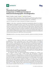
Theoretical and Experimental Comparison of Total Harmonic Distortion Factors for the Evaluation of Harmonic and Interharmonic Pollution of Grid-Connected Photovoltaic Systems Massimo Aiello, Antonio Cataliotti, Member, IEEE, Salvatore Favuzza, and Giorgio Graditi
Abstract—Grid-connected photovoltaic systems are increasingly used in electrical distribution systems. However, they inject distorted currents. Therefore, special attention must be paid to harmonic and interharmonic measurements. The new edition of IEC 61000-4-7 introduces the concept of harmonic and interharmonic groups, which implies new expressions for total harmonic distortion (THD) factors. In this paper, a theoretical and experimental comparison is made between the different THD factors in order to show which of the currently defined distortion factors is best suited to detect harmonic and interharmonic pollution. Experimental tests were carried out first by means of a calibrator and subsequently in a single-phase grid-connected photovoltaic system. In both cases, measurements were carried out with a PC-based instrument developed by the authors and able to calculate the distortion factors according to IEC 61000-4-7. Index Terms—Grid-connected photovoltaic systems, harmonic and interharmonic analysis, IEC 61000-4-7 Ed 2002.
I. INTRODUCTION
T
HE widespread use of renewable sources in the generation of electrical energy and the increased penetration of distributed generation has led to a growing interest in electrical distribution systems. On the other hand, the presence of a large number of grid-connected systems creates new problems related to safety and protection systems, the grid interface, and power quality. Among renewable sources, one can note the widespread use of single-phase grid-connected photovoltaic (PV) systems for low power level, installed near customers [1]. From the point of view of power quality, the goal is to obtain a sinusoidal current as the output of the grid-connected PV system. Unfortunately, harmonics are present in the output current because of the use of power semiconductor devices and the variable power flow of the PV panels. Furthermore, the grid usually supplies many nonlinear loads, which absorb distorted currents [2]. These currents, flowing through the impedances of the power distribution system (variable with frequency), result in a distortion of system bus voltage [3]. Manuscript received January 19, 2005; revised May 13, 2005. Paper no. TPWRD-00027-2005. M. Aiello, A. Cataliotti, and S. Favuzza are with the Dipartimento di Ingegneria Elettrica, Universitá di Palermo, Palermo 90128, Italy (e-mail:
[email protected];
[email protected];
[email protected]). G. Graditi is with Ente per le Nuove Tecnologie, l’Energia e l’Ambiente, Napoli 80055, Italy (e-mail:
[email protected]). Digital Object Identifier 10.1109/TPWRD.2005.860231
Moreover, interharmonic components may be present because the power-electronic devices of photovoltaic systems usually have switching frequencies not synchronized with the supply frequency. As is well known, the possible effects of interharmonics are noise in audio amplifiers, additional torques on motors and generators, additional noise in inductive coils (magnetostriction), and the blocking or unintended operation of ripple control receivers. In addition, they may affect synchronization techniques, such as phase-locked loop (PLL) or methods based on spectral analysis, used for synchronous sampling in instrument applications and for the synchronization with the power frequency in devices such as uninterruptible power supplies (UPS), active filters, and grid-connected devices [4], [5]. Therefore, interharmonics are an important class of power systems phenomena [6]. Consequently, the high level of distortion in currents and voltages has made necessary the improvement of the definitions of limits in power systems and the standardization of analysis procedures that are able to ensure an accurate monitoring of harmonic and interharmonic distortion in power networks. Presently, the IEC 61 000-4-30 standard gives a complete view of testing and measurement techniques for power quality [7]. This standard, as well as the international standards for testing and measurement techniques for electromagnetic-compatibility (EMC) problems and power system networks, refers to IEC 61 000-4-7 [8] to define harmonics and interharmonics measurements. A revision published in August 2002 defines accuracy limits, measurement procedures and requirements for harmonic and interharmonic measurement instrumentations up to 2 kHz (or 9 kHz). Usually, voltage and current are not stationary, but it is always useful to obtain their distortion analysis. Also, in the standard IEC 61 000-4-7, a new concept is introduced: the spectral lines grouping. Furthermore, the standard defines some distortion factors: the well-known total harmonic distortion (THD), the group total harmonic distortion (THDG) and the subgroup total harmonic distortion (THDS). In order to restrict spectral leakage only to nonstationary signal and to ensure repeatable and comparable results, the limits for the synchronization of the sampling frequency set by the standard are very tight. It can be observed that International and European standards on grid-connected PV systems refer currently only to the THD factor to evaluate the amount of harmonic distortion. Moreover,
0885-8977/$20.00 © 2006 IEEE
AIELLO et al.: THEORETICAL AND EXPERIMENTAL COMPARISON OF TOTAL HARMONIC DISTORTION FACTORS
instruments currently available on the market are often not updated to the above-mentioned new standard and calculate only the THD factor. Finally, it is useful to study which of the currently defined distortion factors is best suited to detect harmonic and interharmonic pollution. The aim of this paper is to present a theoretical and experimental comparison of the various THD factors in order to show how the new definitions allow one to achieve a better understanding of the harmonic and interharmonic pollution of a gridconnected PV system. First, a review of international and European standards on grid-connected PV systems is presented. Second, the new approach of the line grouping and the different THD factors are introduced. Third, in the paper, the performances of the harmonic distortion factors are analyzed by means of a PC-based instrument proposed by the authors in agreement to IEC 61 000-4-7, a commercial power analyzer and a power calibrator. The last part deals with experimental tests carried out on a single-phase grid-connected PV system, installed on a roof footbridge at the Faculty of Engineering—University of Palermo, by comparing the measurement results obtained by the PC-based instrument with a commercial power analyzer. II. TECHNICAL STANDARD FOR PV GRID-CONNECTED PLANTS The IEEE standard 929-2000 “Recommended practice for utility interface of photovoltaic systems” contains guidance regarding the equipment and functions necessary to ensure the compatible operation of PV systems that are connected in parallel with the electric utility (personnel safety, equipment protection, power quality, and utility system operation). With respect to the power quality of the PV system output, the IEEE standard 519-1992 “Recommended Practices and Requirements for Harmonic Control in Electrical Power Systems” sets limits of harmonic voltage and current at the point of common coupling (PCC). This standard establishes limits equal to 5% for the current and voltage THD factors that the producer should deliver to the customer. This standard also gives individual harmonic limits as the percentage of the fundamental frequency component at full system output. The IEC standard 61727 (European standard EN 61727) “Photovoltaic (PV) systems—Characteristics of the utility interface” addresses the interface requirements between PV systems and the utility, and provides technical recommendations. With regards to power quality and, in particular, to harmonics, the standard says that low levels of current and voltage harmonics are desirable. When harmonic limits are defined, the THD factor is always taken into consideration. In particular, different limits are given for the current, 5% for total current harmonic distortion (THDI), and the voltage, 2% for total voltage harmonic distortion (THDV) with a 1% maximum for individual voltage harmonics. The European standard EN50160 “Voltage characteristics of electricity supplied by public distribution systems” provides a limit for the total voltage harmonic distortion equal to 8%, including up to the 40th harmonic. Moreover, limits for individual voltage harmonics are specified. As an example, in Italy, too, harmonic limits are given by considering only the THD factor. The Italian technical standard
1391
CEI 11-20 (Italian Electrotechnical Committee) “Electrical energy production system and uninterruptible power systems connected to I and II class network” provides the criteria that can be applicable to all electrical energy production systems and also to PV plants including grid interface and protection devices and systems. Moreover, in Italy, in connecting the PV plants to the public electrical grid, the document DK 5950 “PV plants connection criteria to low voltage electrical distribution systems” edited by ENEL (Italian electrical utility) must be considered. III. THD FACTORS ACCORDING TO IEC 61000-4-7 The new distortion factors according to IEC 61 000-4-7 are based on the concept of spectral line grouping. Therefore, in the following paragraph, a brief review of this concept is presented. As is well known, the calculated spectrum is equal to the real one, only if the analyzed signal segment is stationary and if it is an integer multiple of its period, which means using a sampling frequency multiple of the fundamental signal frequency [9]. Otherwise, a spread of signal spectral components (i.e., leakage) over closed bins is obtained. The synchronization of sampling reduces, but does not eliminate, the leakage error (i.e., the spreading out of the energy of harmonic components to adjacent spectral bins), due to the fluctuation of voltage and current signals in power systems. In order to improve accuracy and obtain comparable results, the standard [8] introduces the concept of grouping (i.e., the root mean square (rms) of different closed spectral lines and three different aggregation intervals). This procedure allows one to reduce the errors due to the presence of fluctuating harmonic and interharmonic components, which cause “sidebands” close to the harmonics [8], [10]. The standards [7], [8] define a signal observation window equal to 10–12 fundamental periods (50–60-Hz power systems) and, thus, the spectral resolution obtained is 5 Hz (Fig. 1). These lines are grouped by evaluating the rms in different configurations, groups, or subgroups, depending on what kind of measurement is to be performed (harmonics or interharmonics or both). The harmonic group component of order , corresponding to the central line in the hatched area (Fig. 2), has the magnitude (rms value). of is obtained by summing squared intermediate lines between two adjacent harmonics according to (1) for 50-Hz and to (2) for 60-Hz systems, as visualized in Fig. 2. 50-Hz systems
(1) 60-Hz systems
(2)
where is the value of the central line of the fast Fourier transform (FFT) (Fig. 2) corresponding to the harmonic, and
1392
IEEE TRANSACTIONS ON POWER DELIVERY, VOL. 21, NO. 3, JULY 2006
Fig. 1. General spectrum resolution according to IEC 61 000-4-7 (represented here for a 50-Hz system).
Fig. 2.
Fig. 3. Illustration of interharmonic groups (represented here for a 50-Hz system).
Illustration of harmonic groups (represented here for a 50-Hz system).
are the values corresponding to the spectral lines (five on the left and five on the right side for 50-Hz systems, or is the amplitude six and six for 60-Hz ones) subsequent to it. is the width of a spectral of the observation window and bin, 5 Hz. A similar evaluation is used for interharmonics. Moreover, their components usually do not vary in magnitude, but also in frequency. A grouping of the spectral components in the interval between two consecutive harmonic components forms an interharmonic group. The interharmonic groups are evaluated according to (3) and (4) and are shown in a graph in Fig. 3. For 50-Hz systems
Fig. 4. Illustration of interharmonic groups (here represented for a 50-Hz system).
Interharmonic subgroups for 50-Hz systems
(6)
and for 60-Hz ones
(7) (3)
and for 60-Hz ones (4)
The effects of fluctuations of harmonic components that cause sidebands close to the harmonics are partially reduced by excluding from interharmonic groups the lines immediately adjacent to the harmonic frequencies. The interharmonic components and nine (50-Hz systems) or 11 (60-Hz systems) directly adjacent to a harmonic are grouped to form a harmonic subgroup according to (5), whereas to eight or ten) the remaining interharmonic components ( form the centered interharmonic subgroup according to (6) and (7). Fig. 4 gives a clear idea of the different lines, grouped to form harmonic and interharmonic subgroups. Harmonic subgroups for 50- and 60-Hz systems (5)
If only harmonics are evaluated, the grouping procedure applies. If harmonics and interharmonics are evaluated separately (e.g., for the assessment of equipment prone to produce interand 9 or harmonics), the interharmonic components ( 11) directly adjacent to a harmonic are grouped to form a harmonic subgroup, according to (5), whereas the remaining interto 8 or 10) form the interharmonic harmonic components ( subgroup according to (6) or (7) [8]. As stated in the introduction, the IEC 61 000-4-7 defines some distortion factors, the well-known THD and two new factors deriving from the definition of groups and subgroups: the THDG and the THDS. The THD factor is defined as the rms value of the harmonics to the rms value of the fundamental
(8) As can be easily understood, the main problem of the THD is that it does not take into account either the effects of fluctuations of harmonic components or the interharmonic contribution to the signal distortion.
AIELLO et al.: THEORETICAL AND EXPERIMENTAL COMPARISON OF TOTAL HARMONIC DISTORTION FACTORS
1393
The THDG factor is evaluated as the THD; however, referring to the harmonic groups instead of the central harmonic line, as shown by (9), applicable to both 50- and 60-Hz systems
(9) The THDG is better able to represent harmonic and interharmonic signal distortion taking into account the presence of interharmonics. However, it is referred to the group of the fundamental and not only to the fundamental component or to the fundamental subgroup. Therefore, in the case of interharmonic components close to the fundamental, the THDG could be reduced without giving correct information on interharmonic pollution. The second factor is the THDS, which is evaluated in the same way as the THDG but referring to the harmonic subgroups. The implemented formula is reported for 50- and 60-Hz systems in (10)
Fig. 5. Test bench.
(10) Fig. 6. Functional block diagram of the harmonic and interharmonic measurement instrument.
THDS is better able to represent only harmonic signal distortion, taking into account the effects of fluctuations of harmonic components that cause sidebands close to the harmonics. However, it does not consider the presence of interharmonics between two consecutive harmonic frequencies. IV. EXPERIMENTAL COMPARISON BETWEEN THD INDEXES BY MEANS OF A POWER CALIBRATOR One can observe the absence in the standard of a distortion factor related to interharmonic groups or subgroups. A possible reason might be that both IEC 61 000-4-30 and IEC 61 000-4-7 do not refer explicitly to distortion factors because the assessments of voltage and current harmonic and interharmonic emissions are performed by harmonic groups and interharmonics subgroups, respectively. On the contrary, as shown in the section on technical standards for PV systems, the assessment of compliance with emission limits usually should be performed by THD factor. Therefore, in order to show the performances and the limitations of the different distortion indexes in the presence of voltage or current signals distorted by harmonics and interharmonics, an experimental comparison was carried out. Test signals, with different harmonic and interharmonic content, were generated by means of a monophase power calibrator Fluke 61 000 A electrical power standard, whose specifications are a voltage range up to 1000 V, a current range up to 20 A with voltage and current accuracies of 100 ppm. The distortion factors were evaluated with a commercial power analyzer Fluke 41B power harmonics analyzer and a PC-based instrument for harmonic and interharmonic measurements, developed by the authors according to IEC 61 000-4-7 and IEC 61 000-4-30. The commercial analyzer calculates only the THD factor. In Fig. 5, the test bench is reported.
The PC-based instrument was based on FFT aalysis and was composed of two main parts: the synchronizer and the measurement blocks. The functional block diagram is reported in Fig. 6. Current and/or voltage signals were transduced by means of a voltage differential probe (bandwidth up to 100 MHz, accuracy 3%) and a Hall effect current probe (bandwidth dco 100 kHz, analog output 100 mV/A, accuracy 1%). In order to avoid aliasing error, a low-pass filter, realized by an active Butterworth filter of the eighth order with a cut frequency set to 2.5 kHz, was applied to all of the transducer outputs before the sampling process. The transducer outputs were sampled according to the CZT-based synchronizer and the FFT was applied to obtain the values of each frequency component. The implemented CZT-based synchronizer checks the sampling process in order to evaluate the respect of the synchronization condition (i.e., the observation window has to be a 10–12 fundamental period with a maximum permissible error equal to 0.03%). If this condition is not respected, the system weighs the signal observed window with the Hanning function before proceeding with the harmonic and interharmonic analysis. The instrument has been set to measure harmonic and interharmonic components in the range of 0 to 2 kHz for a 50-Hz power electric systems. It can also be set for 60 Hz, thus setting the nominal frequency in the control panel. According to [8] and as required by emission standards (IEC 61 000 Part. 3), the FFT lines are grouped as previously described in different configurations in order to evaluate the harmonic groups and subgroups, the interharmonic groups and subgroups, and the THD, THDS, and THDG distortion factors. The evaluated distortion factors, as required by [7] and [8], were smoothed in order to neglect the variation of the current and voltage spectral
1394
TABLE I TEST SIGNAL FEATURES AND FACTORS MEASURED FOR THE FIRST TEST
content. The average algorithm in accordance with [7] and [8] was based on a 10-min time interval. The instrument was developed by means of Labview 6.1 running on a personal computer and a 12-b National Instruments PCI-MIO-16E-4 data-acquisition (DAQ) board. The implementation of the virtual instrument makes it possible to modify measurements parameters according to customer requirements or to standards evolution. Regarding accuracy, the instrument is of class I and also when it is coupled with a commonly used voltage or current transducer, according to [8]. A complete description of the instrument and of its accuracy evaluation are reported in [10]. The following paragraphs report the tests conditions and the distortion indexes obtained. The first test signal was generated by the calibrator with the fundamental component at 50 Hz and two harmonic components (second—100 Hz, and fourth—200 Hz) as reported in Table I, where the distortion factors evaluated by the PC-based istrument and by the Fluke 41 are also reported. As shown, the values of the various distortion indexes do not show any difference between themselves or between the two instruments because of the absence of interharmonics. The second test signal was composed by the fundamental component at 50 Hz, two harmonic components (second—100 Hz and fourth—200 Hz) and an interharmonic at 158 Hz close to the third harmonic. Its energy leaks mainly on the 155-Hz and 160-Hz spectral lines because the spectral resolution is 5 Hz. Therefore, the energy of the interharmonic component influences both the third harmonic subgroup and the third interharmonic subgroup. The features of the test signal and the factors measured are reported in Table II. As previously remarked, the THD, calculated by means of the , does not take into account only harmonic spectral lines the distortion due to the interharmonic component. On the contrary, the THDS and the THDG feel the effect of this interharmonic component. The harmonic subgroup includes only partially the interharmonic component energy while the harmonic group contains all of it, so that the THDS is lower than the THDG. In the third test condition, only the frequency of the interharmonic component was changed at 170 Hz, so as not to affect any harmonic subgroup. The amplitude of the harmonic and interharmonic signal components was not modified so that the behavior of the different distortion indexes could be observed more
IEEE TRANSACTIONS ON POWER DELIVERY, VOL. 21, NO. 3, JULY 2006
TABLE II TEST SIGNAL FEATURES AND FACTORS MEASURED FOR THE SECOND TEST
TABLE III TEST SIGNAL FEATURES AND FACTORS MEASURED FOR THE THIRD TEST
clearly. The features of the test signal and the measurement factors are reported in Table III. In this case, the THD and the THDS, including the same spectral components, calculate the same value as the first test. The THDG still detects the presence of an interharmonic because it takes harmonic groups into account. V. EXPERIMENTAL TESTS ON A SINGLE-PHASE GRID-CONNECTED PV SYSTEM The experimental tests were carried out on a 2.9-kWp PV plant, installed on the roof footbridge at the University of Palermo, Faculty of Engineering, as shown in Fig. 7. The single-phase PV plant is connected to the public lowvoltage electrical distribution network (230 V, 50 Hz). The PV plant is composed of two 1.45-kW subarrays, that can work independent of each other. A subarray is composed of two strings, each having six PV modules connected in series. The electrical features of each string are the following: • number of modules 6; • string peak power 725 (W ; • open-circuit voltage (V 228.6 V; • short-circuit current (I 4.6 A; • maximum power voltage (V 186 V; • maximum power current (I 4 A. The electrical features of each subarray are the following: • number of strings 2; • subarray peak power 1450 W ;
AIELLO et al.: THEORETICAL AND EXPERIMENTAL COMPARISON OF TOTAL HARMONIC DISTORTION FACTORS
Fig. 7. View of the PV plant used in the research.
TABLE IV INVERTER DATA SHEET
• open-circuit voltage (V 228.6 V; • short-circuit current (I 9.2 A; • maximum power voltage (V 186 V; • maximum power current (I 8 A. The PV plant is interfaced with the public low-voltage electrical distribution network by means of two Sunrise MIDI PLUS–Fronius inverters (an inverter for each subarray); the inverters are paralleled in a panel. The data sheet of the inverter is reported in Table IV. The PV plant is equipped with an array panel, an electrical board containing the two inverters, the data transmission and acquisition system, the grid interface device (DV 606), array fuses, circuit breakers, and tie-switches; another panel is also present, where the output of the inverters is interconnected to the grid (Fig. 8). The grid interface device DV 606 prevents any undesired islanding working conditions. The distortion factors were evaluated by means of the commercial power analyzer Fluke 41 and the PC-based instrument developed by the authors according to IEC 61 000-4-7. In Fig. 8, the PV plant and the measurement system scheme are shown. Three working conditions were considered. The first condition was with both inverters connected to the grid. The current and voltage waveforms are reported in Fig. 9, while the resulting spectra are shown in Fig. 10. In the second condition, only one inverter was switched on. In the last condition, both inverters were switched off. Test conditions are reported in Table V, where P stands for is the the active power generated, R is the solar radiation, average temperature measured, V is the voltage measured in
Fig. 8.
1395
PV plant scheme and the measurement system.
the point of coupling between the photovoltaic system and the is the generated current measured by the power line, and I photovoltaic system for the first (PV1) and the second (PV2) panel. Table V also shows the distortion factors measured by means of the commercial power analyzer Fluke 41 (THD) and the PC-based instrument (THD, THDG, THDS). Moreover, in Figs. 11 and 12, the distortion factors of the current and of the voltage, evaluated by the PC-based instrument, are compared by means of histograms. It can be observed that, as expected, the three indexes are different in agreement with the experimental comparison performed by means of the power calibrator. The THD does not take into account the distortion due to the fluctuating harmonics and interharmonic components. Thus, it is always the lowest index. On the contrary, the THDS and the THDG feel the effect of interharmonic components. The THDS is lower, as expected, than THDG because the harmonic subgroups only partially include the interharmonic components, while the harmonic groups consider all of them. On the other hand, it can be observed from Fig. 10(a) that interharmonic components are present in the current spectrum adjacent to the fundamental. Therefore, the THDG gives only partial information on interharmonic pollution because it is referred to the group of the fundamental but not only to the fundamental component or to the fundamental subgroup. VI. CONCLUSION In this paper, the authors have presented a theoretical and experimental comparison between the different THD indexes, defined by IEC 61 000-4-7, in order to show their performances and their limitations in the evaluation of the harmonic and interharmonic pollution of a grid-connected PV system. The experimental comparison was carried out by means of a PC-based instrument developed by the authors and a commercial power analyzer. Test signals generated by a power calibrator have allowed one to show how both the THD and the THDS are unable to detect the presence of interharmonic components. On the contrary, the THDG is well suited to detect the presence of interharmonics components, because of the approach of the spectral lines grouping. The evaluation of the three distortion indexes carried out in a PV plant agrees with the expected results.
1396
IEEE TRANSACTIONS ON POWER DELIVERY, VOL. 21, NO. 3, JULY 2006
Fig. 9. First condition: (a) current and (b) voltage waveforms.
Fig. 10. hertz.
First condition: (a) current and (b) voltage spectra (zoomed on the main components). FFT components must be multiplied by 5 Hz to be represented in
TABLE V MEASUREMENT RESULTS BY VARYING THE NUMBER OF CONNECTED COMPONENTS
Moreover, it has been shown how the technical standards for PV systems refer only to the total distortion factor for the assessment of compliance with emission limits. This implies that the influence of interharmonics components is not taken into due consideration.
Finally, it can be observed that the THDG is referred to the group of the fundamental and not only to the fundamental component nor to the fundamental subgroup. Therefore, in the case of interharmonic components close to the fundamental, the THDG could be reduced without giving correct information
AIELLO et al.: THEORETICAL AND EXPERIMENTAL COMPARISON OF TOTAL HARMONIC DISTORTION FACTORS
1397
[3] W. M. Grady and S. Santoso, “Understanding power system harmonics,” IEEE Power Engineering Rev., vol. 21, no. 11, pp. 8–11, Nov. 2001. [4] M. Aiello, A. Cataliotti, V. Cosentino, and S. Nuccio, “Synchronization techniques for power quality instruments,” in Proc. Instrumentation Measurement Technology Conf., Como, Italy, May 18–20, 2004. [5] M. Aiello, A. Cataliotti, and S. Nuccio, “A chirp Z transform based synchronizer for power system measurements,” IEEE Trans. Instrum. Meas., vol. 54, no. 3, pp. 1025–1032, Jun. 2005. [6] IEEE Interharmonic Task Force, Cigrè 36.05/CIRED 2 CCO2 Voltage Quality Working Group, Interharmonics in Power Systems. [7] Testing and Measurement Techniques—Section 30: Power Quality Measurement Methods, IEC Std. 61 000-4-30, 2003. [8] Testing and Measurement Techniques—Section 7: General Guide on Harmonics and Interharmonics Measurement and Instrumentation for Power Supply Systems and Equipment Connected Thereto, IEC Std. 61 000-4-7, 2002. [9] A. V. Oppenheim and R. W. Shafer, Digital Signal Processing. Upper Saddle River, NJ: Prentice-Hall. [10] M. Aiello, A. Cataliotti, and S. Nuccio, “A PC-based instrument for harmonics and interharmonics measurement in power supply systems,” Measurement, vol. 35, no. 4, pp. 371–380, Jun. 2004.
Fig. 11.
Current distortion factors for different test conditions. Massimo Aiello was born in 1972. He received the M.S. and Ph.D. degrees in electrical engineering in 1998 and 2003, respectively, from the University of Palermo, Palermo, Italy, where he is currently pursuing the Ph.D. degree. Currently, he is with the Research Group of Electrical and Electronic Measurement, University of Palermo. His research interests are digital signal processing, power-quality instrumentation and characterization, and harmonic and interharmonic measurements.
Antonio Cataliotti (M’01) was born in 1967. He received the M.S. and Ph.D. degrees in electrical engineering from the University of Palermo, Palermo, Italy, in 1992 and 1998, respectively. Currently, he is an Associate Professor in electrical measurements with the Department of Electrical Engineering, University of Palermo. His research interests include electrical drives control and diagnostics, digital signal processing, testing of electrical machines and drives, power-quality measurements, and detection of sources of disturbances in power systems. Fig. 12.
Voltage distortion factors for different test conditions.
on interharmonic pollution. Work in progress is directed toward both the definition of new distortion indexes which avoids the drawbacks of the defined distortion factors and the analysis of the variations of harmonic and interharmonic pollution of grid-connected PV systems, by varying the solar radiation and, thus, the working conditions of the inverters.
Salvatore Favuzza was born in 1969. He received the Ph.D. degree in electrical engineering from the University of Palermo, Palermo, Italy, in 2000. Currently, he is a Researcher in the Department of Electrical Engineering, University of Palermo. His research interests include applications of artificial intelligence techniques to the control of electrical power systems, power systems analysis, and optimal planning, design, and control of electrical distribution systems.
REFERENCES [1] G. Graditi, T. Contardi, A. Sarno, A. Scognamiglio, and F. Apicella, “ENEA’s activities in building integrated grid-connected PV systems,” in Proc. 18th Eur. Photovoltaic Solar Energy Conf. Exhibit., Rome, Italy, Oct. 7–11, 2002, pp. 1250–1254. [2] G. Graditi, S. Favuzza, E. R. Sanseverino, and G. Vitale, “An experimental analysis of power quality in presence of single phase grid connected photovoltaic systems,” in Proc. 19th Eur. Photovoltaic Solar Energy Conf. Exhibit., Paris, France, Jun. 7–11, 2004, pp. 2046–2049.
Giorgio Graditi was born in 1968. He is currently pursuing the Ph.D. degree in electrical engineering from the University of Palermo, Palermo, Italy. Currently, he is a Researcher with the Italian National Agency for New Technologies, Energy and Environment (ENEA), Portici Napoli, Italy. His research interests are in the areas of applications of photovoltaic power systems, power systems analysis, and optimal planning, design, and control of electrical distribution systems.