Several illustrations indicate that this model, in contrast to other models, can .... ILLUSTRATION 1: TRAINING AND THE THERMOMECHANICAL BEHAVIOUR.
JOURNAL DE PHYSIQUE W Colloque C8, supplkrnent au Journal de Physique III, Volume 5, dCcembre 1995
C8-203
Thermodynamic Modelling of Shape Memory Behaviour: Some Examples R. Stalmans, J. Van Humbeeck and L. Delaey Department of Metallurgy and Materials Engineering, Catholic University of leuven, de Croylaan 2, 3001 Heverlee, Belgium
Abstract: This paper gives a general view of a recently developed thermodynamic model of the thermoelastic rnartensitic transformation. Unlike existing empirical, mathematical or thermodynamic models, this generalised thermodynamic model can be used to understand and describe quantitatively the overall thermomechanical behaviour of polycrystalline shape memory alloys. Important points of difference between this and previous thermodynamic models are that the contributions of the stored elastic energy and of the crystal defects are also included. In addition, the mathematical approach and the assumptions in this model are selected in such a way that the calculations yield close approximations of the real behaviour and that the final mathematical equations are relatively simple. Several illustrations indicate that this model, in contrast to other models, can be used to understand the shape memory behaviour of complex cases. As an example of quantitative calculations, it is shown that this modelling can be an effective tool in the "design" of multifunctional materials consisting of shape memory elements embedded in matrix materials.
INTRODUCTION Shape memory alloys (abbreviated to 'sma') show a complex, non-linear thermomechanical behaviour with hysteresis. Moreover, this complex behaviour is influenced by many parameters such as: the alloy system, minor alloying additions, the processing and the thermomechanical history. Therefore, many empirical or quasi-empirical models have been proposed to compute the thermomechanical shape memory behaviour. However, these empirical models show usually important shortcomings. Many of those models are not much detailed: it is for example assumed that the transformation occurs at one definite temperature or stress, or the influence of hysteresis and thermomechanical history are not incorporated, etc. Moreover, calculations for specific cases can only be done after the experimental determination of many coefficients. The use of a different alloy, shape or loading mode generally requires the complete repetition of the data fitting. Probably the most important disadvantage of empirical models is the very restricted range of application. Many illustrations of erroneous extrapolations can be easily found in recent literature. Summarised, empirical models have not yet been very successful mainly due to the complex nature of shape memory behaviour. The thermoelastic transformation has also been the subject of many thermodynamic studies. However, most thermodynamic models also fail in computing the thermomechanical behaviour of polycrystalline shape memory alloys. The main reason for this failing is that most of these thermodynamic models have only been developed for very specific purposes such as the analysis of calorimetric measurements [I] or for very simple cases such as the behaviour of non-cycled single crystals 121. Therefore a generalised thermodynamic model is presented and illustrated by examples in the following paragraphs. A GENERALISED THERMODYNAMIC MODEL Only a brief summary of a generalised thermodynamic model is presented here. Details can be found elsewhere [3,4]. For simplicity a simple shape memory element is considered': a uniaxially loaded bar or wire, free of macro residual stresses, with a homogeneous temperature T. The small volume change during transformation is neglected. Plasticity and other irreversible contributions are not considered in this paper. This is done for simplicity. Derivations for other systems can be performed along identical lines. Article published online by EDP Sciences and available at http://dx.doi.org/10.1051/jp4:1995827
JOURNAL DE PHYSIQUE IV
C8-204
Different from many other thermodynamic models, the thermodynamic contribution of crystal defects is taken into account in the present model. Crystal defects in the austenitic structure are inherited during the transformation by martensitic variants. The crystallographic orientation, the nature, and thus also the energy of the inherited defects depend on the orientation of the martensitic variants [5-71. Since the forward and reverse transformation are diffusionless, the original defects are obtained again after retransformation. The result is that the crystal defects in the austenitic structure favour the formation of those martensite variants in which the inherited defects have the lowest energy. Mathematically this defect contribution is introduced by the definition of the defect energy density gd, with dm the mass of the infinitesimal volume dV, and Xdv a summation on the defects in the volume dV: 111 gd = (lldm) * Xdv Rd Defects that have a significant influence on the thermomechanical behaviour, are the complex dislocation arrays generated in high densities by cycling through the transformation region. The mechanism of the two way memory effect (TWME) and new effects such as the work output during cooling have been explained based on the energetic contribution of these dislocation arrays [7-91. The different components of the 'elastic' energy stored in materials undergoing a thermoelastic transformation have also to be considered. The product of external stresses and the resulting elastic strains yield elastic strain energy. The elastic accommodation of the shape changes during transformation also result in elastic strain energy. Since the martensite-austenite interfaces are highly coherent, the contribution of the interface energy can in general be neglected with respect to the elastic strain energy. Mathematically this elastic contribution is introduced by the definition of the average elastic energy density g e ~with , Ge the total elastic energy stored in the system and M, the total mass of the system. gem = G& 121 Some notions and definitions have to be introduced. The variable x represents the martensite mass fraction. However, this internal variable only gives incomplete information on the strains linked with the transformation2. For that reason the volume function [x(r)] is introduced; [x(r)] represents in any point r the phase and the crystallographic orientation of the phase. Hence, this function also describes the martensite variant arrangement. The change of a function f during transformation is represented by Af; e.g. Aew(mj-a) represents the transformation strain Iinked with transformation from austenite to the martensite variant m,. The average of the function f on all martensite-austenite interfaces dA is represented by f ZA: ILP*dYd~ 131
~ Z A =
jL*dYdA where ZA represents a summation on all martensite-austenite interfaces dA; dy represents an infinitesimal displacement perpendicular to dA; and p the local mass density. The global equilibrium condition for this system can be deduced from the first and second law of thermodynamics, with gch the chemical free energy. 141 Agch(m-a) - Zg([xI) = 0 The three non-chemical free energy terms are combined in the global Zg-factor: 151 Z,([xl) = Aga~(Ex1)- a g e ~ / a x+ (1/~o)*~*AetrZA([~l) where AwA([x]), resp. AewZA([x])represents the change during transformation of the average defect energy density, resp. the average transformation strain, on all austenite-martensite interfaces corresponding with a transformation fraction [x]; p, is the mass density in the unloaded condition. From the equilibrium condition it can be deduced that in any point of the transformation front these martensitic variants are formed which correspond to a maximum Z-factor. The Z-factor (see 151) is composed of three non-chemical free energy terms: a defect term {AgaA([x])}, an elastic term {a&Mla~} and a work term {(llpo)*o*AewzA([x])). The influence of these three almost temperature independent terms on the selection of the martensite variants can be summarised as follows: (i) the defect term favours the formation of the variants which have been repeatedly induced during previous transformation cycles [7], (ii) the elastic term is minimum for the self-accommodating variants and favours the formation of a self-accommodating variant arrangement, and (iii) the work term is proportional to the transformational
-
' In many papers it is incorrectly stated that the shape memory strain is directly proportional to the martensite mass fraction.
work; this term favours the formation of the variants showing a maximum transformational work. It can be remarked that most thermodynamic models (see e.g. [2,10]) only take into account the variant dependency of the work term, and consequently have a very limited field of application. A generalised Clausius-Clapeyron equation can be obtained by differentiating the global equilibrium condition (141) at a constant transformation fraction [XI, with As the entropy change during transformation from austenite to martensite. Important to notice is that this equation cannot be applied when [x] fluctuates. Another important remark is that the transformation strain in the numerator is not an alloy constant: AeWzA([x])decreases in general with increasing x and is also influenced by other factors, including the heat treatment and the thermomechanical history.
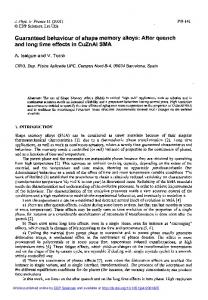
ILLUSTRATION 1: TRAINING AND THE THERMOMECHANICALBEHAVIOUR The result of the training procedure is that the defect term favours the formation of the variants which have been repeatedly induced. Based on this defect contribution the mechanism of the TWME can be explained, as discussed into detail in [3,7,9]. From the insights in the thermodynamic contribution of the defects, the hypotheses were deduced that samples showing the TWME can do a substantial amount of work during cooling, and that 'cold shape' recovery stresses can be generated during constrained cooling of trained samples [3]. Both new shape memory properties have been confirmed in different experimental studies [3,7-9,11,12]. Conversely, these experimental results clearly evidenced the importance of the defect contribution in a thermodynamic analysis. The details of the relationships between the training procedure, the TWME, the work output during cooling, and the generation of cold shape recovery stresses can also be explained by use of this generalised thermodynamic model [3]. ILLUSTRATION 2: STRESS GENERATION DURING CONSTRAINED HEATING The general procedure that can be followed in the case of constrained heating is illustrated by the example of the sma-composite beam depicted in figure 1. This beam shaped element is composed of straight sma-wires uniformly distributed in a matrix material. The external uniaxial forces acting on this hybrid element are divided into a constant force Fc and a linear bias force with spring constant k. A completely rigid, resp. free element can be modelled by taking the spring constant equal to infinity, resp. zero. The recoverable deformation of the sma wires at zero stress at the starting temperature To, which is below Mf, is given by e , ~ . The task is to calculate the stresses and strains in the hybrid element and in the composing elements during homogeneous heating, starting from To. The methodology and symbols are explained in figure 2. The total strain, e,, of the sma wires can be subdivided into a recoverable shape memory strain e,,, a thermal dilatation e,, and an elastic strain e,,. 171 e, = e,,+ e,, + e,= e, + a,*(T-To) +E,*o, with o, the stress in the sma-wires. The mathematics can be simplified by defining the corrugated shape memory strain e,, as: 181 e,, = e, -e,, = e,,+e,, A general boundary condition for this sma-composite beam can be easily deduced from the equations that express stress and strain equilibrium. 191 e, = e,o + b * ( T - To) + {F, - k*L*%*(T-To) - o,*Q,}/(Em*Qm + k*L) Since the transformation fraction [x] is not constant during constrained heating, the conditions for using the Clausius-Clapeyron equation (161) are not fulfilled. Yet, the stress-temperature relations can still be derived indirectly from 16 1. An infinitesimal temperature increase dT of the shape memory wires induces a stress increase do, and a strain change de,,. This infinitesimal step from A (T, o,, e,,) to C (T+dT, o,+do,, e,,+de,,) can be also achieved in two intermediate steps, as indicated in figure 3.
JOURNAL DE PHYSIQUE IV
system parameters *cross section of the matrix Q, .total cross sectionof the sma wires Q, *bias force Fc *bias spring constant k startingoftemperature *length the hybrid element To L
material parameters sma-wires *thermal dilatation coefficient a, *YoungsYmodulus E,
,IE *thermal dilatation coefficient a, *Youngs' modulus Em
sma parameters {strain eso - temperature TI-data *doJdT for a low and high value of e,, at o, equal to 25 MPa *pseudoelasbcmodulus P
4
Drogram sma-hvbrid
1
]stresses and strains of the hybrid element, sma wires and matrix during heating, e.g. fig. 5-8
1
Figure 2: schematic view of the procedures in the calculations of the stresses and strains during heating of the sma-composite beam, with definition of the symbols.
+
.a..-....
dT
-
...._........----strain esc
>
Figure 3: A temperature increase dT at the imposed boundary conditions results in a stress increase do, and a strain change de,, (A+C). This proces can be divided into two steps: (i) a temperature increase dT at a constant transformation fraction [x] yields a stress increase,dq, and an increase of the elastic strain by de, (A+B); (ii) a pseudoelastic unloading by dcp, at constant temperature {T+dT} results m a decrease of strain by d% (B+C).
It follows that the the stress increase do,, resp. strain change de,,, is also equal to the sum of do, and do , resp. dee and d ~ p .The stress increase do, from A to B follows from the Clausius-Clapeyron equation The pseudoelastlc unloading from B to C can be approximated by, with P, the slope dolde (fig.4): dop = P, * d% 1121 Finally, from 161,1111,and 1121follows the differential constitutive equation for this system:
14.
This differential equation allows to compute the stresses and strains obtained at incremental steps of the temperature T, starting from To. The stress in the sma-wires, o,, is obtained directly from 1131. The strain e, can be calculated from 1111. The different strain components of the sma-wires, e,, e,,, and e,,, follow from 171. The different stresses and strains of the matrix and of the hybrid element can be easily deduced from the equations expressing stress and strain equilibrium for this system. A simple Turbopascal program 'sma-hybrid' has been developed that by use of this differential equation calculates the stresses and strains in the hybrid element and in the composing elements during heating, as indicated in fig.2. The goal of this program is to calculate for a wide range of conditions the complex behaviour of sma-composite beams and, more general, of constrained sma-wires. The computations only require one set of simple to determine experimental data, as depicted in fig.4: (i) an array of {e,,-T} data measured by dilatometry), (ii) the slopes doJdT for a low and a high value of e,, during constrained heating of the sma wires, from which the term {po*As/AeazA([x])}in 1131 is estimated, This case refers to shape memory wires that have been trained to obtain a stable two way memory effect.
P1
S a, L
1
temperature
'
.... temperature
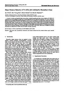
Figure 4: Schematic representation of the experimental sma-data required for the 'constrained recovery' calculations (i) array of strain-temperature points measured during stress-free heating, (ii) the two slopes doJdT at o, equal to 25 MPa for a low and a high value of e,o determined during heating at constant e,,, and (iii) the pseudoelastic modulus P, determined during pseudoelastic unloading. and (ui) the pseudoelastic modulus P, calculated from a linear approximation of the pseudoelastic unloading. Examples of computed results4for different conditions are shown in figures 5-8. Fig.5-6 show computed results for different values of e , ~ .Fig.7-8 shows results for different bias spring constants. A comparison of the computed results of fig.5 with the experimental results published in [3] shows an excellent quantitative agreement. Fig 7 and other calculated results also show that the slopes {do,/dT) of the recovery stress-temperature curves in the transformation region are hardly influenced by changes of the matrix characteristics, of the bias force or of the bias spring. This important finding has been confirmed by recent results obtained on Cu-Al-Ni single crystals. It implies that a simple addition of the separate contributions of a 'thermal' stress, a 'transformation' stress and an 'elastic' stress is incorrect in the case of constrained heating of shape memory elements, although this is the basic principle in many models published in recent literature on intelligent or smart materials.
CONCLUDING REMARKS A generalised thermodynamic model of a thennoelastic transformation has been formulated, taking into account the stored elastic energy and the energetic contribution of defects. In addition, the approximations and working out of the present model have been selected in such a way that the model is a close approximation of the real system and that the final mathematical expressions are relatively simple. In summary, this modelling offers a general framework for the understanding and calculation of shape memory behaviour. The computer programs are further developed and improved: (i) the equations have to be slightly modified when x becomes close to zero or one; a subroutine will be added to solve this problem, (ii) hysteresis can be formally included in this model and in the computer programs by adding to the equilibrium equation a term ek([x]) which expresses the irreversible contributions [3,4]. (iii) in the paper a constant P, is used to approximate pseudoelastic unloading; the results can be improved by replacing the constant P, by an array of { P,,e, } data. Acknowledgements R. Stalmans and J. Van Humbeeck acknowledge the N.F.W.O. (National Fund for Scientific Research, Belgium) for a grant as Postdoctoral Researcher, resp. Research Leader. References [I] J. Ortin and A. Planes, Acta Metall. 36 (1988) 1873-1889. [2] P. Wollants, M. De Bonte and J. R. Roos, Z. Metallk. 70 (1979) 113-117. [3] R. Stalmans, Doctorate Thesis, Catholic University of Leuven, Department of Metallurgy and Materials Science, Heverlee, Belgium (1993). [4] R. Stalmans, J. Van Humbeeck and L. Delaey, "A generalized thermodynamic model to predict shape memory behaviour", Mechanics of Phase Transformations and Shape Memory Alloys, AMDVOL.l89/PVP-VOL292, (ASME, Chicago, 1994), pp. 39-44. Data are taken from a trained Cu-base shape memory wire [3].
C8-208
JOURNAL DE PHYSIQUE IV
[5] M. Sade, A. Hazarabedian, A. Uribani and F. Lovey, 'Effects of cycling through stress-induced mart, transf. in Cu-Zn-A1 alloys on dislocation structures and two-way memory', Int. Conf. on Solid Phase Transformations,Ed. G . W. Lonimer (Inst. of Metals, Cambridge, 1988) pp. 279-281. [6] F. C. Lovey, A. Hazarabedian and J. E. Garces, Acfa metall. mater 37 (1989) 2321-2327. [7] R. Stalmans, J. Van Humbeeck and L. Delaey, Acta metall. mater. 40 (1992) 2921-2931. [8] R. Stalmans, J. Van Humbeeck and L. Delaey, Muter. Trans. JIM. 33 (1992) 289-293. [9] R. Stalmans, J. Van Humbeeck en L. Delaey, 'New insights into the mechanisms of the two way memory effect in copper based shape memory alloys', IUMRS-ICAM - Tokyo 93, Vol. 18B, Ed. K. Otsuka (Elsevier, Amsterdam, 1994) pp. 927-930. [lo] J.R. Pate1 and M. Cohen, Acta Metall. 1 (1953) 531-538. [ l l ] E. Cingolani, A. Yawny and M. Ahlers, 'The two way shape memory effect in stabilized and pseudoelastically trained Cu-Zn-Al single crystals', these proceedings. 1121 A. Amengual, E. Cesari and J. Pons, 'Characteristics of the two-way memory effect induced by thermomechanical cycling in Cu-Zn-Al single crystals', these proceedings
temperature in K
Figure 5: Calculated recovery stress-temperature relations for e , ~ from 1.04% to 0.06% in steps of 0.07 %. The material data are taken from a trained cu-base wire [3]. l-he boundary condition is given by: e,, = constant. Qm=O (no matrix material), To=350 K
temperature in K
Figure 7: Calculations of recovery stress temperature relations for different bias spring constants; ks in MPa/% strain; material data as in fig.5; e , = ~ 0.7%, To = 350 K, QJQ, = 1E7
0
temperature in K
Figure 6: Calculated sma strain (esr) temperature relations for the same conditions as in the figure on the left. An sma train equal to zero corresponds to the austenitic state.
temperature in K
Figure 8: Calculations of sma strain (esr) temperature relations for the same conditions as in the figure on the left.