Available online at www.sciencedirect.com
ScienceDirect Energy Procedia 78 (2015) 1762 – 1768
6th International Building Physics Conference, IBPC 2015
Thermoheliodome Testing: Evaluation Methods For Testing Directed Radiant Heat Reflection Emanuele Calabròa, Forrest Meggersb,c*, Eric Teitelbaumb, Hongshan Guob, Claire Gmachld, Germano Maioli Penellod a
IAUV University of Venice, Sustainable Constructive Processes, Venice, Italy b Princeton University, School of Architecture, Princeton, NJ, 08544, USA c Princeton University, Andlinger Center for Energy and the Environment, USA d Princeton University, Electrical Engineering, Princeton, NJ, 08544, USA
Abstract The Thermoheliodome is a prototype experimental pavilion that produces comfort through the manipulation of the mean radiant temperature generated by a combination of evaporative cooling and radiant heat reflection. We present the development of a sensing and analysis method for measuring the impact on radiant temperature and other performance data for the space, along with the initial system measurements. This is an environmental control station through which low cost microcontrollers enable distributed networked nodes to take measurements of relevant system parameters. The system measurements show a reduction of mean radiant temperature by 2-3 °C using evaporative cooling and strategic reflection. © 2015 The Authors. Published by Elsevier Ltd. This is an open access article under the CC BY-NC-ND license © 2015 The Authors. Published by Elsevier Ltd. (http://creativecommons.org/licenses/by-nc-nd/4.0/). Peer-review under responsibility of the CENTRO CONGRESSI INTERNAZIONALE SRL. Peer-review under responsibility of the CENTRO CONGRESSI INTERNAZIONALE SRL Keywords: environmental sustainability; prototyping; energy efficiency; arduino
1. Background 1.1. Motivation New methods to address environmental sustainability are needed, and interest in physical computing has risen dramatically over the last fifteen years in the fields of architecture, engineering, industrial design and art. Designers in
* Corresponding author. Tel.: +1-609-258-7831; fax: +1-609-258-4740. E-mail address:
[email protected]
1876-6102 © 2015 The Authors. Published by Elsevier Ltd. This is an open access article under the CC BY-NC-ND license (http://creativecommons.org/licenses/by-nc-nd/4.0/). Peer-review under responsibility of the CENTRO CONGRESSI INTERNAZIONALE SRL doi:10.1016/j.egypro.2015.11.298
Emanuele Calabrò et al. / Energy Procedia 78 (2015) 1762 – 1768
the future will be called upon to create spaces that are computationally enhanced. Rather than simply design traditional buildings with an outfitted computational layer, it is better to integrate design from the outset. There are few established methodologies for designing architectural spaces as smart or intelligent spatial systems. As such, it is clear that a new multidisciplinary approach is needed to integrate research and design across disciplines to create a holistic strategy for more livable and productive spaces. Preparing designers for these challenges demands a range of knowledge, skills, and experience well beyond the traditional domain of architectural education. 1.2. Thermoheliodome Construction During the Summer 2014 an outdoor space was designed and built to provide a cool and comfortable environment in Princeton, NJ summer by maximizing chilled surface area through which an occupant (or emitter) can exchange heat with radiantly. Referred to as the Thermoheliodome, this space is the prototype of an experimental pavilion that produces comfort through the manipulation of the mean radiant temperature generated by its surfaces instead of cooling the air, since air conditioning is impractical in an outdoor space. It consists of a series of 55 cones lined with reflective material that are set in 5 rows that traverse the robotically fabricated foam dome [1], whose form follows the sun path to achieve perfect shading on the summer solstice. At the center of each cone is a coaxial pipe that delivers chilled water to the focal line of the cone (see Fig. 1).
Fig. 1. Thermoheliodome System
Reflective cones are outfitted with pipes delivering indirect evaporative cooling from a wet cooling tower. Expanding the radiant cooling surface are via reflection is the objective, but radiant heat can also be supplied with heated water. An intelligent shape is generated that reflects the radiant temperature of each pipe everywhere inside the structure. Water is circulated through the dome’s bulb system, which positions the water along the focal line of the reflective cones, thereby reflecting the surface temperature of the bulb across the entire circle at the base of the cone. The only energy demand for cooling comes from the fan of the cooling tower and the water pump, which is on the order of 10 times less energy than compressor-based air conditioning. Through radiative heat exchange, the mean radiant temperature shifts the perceived comfort of users, allowing us to manipulate the sensation of hot or cold. The combination of the existing technologies will provide reliable operation and control of the radiant temperature in the space to facilitate research into the perceptions of comfort. Adjusting the mean radiant temperature felt by 1 degree creates the sensation of the air temperature changing by 1.4 degrees [2]. By designing a shaded pavilion with activated thermal surfaces, we demonstrated how integrated indirect evaporative cooling can generate new levels of comfort without relying on energy-intensive manipulation of air temperature and humidity through chillers for mechanical dehumidification in air conditioning. 2. Sensor Methods It is necessary to declare the physical parameters that represent the key components of this analysis. Sensors were installed to measure water flowrate (L/hr); outdoor air temperature (°C); outdoor relative humidity (%); cooling
1763
1764
Emanuele Calabrò et al. / Energy Procedia 78 (2015) 1762 – 1768
tower/water heater temperature (°C); Dome air temperature (°C); Dome relative humidity (%); Dome wind speed (m/s); Dome mean radiant temperature (°C). The digital "Dome Sensing and Control System” measures the physical parameters of the prototype. It’s an environmental control station through which Arduino or SparkCore platforms measure the conditions by receiving inputs from many sensors. Different kinds of sensors have been used to monitor these parameters: x x x x x x
DHT 11 - air temperature humidity sensor DHT 22 - air temperature humidity sensor DS18B20 – RTD water temperature sensor YF-S403 - waterflow sensor Omega Ceramic thermistor temperature sensors MLX Radiant Temperature Sensor
2.1. Mean Radiant Temperature Servo Station The MLX Radiant Temperature sensor was implemented in a novel way to measure the radiant temperature of the pavilion, compared to a standard black-globe thermometer. The system takes a weighted average reading while giving direction information for mean radiant temperature influences. The calculation of the mean radiant temperatures was performed by means of a MRT servo station, a tool built specifically to detect this physical quantity inside the Thermoheliodome. The MRT servo station consists of three components that work together. The first component is a continuous rotation servo used at the base of the station to perform complete revolutions of 360° on the xy (azimuthal) plane. The second component is a micro servo connected to the Continuous rotation servo through a platform. This servo is used to perform complete revolutions of 180° on the yz (angle of inclination) plane for the sensor. See Fig. 2.
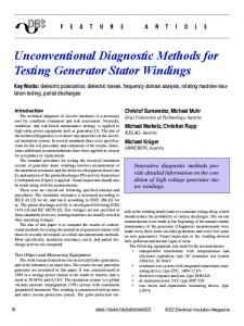
Fig. 2. (a) MRT Servo Station which moves a 5° field of view non-contacting infrared temperature sensor around test location (b) A conventional black-globe thermometer
In practice, the servo-station sensor provides directional data on mean-radiant temperature, which can be weighted to account for the transformation of the grid of data points plotted in Fig. 3 to a spherical surface. The sensor is noncontacting, so effects due to forced convection from wind do not impact data recorded from this sensor.
1765
Emanuele Calabrò et al. / Energy Procedia 78 (2015) 1762 – 1768
Fig. 3 shows the operation of the dome measured with the servo station mean radiant temperature sensor, before (a) and after evaporative cooling takes place (b). The mean radiant temperature drops noticeably, despite increase in surface temperature from an adjacent building due to solar gains. The directional information provided by this sensor for the dome is useful in design analysis, for instance sky exposure and influence of adjacent structure.
Fig. 3. (a) Infrared image generated from focal point of dome in Fig. 1 with cooling system off, MRT = 20.7 °C (b) Infrared image generated from same point after evaporative cooling has taken place. The coldest region is the sky, and the warmest regions are an adjacent building surface. Cooler surfaces are visible, MRT = 19.7°C
3.2 Black-globe Thermometer MRT can be measured using a black-globe thermometer shown in Fig. 2b, as is common practice in building sciences. The black-globe thermometer consists of a black globe with a temperature sensor probe placed in the center. The smaller the diameter of the globe, the greater the effect is of air temperature and air velocity on the internal temperature, thus causing a reduction in the accuracy of the measurement of the mean radiant temperature. The temperature sensor inside the globe measures the globe temperature (GT), tending towards thermal equilibrium under the effect of convection and radiation coming around the globe sensor. Knowing GT allows the mean radiant temperature MRT to be determined [2]. According to ISO 7726 Standard, the equation that is used most frequently for forced convection with known wind speed is the following: 1
MRT = (GT + 273) + 2.5×10⁸ ×va0,6 (GT − Ta ) 4 − 273 4
(1)
Where MRT is the mean radiant temperature (°C), GT is the globe temperature (°C), va is the air velocity at the level of the globe (m/s), İ is the emissivity of the globe, D is the diameter of the globe (m), and Ta is air temperature (°C). For the standard globe, D = 0.15 m and İ = 0.95. Moreover, since the MRT is defined with respect to the human body, the shape of the sensor is also a factor. The spherical shape of the globe thermometer gives a reasonable approximation of a seated person; for people who are standing, the globe, in a radiant nonuniform environment, overestimates the radiation from floor or ceiling, so an ellipsoid sensor gives a better approximation [3]. Data from the servo-sensor station can be weighted to fit an elliptical shape, another example of superiority for this novel sensor.
1766
Emanuele Calabrò et al. / Energy Procedia 78 (2015) 1762 – 1768
4. Data Collection System The combination of new and emergent technologies, such as Wifi-enabled SparkCores, enables remote observation and control of physical parameters. It presents a new technique for delivering thermal comfort and a system interface to observe the operation so as to facilitate research into the perceptions of comfort inside the Dome, and demonstrate the opportunity for this non-standard cooling and heating method. The Dome Control System consists of a software component and hardware components. Through the Arduino/SparkDev IDE a main script was written that contains all single scripts of each sensor. The main script is able to combine different codes characterized to different outputs for the analyzed physical quantities and create an output string parsed by JSON. 4.1. Board Configuration With a single board Arduino UNO Rev. 3 it was possible to combine eight different kind of sensors, all connected to a single microcontroller. The integrated system is able to monitor the prototype at all times, allowing one to investigate the physical investigation behind the Thermoheliodome. A fundamental step to achieve our target was the proper location of each sensor in the main system to control the sensible points of the Dome (see Fig. 4).
Fig. 4. Position of sensors
5. Data Collection results The average weather station data for the Fall of 2014 in Princeton, NJ reports a 22°C Dry Bulb temperature, 16°C Wet Bulb temperature and 10°C Dew Point temperature. Although the dome was designed for cooling in warm summer months, the completion of the dome at the end of summer prevented data collection during these months, which is why cooling data was taken during the fall. The Dome is designed as outdoor space, so we validated out sensors by monitoring the humidity inside the dome versus ambient humidity, etc. During all tests the flow rate through the piping system was monitored. The trend of the water flow of the plumbing system was roughly constant, characterized from 750 L/hour to 790 L/hour. Preliminary results of the cooling system show the ability of the prototype to reduce the mean radiant temperature inside the outdoor space.
1767
Emanuele Calabrò et al. / Energy Procedia 78 (2015) 1762 – 1768
Fig. 5 (a) Infrared image of cooling mode before water is circulated and (b) cooling mode at steady-state
Fig. 6a shows the relationships between dome, water, and mean radiant temperatures. The reflected surface temperatures is on average 4.1 °C cooler than the ambient temperature, for an overall MRT depression of 2-3 °C at the focal point of the dome. Mean radiant temperature here was sensed with the MRT Servo Station in Fig. 2a. Noise in the MRT data is large, and imply issues with the servo station method based on the starting point for its revolution. Despite a good reduction in water temperature due to evaporation, the temperature gradient in the PVC bulbs was large due to poor thermal conductivity of PVC. For the average depression observed of 6.5 °C in water temperature for instance, a surface temperature depression of 4.1 °C was typical, shown in Fig. 6a. Future pavilions will be designed with this result in mind, using a material such as copper or aluminum piping for the black bulbs, and will likely achieve lower mean radiant temperatures in cooling modes.
22
4
25
80
2
20
70
Air
0
Radiant Temp.
16
Water Temp.
14
12
°C Air Temp (Dome)
-4
Black Bulb Temp (GT)
°C
°C
-2
-6
30 0
20 10
-10 14:24
16:48
4:48
9:36
14:24
Humidity
40
5
-8
12:00
Return Water
50
10
-5 10 09:36
Water
60
15
Air Temp.
18
-10 0:00
12:00
0:00
% Relative Humidity
20
0 12:00
Fig. 6. (a) Cooling mode data recorded every 30 minutes (b) heating mode data from within the dome recorded every minute with (c) water and ambient conditions during heating mode
Additionally, system monitoring during heating mode in mid-January is shown in Fig. 6b and c. Water exiting the heater is consistently warmer than the return water temperature by 0.37 °C on average (green and purple in Fig. 6c). This value combined with an average water flow rate of 3,030 L/s over all 5 rows provides a 1300 kW value used for heating. Mean radiant temperature is consistently warmer than the ambient air temperature, however at night they equilibrate when conditions are windier, causing more convective heat loss. MRT data are collected with the GT pictured in Fig. 2b. Spikes in data at 14:24 on 01/16 indicate the system shut down due to the thermostat setpoint of 5 °C implemented to reduce energy consumption during testing, and to ensure heating was provided to prevent the system from freezing over. 6. Conclusions Implementation and development of new methods of calculation of the mean radiant temperature were successfully employed. Use of more powerful Arduino board through the construction of a wireless monitoring system that would provide results 24 hours through an Internet browser was also implemented towards the end of the monitoring. This
1768
Emanuele Calabrò et al. / Energy Procedia 78 (2015) 1762 – 1768
system allows us to fully understand the potential of the prototype, which has provided initial extremely satisfactory results: it recorded a decrease of 2-3 °C for the cooling system and an increase of 3-4 °C for the heating system. References [1] Read JR, Aschwanden G, Houchois N, Teitelbaum E, Meggers F. Thermoheliodome design, optimization and fabrication. In Proceedings of 6th International Building Physics Conference, IBPC 2015, Tornio, Number 902. [2] ISO 7726. Ergonomics of the thermal environment - Instrument for measuring physical quantities. Geneva, Switzerland: International Organization for Standardization. November 1998. [3] ASHRAE. 2009 ASHRAE Handbook Fundamentals. ASHRAE, Inc., Atlanta, GA.