Three-dimensional object reconstruction using phase-only information from a
digital hologram. O. Matoba,a T. J. Naughton,b Y. Frauel,c N. Bertaux,d and B.
Three-dimensional object reconstruction using phase-only information from a digital hologram O. Matoba,a T. J. Naughton,b Y. Frauel,c N. Bertaux,d and B. Javidic a Institute
of Industrial Science, University of Tokyo, 4-6-1, Komaba, Meguro-ku, Tokyo 153-8505, Japan b Department of Computer Science, National University of Ireland, Maynooth, County Kildare, Ireland c Department of Electrical and Computer Engineering, University of Connecticut, U-157, Storrs, Connecticut 06269-2157, USA d Domaine Universitaire de Saint-J´ erˆome, Ecole Nationale Superieure de Physique de Marseille, 13397 Marseille, France ABSTRACT We present the initial results of a novel technique that uses only phase information from a digital hologram for the reconstruction of three-dimensional (3D) objects. Our holograms are created using phase-shift digital holography. Perspectives of the 3D object are usually reconstructed numerically on a computer. For large holograms this can be a computationally intensive task. We believe that the proposed reconstruction technique is promising for 3D display because the phase-encoded digital holograms admit optical, and therefore realtime, reconstructions that use commercially available display devices such as liquid crystal spatial light modulators. Numerical evaluation of the reconstructed 3D object and an experimental demonstration are presented. Keywords: Optical data processing, three-dimensional image processing, computer holography, image reconstruction techniques
1. INTRODUCTION Holography is one popular choice among several techniques for the imaging and display of three-dimensional (3D) objects.1–6 Recently, digital holography7 has become a viable 3D imaging technique with the ongoing development of megapixel CCD sensors that have sufficient dynamic range in each pixel. It has been shown with numerical propagation that the fully complex field calculated from the digital holograms in the Fresnel domain can be used to reconstruct 3D objects successfully.7–10 Storage of the hologram in a computer enables us to reduce the noise through image processing techniques and numerically reconstruct the object with arbitrary views. The digital hologram is also in a convenient form for data transmission and object recognition. 11, 12 With digital reconstruction, however, it takes a long time to calculate the Fresnel diffraction pattern. This makes it difficult to develop a real-time 3D display device. In this paper, we propose a method that uses phase-only information of the complex field from the digital holograms to reconstruct the 3D object.13 The phase distribution of the complex wave front contains 3D position information of point sources on the original object. The proposed method is suitable for real-time optical reconstruction of the 3D object because phase-only reconstruction allows us to use commercially available display devices such as liquid crystal spatial light modulators (SLMs). These devices can only be operated in either phase or amplitude modulation mode. Using only the hologram’s phase information, we can reduce by half the storage requirements of the digital hologram. We also take advantage of minimal optical power loss in the reconstruction process. In this paper, reconstructed 3D objects using phase-only information are evaluated numerically. Experimental demonstration using a liquid crystal SLM is also presented. Further author information:
[email protected]
OM:
[email protected],
TN:
[email protected],
BJ:
BS1
M3
Laser λ/2 λ/4
BE1
M2
M1
BS2
BE2 3D object
CCD z
To receiver PC
(a) From transmitter
Laser BE3
SLM
z
Reconstructed 3D object
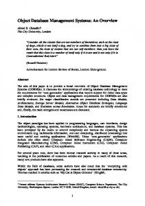
(b) Figure 1. The proposed 3D object recording and reconstruction system. (a) recording system for digital holograms using a phase-shifting interferometer and (b) optical reconstruction system using phase-only information of digital holograms: BS, beamsplitter; BE, beam expander; M, mirror.
2. RECONSTRUCTION USING PHASE-ONLY INFORMATION An illustration of the proposed 3D object recording and reconstruction system is presented in Fig. 1. The proposed system consists of two subsystems; one is a recording system for digital holograms of 3D objects and the other is an optical reconstruction system using phase-only data of a digital hologram. For the recording system, we use a Mach-Zehnder interferometer architecture as a phase-shifting interferometer. A laser beam is divided into two beams by beamsplitter BS1. A 3D object is illuminated by one collimated laser beam (the object beam) and it diffracts this beam. The diffraction pattern propagates to a CCD camera that is located at a distance z along the optical axis and is described by e (x0 , y 0 ) = A(x0 , y 0 ) exp[iϕ(x0 , y 0 )] U ½ ¾ ZZZ ¤ ik £ 0 1 1 2 0 2 (x − x) + (y − y) dxdydz , = U (x, y, z) exp(ikz) exp iλ z 2z
(1)
where l and k are the wavelength and the wavenumber of the illumination, respectively. In Eq. (1), A(x 0 , y 0 ) and ϕ(x0 , y 0 ) are, respectively, the amplitude and the phase of the complex optical electric field at the CCD plane. The diffracted beam interferes in line with a reflected plane wave (the reference beam) using beamsplitter BS2. To permit the reconstruction of the complex field of the 3D object, as described by Eq. (1), from a digital
hologram we employ a phase-shifting digital holography technique8 to capture the hologram. This technique is effective in removing the conjugate reconstruction even when an in-line hologram is used. To implement phase-shifting digital holography, the reference beam passes through both a half-wave plate and a quarterwave plate as shown in Fig. 1(a). Phase retardations in the reference beam of 0, π/2, π, and 3π/2 can be achieved by controlling the positions of the fast and slow axes of the two plates. Using the resulting four digital interferograms, the complex field of the 3D object in Eq. (1) can be calculated as described in Refs. 8 and 9. It has already been shown that with computer reconstruction the fully complex field of the 3D object calculated from the digital holograms can be successfully reconstructed. Using the complex field of the hologram, we can reconstruct numerically the 3D object by the Fresnel-Kirchhoff integral, written by ¾ ½ ZZ ¤ ik £ 1 0 0 1 0 2 0 2 e dx0 dy 0 . (2) U (x , y ) exp(−ikz) exp − (x − x ) + (y − y ) R(x, y; z) = − iλ z 2z
In the proposed method that uses phase-only information, a reconstructed object is described as ½ ¾ ZZ ¤ a 1 ik £ P (x, y; z) = − exp[iϕ(x0 , y 0 )] exp(−ikz) exp − (x − x0 )2 + (y − y 0 )2 dx0 dy 0 , iλ z 2z where
a=
s RR RR
(3)
2
|R(x, y; z)| dxdy 2
|P (x, y; z)| dxdy
.
(4)
Note that the total powers of Eqs. (2) and (3) have been made equivalent by choosing a as indicated in Eq. (4). In the next section we evaluate the quality of the reconstructed 3D object using phase-only information.
3. NUMERICAL EVALUATION To evaluate the error in the reconstructed 3D object, we calculate a normalized root mean square (NRMS) criterion as follows, r ³ ´2 RR 2 2 |R(x, y; z)| − |P (x, y; z)| dxdy r ³ (5) NRMS = ´2 RR 2 |R(x, y; z)| dxdy
In Eq. (5), the error is normalized by the total power of the 3D object. Note that the total powers in R and P can be made equivalent by adjusting a in Eq. (4).
Digital holograms of 3D objects are recorded optically as shown in Fig. 1(a). Numerically reconstructed 3D objects are evaluated. An argon ion laser operated at a wavelength of 514.5 nm is used for the recording beams. The CCD array consists of 2028 × 2044 pixels. Each pixel is 9 µm × 9 µm and has 1024 gray levels (10 bits). We use two 3D objects in the experiments: one is a die with dimensions 5 mm × 5 mm × 5 mm and the other is a screw of similar size. The die and the screw are located at distances of 322 mm and 390 mm from the CCD, respectively. Figures 2(a) and (b) show the numerically reconstructed 3D die object using fully complex information and phase-only information, respectively. Figures 3(a) and (b) show the numerically reconstructed 3D screw object using fully complex information and phase-only information, respectively. These figures show that the phase-only information can reconstruct the 3D object successfully. We can also see that speckle noise is an influence on both 3D reconstructed images. We evaluate the reconstructed 3D object. The speckle noise makes the evaluation of the reconstructed 3D object difficult because speckle noise is very sensitive to phase error. The reconstructed 3D objects are low-pass filtered by a mean filter to reduce the speckle noise in the reconstructed image. The low-pass filtered images are presented in Figs. 2(c), 2(d), 3(c), and 3(d). The sizes of the mean filter in Figs. 2(c) and 3(c) are 11 × 11 pixels,
(a)
(b)
(c)
(d)
Figure 2. Numerically reconstructed 3D objects of the die from (a) fully complex field, (b) phase-only information, (c) low-pass filtered 3D objects with a mean filter of 11 × 11 pixels and (d) 21 × 21 pixels after reconstruction using phase-only information.
(a)
(b)
(c)
(d)
Figure 3. Numerically reconstructed 3D objects of the screw from (a) fully complex field, (b) phase-only information, (c) low-pass filtered 3D objects with a mean filter of 11 × 11 pixels and (d) 21 × 21 pixels after reconstruction using phase-only information.
0.4
Normalized RMS difference Normalized RMS difference
Die Screw 0.35
0.3
0.25
0.2
0.15
0.1
5
10
15
20
25
30
Side length ofofmean filter filter Side length mean
Figure 4. NRMS difference between reconstructed 3D objects from fully complex field and reconstructions from phaseonly information as a function of side length of mean filter.
and in Figs. 2(d) and 3(d) are 21 × 21 pixels. The intensity levels are scaled to enhance the contrast. We can see that speckle noise is removed to a large extent by low-pass filtering. The intensities of the die and the screw reconstructed from the phase-only holograms are compared with the intensities of the objects reconstructed from fully complex holograms, for different mean filtering neighborhoods. Figure 4 shows normalized NRMS difference as a function of the side length of the mean filter. We can see that the NRMS difference is reduced as the size of mean filter increases for both 3D objects. In the die 3D object, the error is reduced from 40% to 15%. Since the screw has more detailed information than the die, the effect of the speckle noise in the screw reconstructions is stronger than in those of the die. We believe that the remaining error is due to the remaining speckle noise.
4. OPTICAL RECONSTRUCTION The optical setup to reconstruct 3D objects is shown in Fig. 1(b). A He-Ne laser operating at a wavelength of 632.8 nm is used. After the collimation and the beam-width expansion of the He-Ne laser beam, the beam illuminates a liquid crystal SLM with 1024 × 768 pixels. The size of each pixel is approximately 18 µm × 18 µm. This SLM does not have enough pixels to display the complete 2044 × 2028 pixel phase-only hologram, and so a 1024 × 768 pixel window is presented. By measuring phase retardation of the SLM in a Mach-Zehnder interferometer, the maximum amount of phase retardation possible with our SLM is 0.6π. The phase retardation is almost linearly proportional to the signal level from the computer. Figures 5 and 6 show the reconstructed 3D die and screw objects. Figures 5(a), (b) and (c) contain reconstructions with the CCD located at distances of 113 mm, 123 mm, and 133 mm from the SLM, respectively. Figures 6(a), (b) and (c) show reconstructions at distances of 135 mm, 155 mm, and 165 mm from the SLM, respectively. Figures 5(b) and 6(b) are the most in focus. From these figures we can see that the die and the screw are reconstructed at different planes. The calculated positions of the in-focus reconstructions are 104 mm and 126 mm, respectively. These errors are caused by the small amount of phase retardation possible with our SLM, our use of a different readout wavelength, different pixel size, and a readout wavefront not exactly the same as a plane wave.
5. CONCLUSIONS We have proposed a method to reconstruct 3D objects that uses only the phase information of the complex field from digital holograms. Experimental demonstration shows that the optical reconstruction of views of 3D
(a)
(b)
(c)
Figure 5. Experimental results; (a), (b) and (c) are reconstructed images of the die where the CCD is located at 113 mm, 123 mm, and 133 mm from the SLM, respectively.
(a)
(b)
(c)
Figure 6. Experimental results; (a), (b) and (c) are reconstructed images of the screw where the CCD is located at 135 mm, 155 mm, and 165 mm from the SLM, respectively.
objects can be implemented successfully. Numerical evaluation shows that NRMS errors of from 10% to 40% appear due to speckle noise. These errors were caused by the loss of amplitude information in the hologram. It is possible that the error could be decreased by manipulation of the hologram’s phase distribution. We think that the proposed method is a promising way for a real-time 3D display because the phase-only reconstruction allows us to use commercially available display devices such as liquid crystal SLMs.
REFERENCES 1. J. W. Goodman, Introduction to Fourier Optics, McGraw-Hill, New York, second ed., 1996. 2. H. J. Caulfield, ed., Handbook of Optical Holography, Academic Press, New York, 1979. 3. F. Okano, J. Arai, H. Hoshino, and I. Yuyama, “Three-dimensional video system based on integral photography,” Opt. Eng. 38, pp. 1072–1077, 1999. 4. A. D. McAulay, Optical Computer Architectures: The Application of Optical Concepts to Next Generation Computers, Wiley, New York, 1991. 5. N. Yoshikawa and T. Yatagai, “Fringe pattern correlator for three-dimensional object recognition,” Opt. Lett. 25, pp. 1424–1426, 2000. 6. B. Javidi and F. Okano, eds., Three Dimensional Television, Video, and Display Technologies, Springer, Berlin, 2002. 7. U. Schnars and W. Juptner, “Direct recording of holograms by a CCD target and numerical reconstruction,” Appl. Opt. 33, pp. 179–181, 1994. 8. I. Yamaguchi and T. Zhang, “Phase-shifting digital holography,” Opt. Lett. 22, pp. 1268–1270, 1997.
9. B. Javidi and E. Tajahuerce, “Three-dimensional object recognition by use of digital holography,” Opt. Lett. 25, pp. 610–612, 2000. 10. M. Sutkowski and M. Kujawinska, “Application of liquid crystal (LC) devices for optoelectronic reconstruction of digitally stored holograms,” Optics and Lasers in Engineering 33, pp. 191–201, 2000. 11. E. Tajahuerce, O. Matoba, and B. Javidi, “Shift-invariant three-dimensional object recognition by means of digital holography,” Appl. Opt. 40, pp. 3877–3886, 2001. 12. Y. Frauel, E. Tajahuerce, M.-A. Castro, and B. Javidi, “Distortion-tolerant three-dimensional object recognition with digital holography,” Appl. Opt. 40, pp. 3887–3893, 2001. 13. O. Matoba, T. J. Naughton, Y. Frauel, N. Bertaux, and B. Javidi, “Real-time three-dimensional object reconstruction using a phase-encoded digital hologram,” Appl. Opt., 2002. To appear.