Computer Science & Engineering: An International Journal (CSEIJ), Vol.3, No.1, February 2013
THROUGHPUT/AREA TRADE-OFFS OF LOOPUNROLLING, FUNCTIONAL, AND STRUCTURAL PIPELINE FOR SKEIN HASH FUNCTION George S. Athanasiou1, Elias Tsingkas1, Harris E. Michail2, George Theodoridis1 and Costas E. Goutis1 1
Department of Electrical and Computer Engineering, University of Patras, Greece
[email protected]
2
Department of Electrical Engineering, Computer Engineering and Informatics, Cyprus University of Technology, Limassol, Cyprus
ABSTRACT In this paper, a design space exploration is performed aiming at developing high-performance hardware architectures for the new cryptographic hash function Skein-512. Three well-known design optimization techniques namely, the loop unrolling, the structural and functional pipeline, are applied, while several design alternatives have been explored to derive optimized FPGA implementations. The proposed architectures have been implemented and evaluated in three Xilinx technologies (Virtex-4, Virtex-5, and Virtex-6). Based on the experimental results, when all the three techniques are applied, the best architecture is the 8-round_unroll one with two functional and three structural pipeline stages. To the best of the authors’ knowledge, it is the first time that all these three techniques are studied and exploited together for the Skein algorithm. Also, the proposed architectures outperform the corresponding existing ones in terms of Throughput/Area factor from 27% up to 192%, respectively.
KEYWORDS Security, Authentication, Hash functions, Skein, FPGA
1. INTRODUCTION 21st century is considered to be the era of mass communication and electronic information exchange. However, this advancement goes in parallel with serious considerations regarding the security of the exchanged information, especially when this information is sensitive and/or confidential. To overcome this problem, advanced security mechanisms are included in modern communication protocols as well as in data transmission and communication systems. Typical examples are the encryption and authentication which are performed in every transmitted data packet by the forthcoming Internet Protocol version 6 (IPv6) [1] via the Internet Protocol Security (IPSec) [2]. Regarding authentication, which is an important feature of IPSec, it is realized using a standard hash algorithm [3]. Beyond that, hash functions are among the crucial building blocks of many popular security systems and applications like Secure Electronic Transactions (SET) [4], IEEE 802.16 standard [5] for Local and Metropolitan Networks, digital signature schemes [6] and web protocols [7]. Skein [10], [17] is a new cryptographic hash function, introduced in the end of 2010. It combines speed, security, simplicity, and a great deal of flexibility in a modular package that is easy to DOI : 10.5121/cseij.2013.3101
1
Computer Science & Engineering: An International Journal (CSEIJ), Vol.3, No.1, February 2013
analyze. In fact, it was one of the five finalists of the international hash function competition, launched by NIST [10]. It is well-known that the computational complexity of security algorithms often becomes the host system’s bottleneck [11], [44]. This becomes more pronounced when hard real-time constraints must be satisfied or high-speed communication networks (e.g. optical networks) are used. In the last case, a large amount of the available bandwidth may not be utilized if the employed systems are characterized by low throughput processing [43]. To overcome these bottlenecks, highthroughput architectures are demanded, which is mainly achieved by implementing the security algorithms in hardware [11, 12, 13]. Regarding Skein hash function, there are few software implementations in the literature, such as [17-20]. Regarding the hardware implementations of Skein, the works presented in literature can be classified in two main categories. The first category includes the works that perform comparative studies among the candidates of NIST’s hash competition [24-41]. The main goal of these works is not to develop sophisticated architectures but to study the performance of these algorithms when they are implemented in hardware. For that reason, different architectures for each algorithm are proposed applying general design techniques (e.g. pipeline). Then, the introduced architectures are implemented in hardware using mainly FPGA technologies and they are compared in terms of area, frequency, and throughput. The second category includes the works which target at developing advanced hardware architecture for the Skein algorithm only. The main goal of these works is the development of architectures characterized by high throughput and low area. In [21] the loop unrolling technique was applied in order to improve delay and throughput. In [22], novel architectures for all the three types of Skein algorithm (256, 512, and 1024) were proposed using an 8-round unrolled data-path. Walker et al. in [23] proposed 4 different architectures depending on the number of pipeline stages, namely zero, two, four and eight, employing the 8-round unrolled data-path. Finally, in [42], a low-area coprocessor for the internal structure of Skein, named Threefish, is designed, exploiting interleaving and parallelism. In this paper, a design space exploration is performed aiming at developing hardware architectures for the Skein-512 algorithm characterized by high performance in terms of Throughput/Area metric. Three design optimization techniques namely, the loop unrolling, the structural, and functional pipeline are studied and 10 different architectures, which vary in the number of the applied loop unrolling depth and pipeline stages, are proposed. These architectures are categorized in three sets. The first set includes the architectures which are produced by applying the loop unrolling technique, the second set corresponds to the architectures which are derived by utilizing the loop unrolling and structural pipeline, while the last one includes the architectures which are produced by applying both the three above techniques. To the best of the authors’ knowledge, it is the first time that all these three techniques are used to develop hardware architectures for the Skein algorithm. Moreover, all the introduced architectures have been developed to be used either as simple hash modules on MAC ones. Also, special effort has been paid and different design alternatives have been explored to derive optimized FPGA implementations. The proposed architectures have been implemented in three Xilinx technologies (Virtex-4, Virtex-5, and Virtex-6) and evaluated in terms of Throughput/Area. Based on the experimental results, when only loop unrolling is applied, the architecture with unrolling depth equal to 8 (8-round_unroll) is the best, while when loop unrolling and functional pipeline are used together the 8-round_unroll architecture with two pipeline stages outperform the corresponding ones. Finally, when all the three techniques are used, the best architecture is the 8-round_unroll one with two functional and three structural pipeline stages. Moreover, the proposed architectures outperform the existing ones in terms of Throughput/Area, from 27% up to 151%, and from 43% up to 192%, respectively. 2
Computer Science & Engineering: An International Journal (CSEIJ), Vol.3, No.1, February 2013
The rest of the paper is organized as follows. In Section 2 the Skein algorithm is described. In Section 3 the design space exploration is analyzed and the proposed architectures are presented in details. The experimental results and comparisons with similar existing architectures are provided in Section 4. Finally, Section 5 concludes the paper.
2. THE SKEIN HASH FAMILY Skein is a family of hash algorithms with three different internal state sizes: 256, 512, and 1024 bits. Skein-512 is the primary algorithm of the family and can be used for all current hashing applications of modern security systems. Skein-1024 has the same characteristics as Skein-512 but its internal size is twice than the Skein-512. Finally, Skein-256 is the low-memory variant of the algorithm but offers less security than the above two. Skein-512 is considered to be the best choice for drop-in replacement of the existing SHA-family functions in security systems [17]. The basic concept of Skein algorithm is to build a hash function out of a tweakable block cipher. The use of a tweakable block cipher allows the hashing of configuration data along with the input text in every block, making every instance of the compression (hash) function unique. This property directly addresses many attacks on hash functions and greatly improves Skein's flexibility [17]. Specifically, Skein is built by the following three components: (a)Threefish: it is a tweakable block cipher at the core of Skein algorithm, (b)Unique Block Iteration (UBI): it is a chaining mode that uses Threefish to build a compression function that maps an arbitrary input size to a fixed output size, and (c)Optional Argument System (OAS): it is a set of optional features that are supported by Skein, without imposing any overhead on implementations that do not use them. In the following sub-Sections, the main components (Threefish and UBI) of Skein algorithm are presented. More details for Skein hash function can be found in [17].
2.1. Threefish Component Threefish, is used in Matyas-Meyer-Oseas mode to construct the Skein compression function [17]. During the Threefish process, the N-bit plaintext is portioned in w=N/64 64-bit words. These words are grouped in pairs of two, let (W0, W1), for each round and serve as input in a MIX function, which is described by the following equation: MIX [W0 ,W1 ] = W0 + W1 , (W1
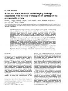
Figure 1. 1-round unrolled Skein-512 Hash/MAC Architecture 5
Computer Science & Engineering: An International Journal (CSEIJ), Vol.3, No.1, February 2013
The architecture is able to operate either as Hash or MAC module depending on the user’s choice. For that reason, the sel_mac signal is used to determine the type of operation (Hash or MAC). Concerning the input message, this is fed in through the msg input in 64-bit words, while the 7-bit length input denotes the number of the bits of the last active data of the input message. Also, the signals new_msg and last_block are active when a new message exists and the last message block is inserted, respectively. The architecture outputs the hash value in 64-bit words through the md output, whereas the valid signal is set to high level during this procedure. To perform a complete Skein operation, 73 clock cycles are demanded. Specifically, 72 clock cycles are needed to execute the 72 rounds of Threefish-512 components, whereas one more cycle is spent for the computation of the first sub-key. More details, on the required clock cycles are given in the presentation of the control unit. The Input Block component contains the Padding unit, which is responsible to form the 512-bit input block for the hash computation and the Starting Signal Production unit, which produces four signals. The three of them (first, final, position) are used as input in the Teak Generator for the production of the teak values, while the forth signal (start_keygen) is fed in the Control Unit in order to start the computation of the sub-keys. The Control Unit itself sends two synchronization signals (start_counter, rst_inp) to the Input Block to start a new padding. The Tweak Generator component is responsible for producing the appropriate teak values for each operation mode [17]. It uses the first, final, pad (non-zero when padding was performed in Input Block) bits, along with the 96-bit position quantity that indicates the number of message bytes that have already been processed, and forms the teak value through concatenation (as imposed by the standard [17]). The main part of the computations is performed by the Rounds component, which is illustrated in Figure 2. Its organization is based on the MIX-permute pairing structure of the algorithm. In particular, it consists of four MIX and one permutation module, while eight 64-bit adders are also included for adding the sub-keys. Regarding the MIX and Permute modules, they have been designed as described in the algorithm’s specifications (Section 2 and [17]). Due to the fact that every four rounds a different sub-key is added, there is a 512-bit 2to1 multiplexer before the MIX modules. Moreover, as it shown in Figure 1, just before the Rounds component, there is a 4to1 multiplexer that is responsible of feeding it with the appropriate input. If a configuration UBI has to take place, then the input of the Rounds is the predetermined input for it, as described by the algorithm, while if an output UBI is to begin, then the input is set to “0”. To start the hash computation of a new message, the output of the Input Block is chosen, while if a multi-block message is processed, the multiplexer feeds back the 512-bit output.
Figure 2. The Rounds component 6
Computer Science & Engineering: An International Journal (CSEIJ), Vol.3, No.1, February 2013
The required sub-keys are produced by the Key Generator component, the block diagram of which is shown in Figure 3(a). This component implements the key computation equations, which has been presented in Eq.3 of Section 2. However, instead of using simple registers for storing the intermediate values of the sub-keys and tweaks, two shift registers are used so as to fully exploit the cyclic process of the key/tweak production that the algorithm imposes (circles 1 and 2). It also contains XOR gates, three 64-bit adders, and two concatenation modules (circuitry in cycle 3). Also, as it is shown in Figure 1, an additional 512-bit 3to1 multiplexer, whose output is fed to the Key Generator component, is included in the architecture. It is controlled by the Control Unit and feeds the Key Generator component with the appropriate values based on the architecture’s operation mode. Specifically, if the calculation of the first sub-key takes place (the process of the first 512-bit bloc has not started yet), then the “0” value is set, whereas if the Configuration UBI process is to be performed, then the predetermined configuration value is set. In any other case the current Threefish output is set as input and used as key for the next Threefish.
> >
>
Figure 3. (a)The Key Generation component, (b) The FSM’s state diagram
Concerning the Control Unit, it has been implemented as a Finite State Machine (FSM) including also a counter to control the Rounds component. The FSM, which is illustrated in Figure 3(b), has five states, namely the: Idle, Key, Config, Message, and Output. The system’s initial is the Idle in which the system remains until a new message block arrives (new_msg=1). Then, based on the value of the sel_mac signal, it starts the production either of the key (when it is in MAC mode sel_mac=1) or the hash computation (hash mode - sel_mac=0). As far as MAC operations mode concerns, the key UBI is accomplished after 73 × key _ length clock cycles (where key_lenght is
512
the desired length of the key, in bits). Afterwards, the system flips to Config (Configuration UBI) where it remains for 73 cycles. Then it flips to Message state, where the main hash computation takes place. The system remains there for 73 × message _ length cycles (where message_length is
512
the length of the message in bits). The last state is the Output (Output UBI) where the system remains for 73 cycles before pops out the result, when in MAC mode. If there is another message for processing, the system goes back to Message. In other case, it flips to Idle. Regarding the hash 7
Computer Science & Engineering: An International Journal (CSEIJ), Vol.3, No.1, February 2013
mode, the computation, after the Idle state, continues to Message and then to Output, similarly to above. The Control Unit’s circuitry contains a counter and simple logic modules, such as logic gates, flip-flops etc. Additionally to the above control component, there is a smaller counter that counts up to 8 inside the Input Block component. This small counter is responsible for the appropriate synchronization of the padding procedure with the rest of the architecture and the indicating that new data can be inserted for padding. 3.1.2. 4-round Unrolled Architecture Regarding the 4-round unrolled architecture (4-round_unroll), there are few differences compared to the 1-round unrolled one, mainly concerning the organization of the Rounds and Control Unit. The other components have negligible, logic-level, differences. In particular, in the Rounds component, 4 MIX-permute pairs are sequentially connected resulting in 16 MIX and 4 Permute modules. Also, there are eight 64-bit adders for the subkeys. Due to the fact that every four rounds a different subkey is added, there is a 2to1 multiplexer before the MIXes. Concerning the Control Unit, it is similar to the one presented in Figure 3(b). However, to correctly control the current architecture, the internal counter counts up to 17. Thus, the Config_1, Message_2, and Output_1 states iterate (when desired) 17 times. The rest functionality of the Control Unit is the same as described in 3.1.1. 3.1.3. 8-round Unrolled Architecture As in 4-round unrolled architecture, the differences between the 8-round (8-round_unroll) and the 1-round unrolled architectures, mainly concern the Rounds and the Control Unit. Regarding the Rounds component, there are 32 MIX and 8 Permute modules in total. Additionally, due to the applied eight times loop unrolling, the Rounds component has two separate inputs for sub-keys. Also, just before the Rounds component, there is a 4to1 multiplexer that is responsible of feeding it with the appropriate input. Furthermore, due to the 8-round unrolling and the fact that a sub-key is need every 4 rounds, the Key Generator produces two sub-keys at the same time. The block diagram of this Key Generator is similar to one of Figure 3(a), however it has some modifications. Instead of simple registers for storing the intermediate values of the sub-keys and tweaks, two shift registers are used again, to fully exploit the cyclic process of the keys and tweaks that the algorithm imposes (Section 2 and [17]). However, it contains twice the circuitry of circle 3 in Figure3 (a) (6 64-bit adders and 4 concatenation modules) so as to feed the Rounds component with two sub-keys per clock cycle. Concerning the Control Unit, is similar to the one presented in Figure 3(b), however, to correct control the current architecture, the internal counter counts up to 8. Thus, the Config_1, Message_2, and Output_1 states iterate (when desired) 8 times. The rest functionality of the s is the same as described in 3.1.1).
3.2. Pipeline Exploration As it is known, a widely-used method to improve throughput is pipeline. This is accomplished splitting the critical path in shorter ones by inserting registers in proper positions creating pipeline stages, which are located between the pipeline registers. In that way, after a latency delay, different input data are processed concurrently in the pipeline stages resulting in significant throughput improvement. However, the use of the pipeline registers results in area increase, while the control unit also becomes more complex. Moreover, after a certain point, the increase of the 8
Computer Science & Engineering: An International Journal (CSEIJ), Vol.3, No.1, February 2013
number of pipeline stages results in negligible throughput improvements. Hence, in order to develop an architecture characterized by high Throughput/Area values, a careful study is demanded to determine the number and position of the pipeline stages. 3.2.1. Functional Pipeline Concerning the Skein algorithm, a way of applying the pipeline technique is the insertion of pipeline registers inside the Round component and specifically between the consecutive executed rounds. This kind of pipeline is denoted as Functional Pipeline. As it will be reported and discussed in the experimental results (Section 4.1), the 8-round unroll architecture is the best in terms of Throughput/Area factor. Thus, it is considered as the base architecture on which the functional pipeline is applied. Due to the 8 times loop unfolding, the Round component executes 8 iterations together. Thus, as the aim is the insertion of pipeline registers between the consecutive rounds without causing significant synchronization overheads, three design alternatives exist. These are the 2, 4, and 8-staged pipelined architectures. A general block diagram of a p-stage (p =2, 4, 8) pipelined architecture is shown in Figure 4. Comparing this architecture to that of Figure 1, they differ in three points. First, in the Rounds component, there are 8/p MIX-Permute pairs followed by a pipeline register. The triplet (MIXpermute) - Register - (MIX-Permute) is repeated p/2 times before and after the 8 64-bit adders that are located in the middle. Additionally, there are p registers on the left of Rounds component for the correct synchronization of the appropriate input block that is to be XORed with the corresponding output. Also, for synchronization reasons, there are (p-1) additional registers at the XORs output that is fed in the 3to1 multiplexer that feeds the Key Generators.
>
> > >
>
>
>
>
>
Figure 4. N-staged pipelined architecture based on the 8-round unrolled Skein-512 one
9
Computer Science & Engineering: An International Journal (CSEIJ), Vol.3, No.1, February 2013
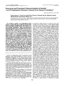
In order to support the Rounds component with the required sub-keys, the Key Generator component has to be modified as well. The straightforward choice would be the incorporation of p Key Generator components, each one responsible for the corresponding message block that is processed in each one of the p stages. However, this would lead to significant increase of the occupied area. To overcome this issue without increasing the critical path, which is located inside the Rounds component, a different approach was followed. Specifically, two Key Generator components were designed (Key Generator 0 and Key Generator 1). Each one includes p/2 shift registers (same as those inside circles 1 and 2 of Figure 3(a)), which are responsible for producing the appropriate sub-key and tweak values for the corresponding message block. In every clock cycle, one key shift-register-tweak shift-register pair will operate, supporting the corresponding message block that is processed. This way, there are only three adders and two concatenation modules (same circuitry as in circle 3 of Figure 3(a)) that are shared among the shift-registers, leading to significant area decrease compared to the straightforward choice. To correctly control the above procedure and selecting the working shift-register, additional steering logic is used consisting of two p/2_to_1 multiplexers before the above circuitry. Regarding the Control Unit it is also developed as hardwired FSM and it is similar to that of Figure 3(b). However, it is larger as additional control signals must be produced. Also it contains a counter that counts up to a number which depends on the number of the employed pipeline stages p. To compute a hash value of a 512-bit message block, the Round component iterates 72/8 = 9 times (due to the 8-round unrolling), but now its iteration last p clock cycles. An additional clock cycle for producing the first sub-key is required (similarly to the designs with no pipeline of sub-Section 4.1), as well as one more for synchronization purposes of the last pipeline stage with the rest ones. Hence, the total clock cycles of the above designs functionality, regarding the hash processing of a message block, are: (9 × p) + 2, and specifically 20, 38, and 74 clock cycles for 2, 4, and 8-staged pipelined designs, respectively. 3.2.2. Structural Pipeline Another pipeline topology that could be considered for the Skein algorithm is the structural one. This is accomplished by repeating consecutively modules of Threefish module, which operate on data of different message blocks independently from one to another. Taking into account that the 8-round unrolled module is the best choice for the Threefish module, a structural pipelined architecture considering three of the above modules is constructed, as illustrated in Figure 5. As it is shown, there are three independent 8-round unrolled Threefish modules (Round) consecutively connected. Each one of them performs three iterations, so as the design to perform (3 × 8) × 3 = 72. Regarding the Key Generator component, it is split to three different ones, which are the Key Generator 1, 2, and 3. Each one of them is responsible to feed the corresponding Round component with the required sub-keys. Concerning their internal organization, the Key Generator 1 is similar to the one shown in Figure 4, with an additional output for feeding the Key Generator 2 with the appropriate sub-keys and tweaks for its computation, through parallel loading of its shift registers. Key Generator 2 is similar to Key Generator 1 without the XOR trees before the shift registers (see Figure 3(a)). Finally, the Key Generator 3 is similar to Key Generator 2 without the output for parallel loading. As discussed in sub-Section 3.1.3, the 8-round unrolled architecture requires one extra clock cycle for the computation of the first sub-key. Hence, in the 3-staged structural pipelined architecture three additional clock cycles would be required. To avoid the delay of these cycles, there is an additional one (Key Generation 0) just before the first Round component, which is responsible for the computation of the first sub-key. This component is much simpler than the 10
Computer Science & Engineering: An International Journal (CSEIJ), Vol.3, No.1, February 2013
other key generators. As imposed by the algorithm, for the computation of the first subkey, the K8 and t2 values are not required. Thus, the corresponding XOR trees of Figure 3(a) are omitted. Additionally, as only one subkey is produced, there is no need for shiftregisters and extra addition with the subkey’s order number (Figure 3(a)). Hence, this block consists of only two 64-bit adders (key+tweak) and a concatenation that forms the final skey. Finally, similarly to Figure1, there is a multiplexer in front of each Round, so as to feed it with the appropriate input (feed-back the current output or the output of the previous Round).
> >
>
>
>
>
>
Figure 5. 3-staged structural pipelined architecture based on the 8-round unrolled Skein-512
The Control Unit of the pipelined designs consists, once again, of an FSM. However, it is larger, and is split to 4 sub-components. The FSM, as well as the main circuitry of the unit is included in 11
Computer Science & Engineering: An International Journal (CSEIJ), Vol.3, No.1, February 2013
the Control Unit 1/2, while the rest is included in the Control Unit 2/2. The latter consists of three counters, each one of them counting up to and producing the additional control signals, required by its corresponding Round and Key Generator. 3.2.3. Combination of Functional and Structural Pipeline The two pipeline styles (functional and structural) can be combined leading to more effective designs in terms of throughput. However, this results in important area overhead. Hence, an exploration is required in order to develop an architecture characterized by improved Throughput/Area values. To accomplish this exploration, three more architectures were developed, which incorporated 2, 4, and 8 stages of functional pipelining inside the Rounds component. Regarding the rest components (e.g. Key Generators, Control Unit(s), etc), a combination of the above topologies was accomplished. For clarity reasons, as well as to avoid increased length of the manuscript, the block diagrams of these architectures are not presented.
4. EXPERIMENTAL RESULTS AND COMPARISONS The above-introduced architectures were captured in VHDL, synthesized, and implemented in FPGA technology using the Xilinx ISE Design Suite v.13.1. Also, for the implementation of the architectures, the Virtex-4 (xc4vlx160-FF1148) and Virtex-5 (xc5vfx130t-FF1738), and Virtex-6 (xc6vlx365t-FF1759) FPGA families were selected. The correct functionality of the architectures was initially verified through Post-Place and Route (Post-P&R) simulations using the ModelSim simulator. Thereafter, downloading to FPGA boards was performed and the functionality of each implementation was verified on the board using the Xilinx ChipScope tool. The comparisons among all the proposed architectures are accomplished in terms Delay, Throughput, Area, and Throughput/Area cost factor. Similarly to previous works dealing with hardware implementations of Skein hash family, Throughput is calculated by Eq. 4: Throughput =
( # bits ) × f c
(4)
where f and c correspond to the frequency and the consumed clock cycles, while #bits denotes the data bits that are processed in each cycle. The total number of clock cycles includes the cycles consumed to input data, to execute hashing process in the core function block, to perform the final calculation process and to output the hash results. However, when the hashing concerns long messages (which is the real world case), given the fact that the Throughput, in most of the cases, is the maximum sustainable throughput for a given frequency, the potential cycles for inserting data, performing the final calculation process and popping out the hash result are negligible and ignored. In the following sections the experimental results are presented and discussed. Firstly, we present the performance results of the proposed architectures and we discuss and evaluate the application of the applied optimization techniques (loop unrolling, functional, and structural pipeline). Then, comparisons between the introduced and existing works are presented.
4.1. Loop-Unrolling Evaluation As stated above, the critical path of all the three architectures is located inside the Rounds component. In particular, the 1-round_unrolled architecture presents the smallest critical path (one MIX-permute pair, one 64-bit adder, one 512-bit 2to1 multiplexer, and one 512-bit 4to1 12
Computer Science & Engineering: An International Journal (CSEIJ), Vol.3, No.1, February 2013
multiplexer). Moreover, it occupies the least area among the three architectures. Consequently, as the unrolling factor increases from one to four and then to 8, the occupied area increases and the critical path gets longer. Additionally, due to the unrolling application, the c variable in Eq. 4 is rather smaller in 4-round_unrolled and 8-round_unrolled architectures (19 and 10 respectively) compared to the corresponding one of 1-round_unrolled architecture (73). However, the behaviour of the Throughput metric, as the unrolling factor increases cannot be fully theoretically determined. Figure 6 shows the experimental results for the proposed loop unrolled architectures. As it was expected the 1-round_unroll architecture (i.e. without performing loop unrolling) exhibits the smallest delay and occupied area, whereas as the value of the unrolling factor increase both delay and area also increase. However, the increase of area and delay is not linear to the unrolling factor. This happens due to the following reasons. Concerning area, as it known each FPGA slice contains one or more LUTs, multiplexers, and flip-flops (F/Fs) to implement logic. Thus, as the number of the unrolling factor increases and the design becomes more complex, better exploitation of the slice’s resources takes place, which results in a non-linear area increase. In more details, comparing the 8-round_unroll architecture with the 4-round and 1-round unroll ones in Virtex-6 technology, the area increases by 9% and 33%, respectively. Similar results stand for the Virtex-4 and Virtex-5 implementations. FPGA Family
Virtex-4
Virtex-5
Virtex-6
1-round_unroll
Frequency (MHz) 171.4
Area (Slices) 3142
Throughput (Mbps) 1202.2
4-round_unroll
113.2
3756
3049.1
8-round_unroll
77.3
4616
3957.8
1-round_unroll
212.9
1226
1493.4
4-round_unroll
148.1
1508
3990.4
8-round_unroll
99.4
1841
5089.3
1-round_unroll
280.9
1229
1970.1
4-round_unroll
181.2
1494
4882.9
8-round_unroll
118.3
1629
6057.0
Architecture
Figure 6. Loop unrolled architectures: (a) Frequency, area, throughput, (b) Throughput/Area
Regarding the achieved frequency, the architectures’ organization must be taken into account. Specifically, in the Rounds component of the 4-round-unrolled architecture there is not any internal steering logic of the input block controlled by the appropriate sub-keys; in contrast, in case of 1-round-unrolled architecture, there is a 2to1 512-bit multiplexer. Also, the 4-round unfolding operation corresponds to the placement of 4 MIX-permute pairs consecutively. Hence, the 4to1 512-bit multiplexer, which is placed before the Rounds component and included in the critical path, is not repeated 4 times. Additionally, the internal 64-bit adders and XOR gates are not repeated. Finally, due to the incorporation of more MIX-permute pairs inside the Rounds component of the 4-round-unrolled architecture, more compact placement is achieved by the synthesis tool, which decreases the net delay. Due to the above reasons, comparing the 1-roundunrolled and the 4-round-unrolled architectures, the decrement of the frequency is not quite close to the theoretical one (4x lower). Specifically, in Virtex-6 technology, the frequency of the 8round unroll architecture is lower by 35% and 58% compared to frequency of the 4- and 1-round unroll architectures, respectively. Similar results stand for Virtex-4 and Virtex-5.
13
Computer Science & Engineering: An International Journal (CSEIJ), Vol.3, No.1, February 2013
Studying the achieved throughput it is clear that it is improved with the increase of the unrolling factor and the best architecture in terms of throughput in all technologies is the 8-round unrolled one. As it has been explained in Section 3, 8 iterations of the algorithm are executed in each clock cycle, which results in a drastic decrease of the clock cycles. In Virtex-6, the throughput of the 8round unroll architecture is improved by 24% and 207% compared to the throughput of the 4- and 1-round unroll architectures, respectively. The corresponding improvements in Virtex-5 technology are 28% and 241%, whereas in Virtex-4 they are 30% and 229%. To perform a more accurate and fair evaluation of the proposed architectures, the Throughput/Area metric is studied. As it shown in Figure 6(b), the Throughput/Area factor is improved when the unrolling factor increases. Specifically, comparing the 8-round unrolled architecture with the 4-round and 1-round unrolled ones in Virtex-6 technology, the Throughput/Area factor is improved by 14% and 133%, respectively. Similar results also hold for the Virtex-4 and Virtex-5 implementations. Finally, the 8-round unroll architecture achieves the higher Throughput/Area value among all the implementations of all architectures in all technologies. For that reason, this architecture was selected as the base one to apply the functional and structural pipeline techniques.
4.2. Functional Pipeline Evaluation In Figure 7 the experimental results of the pipelined architectures are presented. Four pipelined architectures are studied, which are the 8r_nFp, 8r_2Fp, 8r_4Fp, and 8r_8Fp with none, two, four, and eight pipeline stages, respectively. For the reason explained above, the 8-round unroll one was used as the base architecture in which pipeline was applied. As expected, the frequency, area, and throughput increase as the number of the stages increases. Also, the above metrics are improved when the modern Virtex-6 FPGA technology is used. Specifically, in Virtex-6, the frequency improvements of the 8r_2Fp, 8r_4Fp, and 8r_8Fp architectures over the 8r_nFp one are 75%, 109%, and 125%, respectively. Also, comparing the 8r_nFp design with the 8r_2Fp, 8r_4Fp, and 8r_8Fp ones, the throughput improvements are 75%, 109%, and 125%, whereas the area increases by 36%, 98%, and 162%, respectively. Family
Virtex-4
Virtex-5
Virtex-6
Architecture
Frequency (MHz)
8r_nFp 8r_2Fp 8r_4Fp 8r_8Fp 8r_nFp 8r_2Fp 8r_4Fp 8r_8Fp 8r_nFp 8r_2Fp 8r_4Fp 8r_8Fp
77.3 108.5 124.2 133.5 99.4 162.3 191.6 199.3 118.3 206.6 247.0 266.4
Area (Slices) 4616 6133 8465 11369 1841 2675 4082 5506 1629 2212 3219 4272
Throughput (Mbps) 3957.8 5556.2 6359.0 6835.2 5089.3 8309.8 9809.9 10204.2 6057.0 10579.5 12647.9 13639.2
Figure 7. Functional pipelined architectures: (a) Freq., area, throughput, (b) Throughput/Area
It should be mentioned that the frequency improvement is not proportional to the number of the pipeline stages because increasing the pipeline stages the design becomes more complex making difficult the efficient implementation (e.g. placement) of the logic in the FPGA resources. This results in high routing overhead which strongly affects the final delay. Concerning the area 14
Computer Science & Engineering: An International Journal (CSEIJ), Vol.3, No.1, February 2013
increase, it is also exhibits a similar behaviour and the explanation of this is the same as in loop unrolled architectures discussed above. Observing the Throughput/Area metric, the 8r_2Fp architecture exhibits the best performance in all technologies. Moreover, as it is shown in Figure 15(b), the Throughput/Area factor is reduced significantly in all FPGA technologies, when the number of the pipeline stages increases beyond two. Furthermore, comparing the 8-round unrolled (Section 5.1) and 8r_2Fp architectures in terms of Throughput/Area, it derived that the 8r_2Fp architecture outperforms the 8-round unrolled one in all technologies. Specifically, the Throughput/Area factor is improved by 5.9%, 17.4%, and 28.4% in Virtex-4, Virtex-5, and Virtex-6 technologies, respectively. These improvements justify the worth of the application of the functional pipeline and its combination with the loop unrolling technique.
4.3. Mixed (Functional and Structural) Pipeline Evaluation Figure 8 shows the experimental results for the proposed mixed-pipelined architectures where both loop unrolling, functional, and structural pipeline are applied. Specifically, 3 additional structural pipeline stages (3Sp) are applied in each architecture. Again, the frequency, area, and throughput increase with the number of the pipeline stages, while the implementations on the Virtex-6 technology outperform those on the Virtex-5 and Virtex-4 devices. Family
Virtex-4
Virtex-5
Virtex-6
Architecture 8r_nFp_3Sp 8r_2Fp_3Sp 8r_4Fp_3Sp 8r_8Fp_3Sp 8r_nFp_3Sp 8r_2Fp_3Sp 8r_4Fp_3Sp 8r_8Fp_3Sp 8r_nFp_3Sp 8r_2Fp_3Sp 8r_4Fp_3Sp 8r_8Fp_3Sp
Frequency (MHz) 71.3 106.8 122.6 130.2 91.1 154.1 185.5 196.2 110.0 189.6 228.9 237.1
Area (slices) 14563 18064 24839 25301 6798 8525 11646 16832 5229 6789 9025 12043
Throughput (Mbps) 12166.8 18227.2 20923.7 22220.8 15547.7 26299.7 31658.7 33484.8 18764.8 32358.4 39065.6 40465.1
Figure 8. Mixed pipelined architectures: (a) Frequency, area, throughput, (b) Throughput/Area
Comparing these architectures with those where only functional pipeline is applied, it is derived that the throughput of the mixed-pipeline designs is improved drastically. For instance, for the implementations on the Virtex-6 technology, the throughput of the 8r_8Fp_3Sp architecture is improved by 197% compared to the 8r_8Fp architecture. The corresponding improvements of the 8r_nFp_3Sp, 8r_2Fp_3Sp, 8r_4Fp_3Sp architectures are 210%, 206%, and 209%, respectively. However, this improvement comes with a significant area increase. Studying the Throughput/Area ratios (Figure 7(b) and Figure 8(b)), it is derived that the mixed pipelined architecture is slightly better compared to functional pipelined one. However, as it is mentioned previously, in the mixed pipelined architectures the throughput is improved drastically. Thus, these architectures can be used when the time constraints are very hard and the designer can afford the corresponding area increase.
15
Computer Science & Engineering: An International Journal (CSEIJ), Vol.3, No.1, February 2013
4.4. Comparisons with Previous Works As reported in the Introduction, there are many works published in previous years regarding the implementation of Skein algorithm(s) on FPGA technology. In this Section, we compare and discuss these architectures with the corresponding proposed ones. Initially, the comparison among the un-optimized architectures and the proposed 1-round unroll architecture takes place. In these architectures neither loop unrolling nor pipeline is applied. Then, we compare the architectures in which loop unrolling is applied. Finally, the comparison among the architectures in which loop unrolling and (or) functional pipeline are applied takes place. In the following tables the mark “-” denotes that the corresponding metric is not provided. Also, as in some works the area is measured in terms of LUTs-FF pairs, we include this metric in the provided results. It must be noticed that we do not compare the proposed mixed-pipelined architectures as it is the first time that such kind of architecture is presented. 4.4.1. Un-optimized Architectures Figure 9 shows the comparison of the proposed un-optimized architecture (1-round unroll) with the existing ones for implementations on Virtex-5 and Virtex-6 technologies. The proposed architecture outperforms the existing ones in terms of throughput in Virtex-6 technology, where the throughput improvement ranges from 45% up to 2363%. Regarding the Virtex-5 implementations, the throughput of the proposed architecture is higher by 13% up to 4167% than that of [37], [38], and [40], whereas the throughput of [34] is better by 3%.
Architecture [34]
Virtex5
Virtex6
Frequency (MHz)
Slices
27.2
2120
Area LUTs– FF Pairs −
1547.32
[37]
−
1457
−
1325.00
[38]
−
1457
−
1325.00
[40]
−
207
−
[21] 1-round unroll [37]
114.94
−
7508
817.40
212.9
1226
5196
1493,36
−
1155
−
1356.00
[38]
−
1155
−
1356.00
[39]
160
240
−
179.00
[39] [40] [42] 1-round unroll
200 − 276
291 238 132
−
223.00 304.20 80.00
280.9
1229
− − −
Virtex-5
Throughput (Mbps)
35.00
Mbps/slice
Family
1.0
0.91
1.22
0.91
0.73
0.5
0.17
0.0 [34]
[37]
[38] Architecture
[40]
1r
1970.15
Figure 9. Un-optimized architectures: (a) Frequency, area, throughput, (b) Throughput/Area for Virtex-5 technology, (c) Throughput/Area for Virtex-6 technology
However, as it shown in Figure 9(b) and (c), the proposed architectures outperform all existing ones in terms of Throughput/Area factor in both technologies (34% up to 620% and from 25% up to 165% on Virtex-5 and Virtex-6, respectively). 4.4.2. Loop-Unrolled Architectures Figure 10 presents the comparisons of the proposed 4-round loop unrolled with corresponding existing ones. As it is shown, the proposed architecture outperforms the existing ones in terms of 16
Computer Science & Engineering: An International Journal (CSEIJ), Vol.3, No.1, February 2013
throughput in all technologies. Specifically, the throughput improvements range from 25% up to 105% and from 30% up to 61% in Virtex-5 and Virtex-6 technologies, respectively. Comparing the proposed architecture with the existing ones in terms of Throughput/Area factor, it is improved from 4% up to 275% and from 18% up to 30% in Virtex-5 and Virtex-6 technologies, respectively. FPGA Family Virtex-4
Virtex-5
Virtex-6
Architecture [27] 4-round_unroll (4r) [27] [29] [36] [37] [38] [41] 4-round_unroll (4r) [27] [37] [38] [41] 4-round_unroll (4r)
Frequency MHz) 63.9 113.2 119.09 83.6 77.1 − − 113.6 148.1 138.5 − − 112.4 181.22
Area (Slices) 3670 3726 1718 1786 788 1537 1537 1544 1508 1356 1258 1258 1203 1494
Throughput (Mbps) 1718.6 3049.1 3204.82 1945.00 2000.00 2999.00 2999.00 3060.00 3990.37 3743.91 3321.00 3321.00 3030.00 4882.86
Figure 10. 4-round unrolled architectures: (a) Frequency, area, throughput, (b) Throughput/Area for Virtex5 technology, (c) Throughput/Area for Virtex-6 technology
In Figure 11 the comparisons of the proposed 8-round loop unrolled architecture with existing corresponding ones are presented. Again, the proposed architecture outperforms the existing ones in terms of throughput and Throughput/Area metrics in all the considered technologies (from 44% up to 259% and from 27% up to 151%, respectively, in Virtex-5). FPGA Family
Virtex-5
Virtex-6
Architecture [22] [32] [37] [38] [21] 8-round_ unroll (8r) [38] 8-round_ unroll (8r)
Frequency MHz) 69.04 49,79 − − 40.81 99.4 − 118.30
Area (Slices) 1632 1312 1658 1658 − 1841 1591 1629
Throughput (Mbps) 3535.00 1416.10 2810.00 2810.00 1160.80 5089.28 3113.00 6056.96
Figure 11. 8-round unrolled architectures: (a) Freq., area, throughput, (b) Throughput/Area for Virtex-5 technology
4.4.3. Loop-Unrolled and Pipelined Architectures Figure 12 presents the comparisons of the proposed 8-round loop unrolled with two functional pipeline stages (8r_2Fp) architecture with corresponding ones presented in literature. The proposed architecture outperforms the existing ones in terms of throughput in the considered technologies except of the architectures of [37]*** and [38]***. There, the throughput is higher by 24% and 12% in Virtex-5 and Virtex-6 technologies, respectively. In all other, cases the throughput is improved from 36% to 66% (Virtex-5) and from 38% to 87% (Virtex-6). However, concerning the Throughput/Area factor, the proposed designs achieve the highest values. 17
Computer Science & Engineering: An International Journal (CSEIJ), Vol.3, No.1, February 2013
Particularly, the Throughput/Area factor is improved from 43% up to 150% and from 54% up to 192% for the Virtex-5 and Virtex-6 technologies, respectively.
FPGA Family
Architecture
[37]* [38]* [37]** Virtex-5 [38]** [37]*** [38]*** 8r_2Fp [37]* [38]* [37]** Virtex-6 [38]** [37]*** [38]*** 8r_2Fp
Area (Slices) 2314 2314 3942 3942 8831 8831 2675 1818 1818 3209 3209 7323 7323 2212
Throughput (Mbps) 5013 5013 6141 6141 10973 10973 8310 5649 5649 7664 7664 11982 11982 10579
*: 4-round loop unrolling, 2-stage pipeline, **: 4-round loop unrolling, 5-stage pipeline, ***: 4-round loop unrolling, 10-stage pipeline
Figure 12. Loop-unrolled & functional pipelined architectures: (a) Frequency, area, throughput, (b) Throughput/Area for Virtex-5 technology, (b) Throughput/Area for Virtex-6 technology
5. CONCLUSIONS High-throughput implementations of cryptographic systems are essential nowadays, where security is an indispensable feature of almost all e-transactions and at the same time high-speed communication networks (e.g. optical) are used. Towards this direction, throughput-increasing techniques, such as loop-unrolling and pipeline, are widely used in developing cryptographic hash architectures that achieve high throughput rates. However, they should be used carefully so as not to increase the overall system’s area, keeping the Throughput/Area value high as well. In this paper, the loop unrolling, the functional and structural pipeline techniques have been studied in order to develop optimized hardware architectures for the Skein hash algorithm. It must be stressed that it is the first time that architectures, which are based on the application of both the three above-mentioned techniques, are proposed. Ten different architectures, which vary in the applied unrolling depth and functional and structural pipeline stages have been introduced, implemented in several Xilinx FPGA technologies, and evaluated in terms of Throughput and Throughput/Area. When all the three techniques are used, the best architecture is the 8round_unroll one with two functional and three structural pipeline stages. The proposed architectures outperform the corresponding existing ones in terms of Throughput/Area factor.
18
Computer Science & Engineering: An International Journal (CSEIJ), Vol.3, No.1, February 2013
REFERENCES [1] [2] [3] [4] [5] [6] [7] [8] [9] [10] [11] [12] [13]
[14] [15] [16]
[17] [18] [19] [20] [21] [22] [23] [24]
[25] [26]
[27] [28]
[29]
[30]
Loshin, P. (2004) IPv6: Theory, Protocol and Practice. Elsevier Publications, USA. NIST-SP800-77 (2005) Guide to IPSec VPN’s. NIST Publications. NIST-FIPS 198 (2002) The Keyed-Hash message authentication code (HMAC). NIST Publications. Loeb, L. (1998) Secure Electronic Transactions: Introduction and Technical Reference. Artech House Publishers. Norwood, USA. Johnston, D., Walker, J. (2004) Overview of IEEE 802.16. IEEE Security & Privacy, 35, 40-48. NIST-FIPS 186-1 (1998) Digital Signature Standard (DSS). NIST Publications. Thomas, S. (2000) SSL & TLS Essentials: Securing the Web. John Wiley & sons Publications. NIST-FIPS 180-3 (2008) Secure Hash Standard (SHS). NIST Publications. Wang, X., Yin, Y., L., & Yu, H. (2005) Finding collisions in the full SHA1. Proc. Int. Conf. Crypto. Springer Berlin/Heidelberg, Lecture Notes in Computer Science (LNCS). 3621 17-36. NIST SHA-3 competition. http://csrc.nist.gov/groups/ST/hash/sha-3/index.html. Michail, H.E. (2010) Cryptography in the Dawn of IPv6. IEEE GOLDRush Newsletter, 17. Michail, H., Kakarountas, A., Milidonis, A., & Goutis, C. (2009) A Top-Down Design Methodology for Ultra High-Performance Hashing Cores. IEEE Trans. Depend. Sec. Comp., 6(4), 255-268. Michail, H. E., Athanasiou, G. S., Kelefouras, V., Theodoridis, G. & Goutis, C. E., (2011) On the Exploitation of as High-Throughput SHA-256 FPGA design for HMAC. ACM Trans. Reconf. Tec. Sys. (ACM TRETS), 5(1), 1–28. Hensen, L., Aumasson, W. M. & Phan R., C.-W. (2011) VLSI Characterization of the Cryptographic Hash Function BLAKE. IEEE Trans. on VLSI, 19(10), 1746-1753. Tilich, S. (2010) Hardware Implementation of the SHA-3 Candidate Skein. IACR Cryptology ePrint Archive, http://eprint.iacr.org/2010/159.pdf. Athanasiou, G.S., Chalkou, Ch.I., Bardis, D., Michail, H.E., Theodoridis, G. & Goutis, C.E. (2012) High-Throughput Hardware Architectures of the JH Round-three SHA-3 Candidate. Proceedings of INSTICC SECRYPT 2012, Rome, Italy, 24-27 July, pp. XXX-XXX. Ferguson, N., Lucks., S., Schneier, B., Whiting, D., Bellare, M., Kohno, T., Callas, J. amd Walker, J. (2008) The Skein Hash Function Family. http://www.skein-hash.info/sites/default/files/skein1.1.pdf. Finne, S. (2009) A Cryptol Implementation of Skein. http://www.galois.com/blog/2009/01/23/acryptol-implementation-of-skein/. Fürstenau, H., (2010) Skein extension module for Python 3.0. http://packages.python.org/pyskein/. Krishnan, S., (2011) NSkein – a Skein implementation in .NET. http://github.com/sriramk/nskein. Long, M., (2009) Implementing Skein Hash Function on Xilinx Virtex-5 FPGA Platform. Intel Corporation Report Reports. http://www.skein-hash.info/sites/default/files/skein_fpga.pdf. Tilich, S. (2009) Hardware Implementation of the SHA-3 Candidate Skein. IACR Cryptology ePrint Archive Walker, J., Sheikh, F., Mathew, S.K. & Krishnamurthy, R. (2010) A Skein-512 Hardware Implementation. http://csrc.nist.gov/groups/ST/hash/sha-3/Round2/Aug2010/documents/papers. Guo, X., Huang, S., Nazhandali, L. & Shaumont, P. (2010) Fair and Comprehensive Performance Evaluation of 14 Second Round SHA-3 ASIC Implementations. Proceedings of NIST 2nd SHA-3 Candidate Conference, Santa Barbara, California, USA, 23-24 August. Namin, A.H., Hasan, M.A. (2010) Implementation of the compression function for selected SHA-3 candidates on FPGA. Proc. of IEEE Int. Symp. Par. Dist. Proc. (IPDPSW), 19-23 April, pp. 1-4 Tilich, S., Feldhofer, M., Issovits, W., Kern, T., Kurreck, H., Mühlberghuber, M., Neubauer, G., Reiter, A., Köfler, A. & Mayrhofer, M. (2009) Compact Hardware Implementations of the SHA-3 Candidates ARIRANG, BLAKE, Grøstl, and Skein. IACR Cryptology ePrint Archive. Homrisikamol, E., Rogawski, M. & Gaj, K. (2010) Comparing Hardware Performance of Fourteen Round Two SHA-3 Candidates Using FPGAs. IACR Cryptology ePrint Archive. Tilich, S., Feldhofer, M., Kirschbaum, M., Plos, T., Schmidt, J.M. & Szekely, A. (2009) High-Speed Hardware Implementations of BLAKE, BlueMidnight Wish, CubeHash, ECHO, Fugue, Grostl, Keccak, Luffa, Shabal, SHAvite-3, SIMD, and Skein. IACR Cryptology ePrint Archive. Baldwin, B., Byrne, A., Liang, Lu, Hamilton, M., Hanley, N., O'Neill, M. & Marnane, W.P. (2010) FPGA Implementations of the Round Two SHA-3 Candidates. Proceedings of Int. Conf. on Field Programmable Logic & Applications (FPL). 31 August - 2 September, pp. 400-407 Matsuo, S., Knežević, M., Schaumont, P., Verbauwhede, I., Satoh, A., Sakiyama, K. & Ohta, K. (2010) Proc. of NIST 2nd SHA-3 Candidate Conference, Santa Barbara, California, USA, 23-24 Aug. 19
Computer Science & Engineering: An International Journal (CSEIJ), Vol.3, No.1, February 2013 [31] Kobayashi, K., Ikegami, J., Matsuo, S., Sakiyama, K. & Ohta K. (2010) Evaluation of Hardware Performance for the SHA-3 Candidates Using SASEBO-GII. IACR Cryptology ePrint Archive. [32] Gaj, K., Homsirikamol, E. & Rogawski, M. (2010) Fair and Comprehensive Methodology for Comparing Hardware Performance of Fourteen Round Two SHA-3 Candidates Using FPGAs. Proceedings of 12th Intern. Conf. on Crypt. Hardware & Embed. Sys. (CHES 2010), California, USA, 17-20 August, pp. 264-278 [33] Henzen, L., Gendotti, P., Guillet, P. Pargaetzi, E., Zoller, M. & Gürkaynak, F. (2010) Developing a Hardware Evaluation Method for SHA-3 Candidates. Proceedings of 12th Intern. Conf. on Crypt. Hardware & Embed. Sys. (CHES 2010), Santa Barbara, California, USA, 17-20 August, pp. 248-263 [34] Gaj, K., Homsirikamol, E. & Rogawski, M. (2010) Comprehensive Comparison of Hardware Performance of Fourteen Round 2 SHA-3 Candidates with 512-bit Outputs Using Field Programmable Gate Arrays. Proc. of NIST 2nd SHA-3 Cand. Conf., California, USA, 23-24 Aug. [35] Tilich, S., Feldhofer, M., Kirschbaum, M., Plos, T., Schmidt, J.M. & Szekely, A. (2010) Uniform Evaluation of Hardware Implementations of the Round-Two SHA-3 Candidates. Proceedings of NIST 2nd SHA-3 Cand. Conf., Santa Barbara, California, USA, 23-24 Aug. [36] Guo, X., Huang, S., Nazhandali, L. & Shaumont, P. (2010) On The Impact of Target Technology in SHA-3 Hardware Benchmark Rankings. IACR Cryptology ePrint Archive. [37] Homsirikamol, E., Rogawski, M. & Gaj, K. (2011) Throughput vs. Area Trade-offs in High-Speed Architectures of Five Round 3 SHA-3 Candidates Implemented Using Xilinx and Altera FPGAs. Proceedings of 13th Intern. Conf. on Crypt. Hardware & Embed. Sys. (CHES 2011), Japan, 28 Sept.1 Oct., pp. 491-506 [38] Homsirikamol, E., Rogawski, M. & Gaj, K. (2011) Comparing Hardware Performance of Round 3 SHA-3 Candidates using Multiple Hardware Architectures in Xilinx and Altera FPGAs. Proceedings of Ecrypt II Hash Workshop, Tallinn, Estonia, 19-20 May, pp. 30-45. [39] Kerckhof, S., Durvaux, F., Veyrat-Charvillon, N., Regazzoni, F., Meurice de Dormale, G. & Standaert F.X. (2011) Compact FPGA Implementations of the Five SHA-3 Finalists. Proceedings of CARDIS 2011, Leuven, Belgium, 14-16 Sptember, pp. 217-233. [40] Jens-Peter Kaps, J.-P., Yalla, P., Surapathi, K.K., Habib, B., Vadlamudi, S., Gurung, S. & Pham J. (2011) Lightweight Implementations of SHA-3 Candidates on FPGAs. Proc. of 2th Int. Conf. on Cryptology in India (INDOCRYPT 2011), 11-14 December, Chennai, India, pp. 270-289. [41] Latif, K., Rao, M.M., Aziz, A. & Mahboob, A. (2012) Efficient Hardware Implementations and Hardware Performance Evaluation of SHA-3 Finalists. Proc. of NIST 3nd SHA-3 Cand. Conf., Washington D.C., USA, 22-23 March. [42] At, N., Beauchat, J.-L. & San, I. (2012) Compact Implementation of Threefish and Skein on FPGA. IACR Cryptology ePrint Archive. [43] Sanchez-Elez, M. & Roman, S. (2012) Reconfiguration Strategies for Online Hardware Multitasking in Embedded Systems. Comp. Sc. Eng.: Int. J. (CSEIJ), AIRCC Publications, 2(6), 1-16 [44] KaghazGaran, M.R. & KaghazGaran A. (2011) Performance and Simulation Study of the Proposed Direct, Indirect Trust Distribution Security Architecture InWireless Sensor Network. Comp. Sc. Eng.: Int. J. (CSEIJ), AIRCC Publications, 1(4), 27-47
20
Computer Science & Engineering: An International Journal (CSEIJ), Vol.3, No.1, February 2013
AUTHORS George S. Athanasiou received his 5-year Diploma on Electronic and Computer Engineering, from Technical University of Crete, Greece in 2008, achieving a graduation degree of Excellence with Honors. Since then he has been working towards his PhD degree, in the Electrical and Computer Engineering Department, University of Patras, Greece. His research interests include: Cryptography and VLSI Design. Until today he has 6 journal publications, 8 conference publications, and 1 book chapter. Elias Tsingkas graduated from the Electrical and Computer Engineering Department of the University of Patras, Greece in 2012. He is now a M.Sc. student in the same Department, working on Integrated Software and Hardware Systems. He holds 1 publication in the Proc. of IEEE Inter. Conf. on Industrial Technology (ICIT 2012).
Harris E Michail received the Dipl. Eng and Ph.D from the Electrical & Computer Eng. Dept., University of Patras, Greece. From 2009 to 2011, he was Visiting Assist. Prof. in the Dept. of Computer Eng. of University of Patras. In January 2012 he joined the Dept. of Electrical Eng., Computer Eng., and Information Technology, Cyprus University of Technology. He has (co-)authored more than 50 papers in inter. journals and conferences. His research interests include Security and Embedded Systems. George Theodoridis Assist. Professor George Theodoridis received Dipl. Eng in Electrical Eng. and the Ph.D. degree in Electrical and Computer Eng. from University of Patras, Greece, in 1994 and 2001, respectively. In 2001 he co-founded ALMA Technologies. S.A., Athens, Greece. From 2003 to 2009 he was Lecturer in the Dept. of Physics of Aristotle University of Thessaloniki, Greece. In 2009 he joined as Assist. Prof. the Dept. of Electrical and Computer Eng. of Patras University. His research interests include low-power VLSI design, reconfigurable computing and embedded systems. Costas E. Goutis Emer. Professor Costas E. Goutis received his B.Sc. in Physics from University of Athens, Greece in 1966. In 1974 he received his M.Sc. in Digital Telecommunications from Heriot-Watt University (UK) and in 1978 he received his Ph.D. in Digital Image Processing from the Southampton University, UK. Since 1985 he has been Assoc. Full and Emeritus Professor in the ECE Dept. of University of Patras, Greece. His research interests include: VLSI Design and High- Level Architecture Synthesis. He has more than 300 publications in int. journals and conferences, and 2 best paper awards.
21