jardan.qxd
7.2.2006
16:02
Page 129
ISSN 0005–1144 ATKAAF 46(3–4), 129–134 (2005) Rafael K. Járdán, István Nagy, Attila Olasz
Time Domain Control of a Power Quality Conditioning System UDK 621.311:621.314.57 IFAC 5.5.4 Original scientific paper The present paper describes a solution for Power Quality Conditioning using the DC/AC converter of a system developed for utilising renewable and waste energy sources. The algorithm of the Power Quality Conditioning (PQC) function of the system is based on the application of Space Vector theory and the system development relied on extensive use of computer simulation techniques. Key words: converter control, power quality, simulation
1 INTRODUCTION
The quality of the utility network is highly dependent on non-linear loads. The portion of non-linear loads is constantly increasing both in industrial applications and household appliances, as the power electronic converters, using diode rectifiers with buffer capacitors, cause considerable harmonic distortion in the voltage waveform of the mains. The problems, generally caused by the loads can be summarised as low displacement factor (DF), low power factor (PF), negative and zero sequence currents in the three phase systems, caused by unbalanced loads. Standards, e.g. IEC 61000, were worked out to tackle the problem, and to regulate the harmonic current emission of appliances with fluctuating loads. High level and considerable selection of technical solutions are available for practical application to eliminate or minimise the disturbances in the utility mains caused by the above problems. The state of the art solutions are Static VAR Compensators (SVS), available for reactive power compensation and substitute the rotating synchronous compensators, the Active Power Filters (APF) and the Power Factor Correctors (PFC) that generate higher harmonic components to reduce the higher harmonic content in the utility mains. Three phase systems are using controlled power electronics to improve the symmetry and remove the negative and zero sequence current components. The distortions resulted from unbalanced and fluctuating loads can be reduced by parallel connected converters or in voltage waveforms by series connected converters [1, 2]. These circuits are normally integrated into the appliances with non-linear character
AUTOMATIKA 46(2005) 3–4, 129–134
while at larger power levels separate equipment are used for PQC. The built-in PFC circuits result in nearly sinusoidal current waveform with unity PF, i.e. in steady state they behave like resistive loads. In case of higher power levels, the application of separate PQC equipment are more economical. In the present paper a PQC solution is shown incorporating an innovative method and algorithm in its control system. The PQC function is realised within a special power generating system, developed for utilising renewable and waste energy sources. The basic features of the system are described briefly in the next chapter. 2 DESCRIPTION OF THE SYSTEM STUDIED
A block diagram of the system is shown in Figure 1. The figure represents the case of parallel operation (PM), when a low power plant capable also of UPS operation is connected in parallel to the utility mains. The generator with its varying frequency and voltage level is fed to the network via an AC/AC converter. The converter is regulated by a microprocessor controller providing basic control, protection, diagnostic, data acquisition and storing. In case of PM, the output voltage of the converter is synchronized to the mains and the amplitude and the phase of the converter's internal voltage is controlled. Power factor correction is accomplished by changing the amplitude and phase of the output voltage of the converter compared to the mains voltage. In stand-alone mode (SAM) the output voltage is kept constant and the output power is determined by the load.
129
jardan.qxd
7.2.2006
16:02
Page 130
Time Domain Control of a Power Quality ...
R. K. Járdán, I. Nagy, A. Olasz
Fig. 1 Simplified block diagram of the system
A special feature of the system is the UPS application. In this solution the plant normally operates in parallel mode but a selected group of loads, connected to the output of the converter, can be separated from the utility mains by static switch in case of failure of the mains. In this case both PM and SAM control strategy have to be applied. In order to serve both modes of operation, two different controllers are necessary, that are implemented within a microcontroller. The program of the microcontroller automatically adapts to the actual mode of operation. As a three phase, high frequency PWM DC/AC converter, connected to the mains, is applied in the system, it offers the possibility to incorporate PQC, as an additional feature, at minimal extra cost. 3 POWER QUALITY CONDITIONING
The possibility of reactive power generation has already been developed and published in previous publications. The reactive power generated beside the active power, can be used for DF correction [2]. For compensation of higher harmonic components of the mains current, proper high frequency voltage components can be generated by the converter, exploiting its high frequency PWM operation. The band-width of the higher frequency voltage components is limited by the carrier frequency of the PWM. The converter makes it possible to generate voltage components of negative sequence in order to reduce or eliminate the effect effects of unbalanced loads. Sensing of positive and negative sequence fundamental as well as higher harmonic current compo130
nents a method of analysis is based on Space Vector theorem as discussed below. Figure 2 shows the equivalent circuit of the system studied. The variables used next can be identified in the schematics of Figures 1 and 2. The load L is represented by a current source with a current i L, the load voltage is vL . The mains is represented by vm behind Rm and Lm. Lc and Rc represent the AC link inductor while vc is the back emf of the converter that has to be controlled by PWM to achieve the required goal (generate active and reactive power, higher harmonic components, compensate negative sequence voltage components etc.) In general case it can be assumed that the load is unbalanced i.e. it contains both positive and negative sequence components as well as higher harmonic current components [1]: ∞
iL = iLp + iLn = ∑ ih p e
j ( hω1t − ϕ hp )
+
h =1
∞
+ ∑ ihn e
− j ( hω1 t − ϕ hp )
h=1 ∞
+ ∑ ih p e
j ( hω1t − ϕ hp )
h= 2
∞
p
= I1p e j ( hω1 t − ϕ1 ) + n
+ I1n e − j ( hω1t − ϕ1 ) +
+ ∑ ihn e − j ( hω1t − ϕh ) n
(1)
h= 2
where: iLp – positive sequence load current component iLn – negative sequence load current component ih p – hth positive sequence load current component AUTOMATIKA 46(2005) 3–4, 129–134
jardan.qxd
7.2.2006
16:02
Page 131
R. K. Járdán, I. Nagy, A. Olasz
Time Domain Control of a Power Quality ...
Fig. 2 Equivalent circuit of the system studied
ihn – hth negative sequence load current component ω1 – fundamental angular frequency ϕ hp – phase position of the hth positive sequence load current component n ϕh – phase position of the hth negative sequence load current component and h – the order of higher harmonics.
In the present paper only balanced loads are assumed, i.e. only the positive sequence fundamental and higher harmonic components are dealt with, the solution of generating negative sequence voltage components will be described in forthcoming papers. According to the above assumption, the mains voltage can be written: ∞
vm = ∑ vmh e j ( hω1 t − ϕmh ) = h =1
∞
= Vm1 e j ( ω1 t − ϕm1 ) + ∑ vmh e j ( hω1t − ϕmh ) .
(2)
h= 2
Generally, the converter output voltage can be expressed as: vc = Vc1p e
j ( ω1 t − ϕ cp1 )
∞
+ ∑ Vchp e h= 2 ∞
p ) j ( hω1t − ϕ ch
+Vcn1 e − j ( ω1 t − ϕc1 ) + ∑ Vchn e − j ( hω1 t − ϕ ch ) n
n
+
Fig. 3 Current vector in a stationary coordinate system
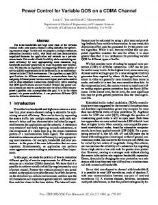
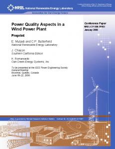
trum of the current harmonics of the load. The method, based on Space vector theory is based on the idea that the fundamental component and the sum of the higher harmonics can be separated by transforming the current vector into a synchronously rotating reference frame and averaging the time function. This way the fundamental component is obtained that, extracted from the original time function, will result in the sum of higher harmonic components, thus the fundamental component and the sum of higher harmonics can be controlled separately. To illustrate the process, Figure 3 shows the calculated closed form trajectory of the mains current, where the fundamental the 5th, 7th, 11th, 13th, 17th and 19th harmonic current components are included with I1 = 100 A, I5 = 20 A, I7 = 14 A, I11 = 9 A, I13 = 7.5 A, I17 = 6 A and I19 = 5 A, while in Figure 4 the trajectory of the same current vec-
(3)
h= 2
but according to the assumption made, only the positive sequence components will be utilized. The aim is controlling the output voltage of the converter shown in Figure 1 to accomplish PQC by reducing or eliminating the higher harmonic current components of im to contain fundamental components only. In practice this goal can be implemented by generating proper current components injected into the common point of the load and mains to cancel the undesired components of iL . In order to design a control system for the purpose of PQC, first it is necessary to sense the specAUTOMATIKA 46(2005) 3–4, 129–134
Fig. 4 Current vector in a synchronously rotating reference frame
131
jardan.qxd
7.2.2006
16:02
Page 132
Time Domain Control of a Power Quality ...
R. K. Járdán, I. Nagy, A. Olasz
tor can be seen transformed into a reference frame rotating with the angular velocity of the fundamental, i.e. fixed to the vector of the fundamental component. As the result of the transformation the fundamental component I m1 becomes a constant vector, the trajectory of the sum of the higher harmonics ∑ ih , forms a closed path and the total mains current is the sum of the above two components. The amount of higher harmonics listed above results in a current THD = 28 %. The Kirchoff's equations for the equivalent circuit of Figure 2 can be written as: im = ∆v
R 1 + sTc 1 1 − iL c R 1 + sT R 1 + sT
vL = vm + im Rm (1 + sTm )
(4) (5)
where: Lm + Lc L , Tc = c , R Rc Lm Tm = , R = Rm + Rc Rm
T=
and ∆v = vc − vm . 4 CONTROL OF THE CONVERTER
When the mains current im is decomposed into fundamental component and the sum of higher harmonics, a controller for providing PQC functions can be realised. The controller should have four inputs that accept the reference signals corresponding to the real and imaginary components of the
fundamental current vector (proportional to the active and reactive power) as well as the reference signals for the components of the higher harmonic current vectors. The basic block diagram of the system representing the control loops that realise of the PQC functions is shown in Figure 5. The high frequency PWM DC/AC converter is fed by the AC/DC converter that converts energy supplied by the high speed synchronous generator. The DC/AC converter is connected to the utility mains via AC link inductors that serve as filters to attenuate higher harmonics of the output current. In the case when the system is operated also as UPS, a group of loads L is separated and fed directly by the system using the energy obtained from the working medium on the mechanical side. In the case of mains failure, the load and the DC/AC converter are isolated from the faulty mains by a static switch. During the transition to UPS operation, the control strategy of the system has to be converted from parallel mode (PM) to stand-alone mode (SAM). In PM, the control loops of the system have to ensure that the energy available on the mechanical side is fed to the mains by keeping power equilibrium between the mechanical and electrical sides. In this mode of operation the PQC should be functioning and provide reactive power to the mains and at the same time ensure that the higher harmonic components, generated by the load, are eliminated. The fundamental reactive power can be higher than required to compensate for the reactive power drawn by the load.
Fig. 5 Block diagram of the control system
132
AUTOMATIKA 46(2005) 3–4, 129–134
jardan.qxd
7.2.2006
16:02
Page 133
R. K. Járdán, I. Nagy, A. Olasz
In SAM the energy balance between the mechanical and electric sides has to be ensured by controlling the flow rate of the working medium as the electric energy consumption is defined only by the load. In this case the output voltage is kept constant, containing only fundamental component, PQC function is not applied. The operation of the control loops is based on the use of space vector quantities. Sensing the mains current in three phases, the current space vector time function is given by the block »Space vector transformation«. The coordinate transformation needed to carry out the separation of the fundamental and the sum of higher harmonics is made by the blocks »Coordinate transformation« and »Calculation Unit«. At the output of the Coordinate transformation block the current space vector time function is given in a synchronously rotating reference frame, in which the fundamental component is a constant vector, while the sum of higher harmonics describes a closed trajectory. By calculating the average values continuously, the Calculation Unit separates the fundamental components and the sum of higher harmonics according to the principle described previously. Thus the Calculation Unit has four outputs yielding the real and imaginary components separately for the two variables.
Time Domain Control of a Power Quality ...
5 SIMULATION RESULTS
A sample of the results of a Matlab/Simulink simulation program developed for studying the static and dynamic behaviour of the system are shown below. In Figure 6 and 7 the higher harmonic current generated by the converter to eliminate the harmonics of the load is shown in real and imaginary components vs. time and in space vector form.
Fig. 6 Real and imaginary components of the higher harmonics generated by the converter
The controllers C1 and C2 accept reference signals for the real and imaginary components of the fundamental mains current. The outputs of these controllers change the phase and magnitude of the internal voltage of the converter. The real component of the current vector is proportional to the active power fed to the mains thus the reference signal is given by the power controller of the system, responsible for the power equilibrium. The imaginary component will be proportional to the reactive power, and its level can be determined according to various strategies. In steady state condition both reference values are constant DC levels. Controllers C3 and C4 are responsible for the elimination of the higher harmonic components generated by the load. The output signals of these controllers are added to the outputs of C2 and C3 to modify the control signals of the PWM controllers of the DC/AC converter. As the task of the controllers C3, C4 is to eliminate the higher harmonic components, the corresponding reference values are: I h*1 x = 0 and I h*1 y = 0.
For the PWM controller the space vector components are transformed back to the stationary reference frame by the unit »Inverse coordinate transformation«. AUTOMATIKA 46(2005) 3–4, 129–134
Fig. 7 Space vector of the higher harmonics generated by the converter in synchronously rotating reference frame
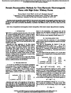
In Figure 8 the error signal of the controller of the higher harmonics is shown in space vector representation. It can be seen that the error signal is below 0.1 pu, i.e. the higher harmonic content of the mains current is reduced by 90 %, i.e a THD 133
jardan.qxd
7.2.2006
16:02
Page 134
Time Domain Control of a Power Quality ...
R. K. Járdán, I. Nagy, A. Olasz
on the application of space vector theory, using an algorithm easy to implement. The transient response of the solution is not fast, but in a PQC system normally this is not relevant. Should it be necessary, the calculation of the average values could be achieved by a faster numerical method at the cost of more sophisticated hardware and software. ACKNOWLEDGEMENT
The authors acknowledge that the research work described in the present paper has been carried out by the financial support of the Control Engineering Research Group of the Hungarian Academy of Science and the National Research Fund (OTKA, T046240, T049640). Fig. 8 Space vector error signal in the controller of the higher harmonics
of 28 % is reduced below 3 %. By a faster controller the quality of the harmonic elimination can further be improved. 6 CONCLUSION
The paper presents a control method for PQC, using a novel algorithm for the extraction of higher harmonic current components. The operation of the controller, exploiting the capabilities of the DC/AC converter of a system that has been developed to generate electric energy by utilizing renewable and waste energies, is shown in the paper. The solution of power quality conditioning is based
REFERENCES [1] S. Bhattacharya, Po-Tai Cheng, D. M. Divan, Hybrid Solutions for Improving Passive Filter Performance in High Power Applications. IEEE Trans. on Industry App., Volume 33, Issue 3, May–June 1997, pp. 732–747. [2] R. K. Járdán, I. Nagy, E. Raaijen, Power Factor Correction in a Co-Generation System. EPE'99, Lausanne, Switzerland, September 7–9, 1999. [3] J. Leuchter, P. Bauer, O. Kurka, H. Polinder, Generator-Converter Set for Mobile Power Sources. 11th International Power Electronics and Motion Control Conference, Riga, Latvia, 2004. [4] I. Rácz, Recording and Harmonic Analysis of Three-Phase Vectors. Periodica Politechnica, Budapest, Vol. 8, No. 4, 1964. (In German). [5] R. K. Járdán, S. B. Dewan, G. R. Slemon, General Analysis of Three-Phase Inverters. IEEE Transactions on Industry and General Applications, Vol. IGA-5, No.6, Nov/Dec, 1969. pp. 672–679.
Upravljanje sustavom za pobolj{anje kvalitete elektri~ne energije u vremenskom podru~ju. ^lanak prikazuje rje{enje sustava za pobolj{anje kvalitete elektri~ne energije uporabom izmjenjiva~a iz sustava razvijenog za kori{tenje obnovljivih i otpadnih izvora energije. Algoritam upravljanja sustavom za pobolj{anje kvalitete elektri~ne energije utemeljen je na primjeni teorije vektorskog prostora, a razvoj cijelog sustava po~ivao je na sveobuhvatnoj primjeni ra~unalnih simulacijskih tehnika. Klju~ne rije~i: upravljanje pretvara~em, kvaliteta elektri~ne energije, simulacija
AUTHORS’ ADDRESSES Rafael K. Járdán1, István Nagy1,2, Attila Olasz1 1 Budapest University of Technology and Economics, Department of Automation and Applied Informatics, Goldmann Gy. ter 3, H-1117 Budapest, Hungary, E-mail:
[email protected] 2 Computer and Automation Institute, Hungarian Academy of Science Kende 13-17, H-111 Budapest, Hungary Received: 2005-12-19
134
AUTOMATIKA 46(2005) 3–4, 129–134