FAC 2005 Preliminary Version
Time Domain Verification of Oscillator Circuit Properties Goran Frehse, Bruce H. Krogh, Rob A. Rutenbar 1 Dept. of Electrical and Computer Engineering Carnegie Mellon University Pittsburgh, PA 15213-3890, USA
Oded Maler 2 VERIMAG Centre Euation, 2 av de Vignate 38610 Gi`eres, France
Abstract The application of formal methods to analog and mixed signal circuits requires efficient methods for constructing abstractions of circuit behaviors. This paper concerns the verification of properties of oscillator circuits. Generic monitor automata are proposed to facilitate the application of hybrid system reachability computations to characterize time domain features of oscillatory behavior, such as bounds on the signal amplitude and jitter. The approach is illustrated for a nonlinear tunnel-diode circuit model using PHAVer, a hybrid system analysis tool that provides sound verification results based on linear hybrid automata approximations and infinite precision computations. Key words: verification, oscillators, analog circuits, hybrid systems, hybrid automata
1
Introduction
Formal methods are widely and successfully used to verify the correctness of digital circuits. So far, no sufficiently powerful verification techniques exist in the domain of analog and mixed-signal circuits. The complexity of the verification problem for such circuits is immense for several reasons. Analog designs have high-dimensional nonlinear dynamics. It is difficult to formally 1 2
Email: {gfrehse|krogh|rutenbar}@ece.cmu.edu Email:
[email protected] This is a preliminary version. The final version will be published in Electronic Notes in Theoretical Computer Science URL: www.elsevier.nl/locate/entcs
Frehse et al.
define the desired behavior of such circuits. Their sensitivity to a variety of physical effects makes it difficult to isolate their behavior and abstract from their interactions. Given this complexity, the initial focus for formal methods should be in the early, block-level design steps. In this paper, we discuss methods to verify design properties of oscillator circuits, which play a fundamental role as a basic design block in many practical applications, by using methods and tools for reachability analysis. Oscillator circuits are designed to produce a periodic signal with small variations in amplitude and phase even when subject to parameter variations and disturbances. We can guarantee conservative bounds on these variations by applying formal verification techniques that are particularly suited to handle nondeterminism and uncertainties. Our models, so-called hybrid automata [1], capture continuous as well as discrete state behavior, and can be used to model nonlinear dynamics. Verification tools exist that guarantee correctness of the results by using exact arithmetic and overapproximations and recently, progress has been made in the efficient computation of reachable states for hybrid systems. We present a set of generic models for measuring and verifying bounds on amplitude variation and (phase) jitter. We provide some experimental results with PHAVer, a hybrid systems tool that compute a guaranteed conservative overapproximations of sets of reachable states [7]. As a benchmark we use a tunnel diode oscillator circuit, as it appears in [10,9]. Model checking of nonlinear analog circuits was first proposed in [10], where the continuous state space is discretized, and an abstract transition relation is computed for the finite, discrete model. Conventional model checking can be applied to this abstraction, but due to the overapproximation only safety properties are preserved. Similarly to the approach in PHAVer, the partitioning of the state space is adapted to the dynamics of the system. The overapproximation of the transition relation in this approach is much larger than the continuous-valued overapproximation of PHAVer. It is not guaranteed to be conservative, and striving for conservativeness in a discretization based approach can quickly lead to an excessive loss of accuracy. In [9], analog circuits were verified using the tool CheckMate [5], which computes an abstract transition relation between user-defined regions of the state space. Optimization is used to guarantee, as much as possible, the conservativeness of polyhedral enclosures of the reachable states, but it is not guaranteed that the global optimum is found. The tool d/dt [2] computes the reachable states for hybrid systems with affine dynamics by discrete time integration, and guarantees conservativeness using an approach that maximizes the normal derivative of the vector field over the faces of the polyhedron. Sets of states are efficiently represented with orthogonal polyhedra. The approach is algorithmically sound because an under- as well as overapproximation is used. Linear analog circuits have been analyzed with d/dt in [6]. All the above tools are not numerically exact, and consequently not formally sound in their overapproximations. While in PHAVer the integration error accumulates, both 2
Frehse et al.
CheckMate and d/dt have the advantage that the overapproximation error does not accumulate over time. The formal background for the overapproximations of hybrid automata with nonlinear and affine dynamics originates in the work of Henzinger et al. [11]. In the following section, we define oscillations and derive properties of oscillations that can be checked using reachability, such as amplitude and phaser jitter. We show hybrid automaton models for monitoring such properties using reachability tools. In Sect. 3, we illustrate how PHAVer can be applied to verify these properties, and provide some experimental results for a tunnel diode circuit in Sect. 4. Finally, we draw some conclusions in Sect. 5.
2
Defining and Verifying Oscillations
Our goal is to take a model of the oscillator of the form x˙ = f (x, p, u), where p represents parameters and u stands for external disturbances, and check whether it exhibits oscillating behavior that is robust under variations in p and all admissible values of u. As a first step we define oscillations, exactly and approximately. The specification may vary from one application to another. The point of the discussion is to study oscillatory behavior in the vicinity of some periodic limit cycle, so we neglect transient behavior and assume a phase error close to zero. For the sake of simplicity, we assume that our requirements describe the desired properties of a scalar signal ξ obtained as a projection of our system onto one variable x of interest. This simplifies the representation of threshold crossings and other behaviors. On scalar domains we will use x ≈ y to indicate that |x − y| < ǫ without being specific about ǫ. 2.1
Reference Signal
The most rigid specification is given by a reference oscillatory behavior, say ¯ = Asin(ωt + φ), ξ(t)
(1)
to which ξ should be close in some metric d: ¯ < ǫ. d(ξ, ξ) Using the pointwise maximum distance ¯ = max|ξ(t) − ξ(t)| ¯ d(ξ, ξ) t∈R+
is equivalent to the property ¯ ∀t ∈ R+ : ξ(t) ≈ ξ(t). 3
(2)
Frehse et al.
This is a reachability property, as it is satisfied if the states of ξ over time ¯ and can be computed in the augmented remain inside an ǫ-envelope around ξ, ¯ state space of ξ, ξ and t. Since the linear oscillator is only marginally stable, it will be numerically difficult to simulate. Alternatively, one could use an explicit, analytically computed, representation of the envelope. In practise, the verification of this property is rather difficult. The infinite time interval would have to be mapped onto a bounded interval [0, T ], e.g., by resetting the reference time for ξ¯ at t = T , which requires the explicit knowledge of T . A conservative reachability analysis usually depends on some type of overapproximation, which would for many circuits result in period that can vary in some interval unless the circuit is designed to be asymptotically stable with respect to the period T . Since the quantification in (2) ranges over all time, any deviation in the period would result in a prohibitively large distance between the two signals. In the following, we will therefore consider properties that are more amenable to practical purposes. 2.2
Arbitrary T-Periodic Behaviors
A less specific property to consider is the periodic time T of ξ. Suppose we know that all signals in question, clean and noisy alike, stay inside a range ¯ is a good under-approximation. 3 Since x can occur more for which the set X than once in a period, we consider signals for which x occurs only once per period in some combination with the signs of the higher derivatives, and for which, to avoid pathological cases, at any time for some k > 0 the derivative dk /dtk x(t) is nonzero. For simplicity, we denote x in the following as a statelike tuple (x′ , ⊲⊳1 , . . . , ⊲⊳m ) where x′ ∈ X, ⊲⊳i ∈ {≤, ≥} and m + 1 is the order of a system producing the signal. Furthermore, we write ξ(t) = x if ξ(t) = x′ and di /dti ξ(t) ⊲⊳i 0 at time t. This will allow us to express properties of ξ ¯ occur. The classical way to in terms of the time points at which values in X express periodicity is ∀t ∈ R+ , n ∈ N : ξ(t) ≈ ξ(t + nT ).
(3)
An alternative and almost equivalent definition (they are equivalent when strict equality is used) can be made by counting the nth occurrence of a value x of ξ. Let τ (x, n) = t iff the nth occurence of x in ξ is at time t. We will later use this formulation to build monitor automata. Equipped with this function we can say: ¯ n, m ∈ N : τ (x, n) ≈ τ (x, m) − (m − n)T. ∀x ∈ X,
(4)
The difference between (3) and (4) is that we quantify in (3) over all positive ¯ i.e., only for the values values of t, while in (4) we do so only for values in X, of x that appear in every ξ. 3
One could define it as the largest set that all signals of interest visit infinitely often.
4
Frehse et al.
Both (3) and (4) are not reachability properties on the original state-space of the system, because they require infinite (bounded but dense) memory. Let us first reduce them to their “one step” equivalents: ∀t ∈ R+ : ξ(t) ≈ ξ(t + T ), ¯ ∀x ∈ X, n ∈ N : τ (x, n) ≈ τ (x, n + 1) − T.
(5) (6)
The properties above are equivalent to (3) and (4) only if we use strict equality, because approximate equality is not transitive. In the case of (5), the memory consists of a function z : [0, T ) 7→ X such that at any instant t, z(t′ ) = ¯ × {≤, ≥}m 7→ R+ with ξ(t − t′ ). For (6), the memory is a function w : X w(x) = τ (x, nx ), with nx being the number of times x already occured in ξ. 2.3
Reduction to Finite Memory
We now introduce approximations with finite memory to characterize these properties. The idea is very simple: just replace the quantification over all t or x by finitely many values for each period. Without loss of generality, let us pick zero for both t and x, and some fixed tuple of signs ⊲⊳ for the derivatives. The two formulae simplify to: ∀n ∈ N : ξ(nT ) ≈ ξ((n + 1)T ), ∀n ∈ N : τ (0, n) ≈ τ (0, n + 1) − T.
(7) (8)
In (7) we say that we roughly get the same value every T time units. In (8) we say that zero crossings are roughly T spaced. Mechanically speaking, these properties can be checked by adding a clock to the system as well as a memory variable which can remember either time or value. For the first property, also called cycle-to-cycle amplitude variation, we remember the last value of x at ξ(nT ) and when the clock reaches T we compare the current value of ξ with the previous one, reset the clock and update the memory. For the second property, called period jitter, we compare the value of the clock with the memory every time we encounter ξ(t) = 0 and then reset the clock and update the memory. In order for x to be encountered only once per period, we take into account the derivatives (or other state variables), which are encoded with discrete states. 2.4
Monitor Automata
Figures 1 and 2 show monitor automata for verifying bounds on the amplitude variation and the phase jitter using reachability analysis. They contain a special error location, and the properties are fulfilled if this error location is not reachable. The simplest form of amplitude variation, the variation over a single cycle, is checked by the monitor in Fig. 1(a). It has a clock that measures the elapse of the cycle period T . If at the end of the cycle x can be too far away from zero, an error location is reachable and the property 5
Frehse et al.
(a) Single cycle
(b) Absolute
(c) Cycle-to-cycle
Fig. 1. Monitor automata for the amplitude variation
is violated. The monitor in Fig. 1(b) checks whether for all multiples of the period T the state is in the vicinity of the zero crossing, i.e., whether ∀n ∈ N : ξ(nT ) ≈ 0.
(9)
The monitor is initially in the state cycling. A clock t measures the period, and at t = T two transitions are possible: If x is close to zero, the clock is reset and the monitoring continues. If x is outside of the ǫ-region around zero, the monitor enters the error location and the property is violated. As discussed at the end of Sect. 2.1, the absolute variation with respect to an explicit period T is practical only in special cases. By contrast, the cycle-to-cycle variation of the amplitude, i.e., property (7), is of practical usefulness since it allows for some deviation from the period T . A corresponding monitor is shown in Fig. 1(c). The value of x at t = T is compared against the value xˆ memorized at the last period. Monitoring the jitter is slightly more complicated, because we have to uniquely identify one zero crossing per cycle. We demonstrate this for a second order system, which has at most two zero crossings that can be distinguished by the sign of the derivative x. ˙ The monitor in Fig. 2(a) verifies the period jitter, i.e., property (8). It has a clock t and features three locations, one for positive values and one for negative values of x, and one error location. The automaton is initially in the location cycling pos and assumes a positive derivative for x. The first half of the cycle takes place in this location, until the zero crossing is hit with a negative derivative x, ˙ which triggers a transition to the location cycling neg. There the second half of the cycle occurs, until the zero crossing is hit with a positive derivative. At this point two transitions are possible: If the clock t is within ǫ units of the period T , the clock is reset and the cycle recommences in location cycling pos. Otherwise the monitor enters the error state. 6
Frehse et al.
(a) Period
(b) Cycle-to-cycle
Fig. 2. Monitor automata for the phase jitter
The monitor in Fig. 2(b) verifies the cycle-to-cycle jitter, i.e., the property ∀n ∈ N : τ (0, n + 1) − τ (0, n) ≈ τ (0, n) − τ (0, n − 1).
(10)
It operates similarly to the monitor in Fig. 2(a), except that the previous cycle time is stored in a variable tˆ, and after each new cycle the time is compaired against tˆ instead of T . We finally turn to the problem of obtaining bounds on the amplitude variation and phase jitter instead of verifying a priori known bounds. The monitor automata from Figs. 1 and 2 are easily adapted by removing the error location. The bounds on the amplitude variation can then be obtained from the states in the intersection of the set of reachable states with the constraint t = T . For the bounds on the phase jitter, we regard the reachable states in the location cycling neg, intersected with the constraint x = 0.
3
Implementation in PHAVer
We provide experimental results for some of the monitor automata in the previous section. For computing the set of reachable states we use the verification tool PHAVer [7], which can compute exact reachability for linear hybrid automata 4 (LHA) [1]. In linear hybrid automata, the invariants and transitions given by linear predicates, and the dynamics by conjuncts of linear constraints aTi x˙ ⊲⊳i bi ,
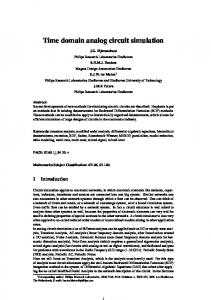
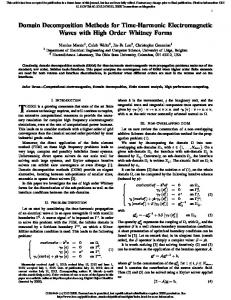
ai ∈ Zn , bi ∈ Z, ⊲⊳i ∈ { 0.25 V or Vd < 0.25 V. The reachable states, shown in Fig. 6, guarantee the period to be between 13.52 µs and 13.86 µs. The computation takes 1997 s (1463 MB).
5
Conclusions
This paper presents a method for constructing monitor automata for oscillator circuits based on the analysis of scalar signal properties related to the specifications of interest. Here we consider the amplitude and phase jitter. The objective is to construct hybrid system models that are amenable to finite-time reachability analysis. Typically reachability computations for hybrid systems focus on the transient system behavior starting from a set of initial conditions. The present work aims to verify properties of the asymptotic, “steady state” behavior of a circuit. We are interested in extending this approach to verify other properties that are commonly analyzed using frequency domain techniques. 11
1.2
0.6
1.0
0.5
0.8
0.4 V [V]
I [mA]
Frehse et al.
0.6
0.3
0.4
0.2
0.2
0.1
0.0
0
2
4
6 8 t [1e−9s]
10
12
0.0
14
0
2
(a) Current IL
4
6 8 t [1e−9s]
10
12
14
(b) Voltage Vd
1.2
0.6
1.0
0.5
0.8
0.4 V [V]
I [mA]
Fig. 5. Reachable states of the circuit and the amplitude monitor of Fig.1(a)
0.6
0.3
0.4
0.2
0.2
0.1
0.0
0
2
4
6 8 t [1e−9s]
10
12
0.0
14
(a) Current IL
0
2
4
6 8 t [1e−9s]
10
12
14
(b) Voltage Vd
Fig. 6. Reachable states of the circuit and the phase jitter monitor of Fig.2(a)
References [1] Alur, R., C. Courcoubetis, N. Halbwachs, T. A. Henzinger, P.-H. Ho, X. Nicollin, A. Olivero, J. Sifakis and S. Yovine, The algorithmic analysis of hybrid systems, Theoretical Computer Science 138 (1995), pp. 3–34, a preliminary version appeared in Proc. 11th Int. Conf. Analysis and Optimization of Systems: Discrete-Event Systems (ICAOS), LNCIS 199, Springer, 1994, pp. 331-351. [2] Asarin, E., T. Dang and O. Maler, The d/dt tool for verification of hybrid systems, in: Brinksma and Larsen [4], pp. 365–370. [3] Bagnara, R., E. Ricci, E. Zaffanella and P. M. Hill, Possibly not closed convex polyhedra and the Parma Polyhedra Library, in: M. V. Hermenegildo and G. Puebla, editors, Static Analysis: Proc. Int. Symp., LNCS 2477 (2002), pp. 213–229. [4] Brinksma, E. and K. G. Larsen, editors, “Computer Aided Verification, 14th International Conference, CAV 2002, Copenhagen, Denmark, July 27-31, 2002,
12
Frehse et al.
Proceedings,” LNCS 2404, Springer, 2002. [5] Chutinan, A. and B. H. Krogh, Computational techniques for hybrid system verification, IEEE Trans. on Automatic Control 48 (2003), pp. 64–75. [6] Dang, T., A. Donze and O. Maler, Verification of analog and mixed-signal circuits using hybrid system techniques, in: Formal Methods in Computer-Aided Design (FMCAD 2004), Austin, Texas, November 14-17, 2004, 2004. [7] Frehse, G., Phaver: Algorithmic verification of hybrid systems past hytech, in: M. Morari and L. Thiele, editors, Hybrid Systems: Computation and Control (HSCC’05), Mar. 9–11, 2005, Z¨ urich, CH, 2005, PHAVer is available at http://www.cs.ru.nl/∼goranf/. [8] Frehse, G., Z. Han and B. H. Krogh, Assume-guarantee reasoning for hybrid i/o-automata by over-approximation of continuous interaction, in: Proc. IEEE Conf. Decision and Control (CDC’04), Dec. 14–17, 2004, Atlantis, Bahamas, 2004. [9] Gupta, S., B. H. Krogh and R. A. Rutenbar, Towards formal verification of analog designs, in: Proc. IEEE Intl. Conf. on Computer-Aided Design (ICCAD2004), Nov. 7–11, 2004, San Jose, CA (USA), 2004. [10] Hartong, W., L. Hedrich and E. Barke, On discrete modeling and model checking for nonlinear analog systems., in: Brinksma and Larsen [4], pp. 401–413. [11] Henzinger, T. A., P.-H. Ho and H. Wong-Toi, Algorithmic analysis of nonlinear hybrid systems, IEEE Transactions on Automatic Control 43 (1998), pp. 540– 554.
13