Time Synchronisation Error and Calibration in Integrated GPS/INS Systems Weidong Ding, Jinling Wang, Yong Li, Peter Mumford, Chris Rizos
ABSTRACT- The necessity for precise time synchronisation of measurement data from multiple sensors is widely recognised in the field of GPS/INS integration. Having precise time synchronisation is critical for achieving high data fusion performance. The limitations and advantages of various time synchronisation scenarios and existing solutions are investigated in this paper. A criterion for evaluating synchronisation accuracy requirements is derived based on the comparison of the Kalman filter innovation series and the platform dynamics. An innovative time synchronisation solution using a counter and two latching registers is proposed. The proposed solution has been implemented with off-the-shelf components and tested. The resolution and accuracy analysis shows that the proposed solution has the capability to reach a time synchronisation accuracy at 0.1ms level if INS could provide hard-wired timing signal. A synchronisation accuracy of 2 ms has been achieved when the test system was used to synchronise a low-grade MEMS IMU which has only an RS-232 data output interface. Keywords- GPS, INS, time synchronisation, multi-sensor integration Weidong Ding (email:
[email protected]), Jinling Wang (email:
[email protected]), Yong Li (email:
[email protected]), Peter Mumford (email:
[email protected]), Chris Rizos (email:
[email protected]) are with the Satellite Navigation and Positioning Group, School of Surveying and Spatial Information Systems, University of New South Wales, Sydney, NSW 2052, Australia This research is supported by the Australian Cooperative Research Centre for Spatial Information (CRC_SI) under project 1.3 ‘Integrated Positioning and Geo-referencing Platform’.
ETRI Journal
I. Introduction The Global Positioning System (GPS) receiver and Inertial Navigation System (INS) unit are two important sensors for providing position and attitude information for geo-referencing systems. A GPS/INS integrated system has many applications in surveying, remote sensing, mapping, and navigation. With optimal data fusion, the GPS could ensure long term geopositioning accuracy and stability; while the INS could provide attitude information and partially mitigate against GPS signal outages. Time synchronisation between GPS and INS measurements is a common concern when implementing GPS/INS integrated systems. Since the GPS receiver and INS unit are two separate (self-contained) subsystems, the clock difference and data transmission latency could cause data alignment discrepancies during the data fusion stage. Such alignment discrepancy may render the data fusion suboptimal. In some applications, the time synchronisation of additional sensors, such as barometer, odometer, and imaging sensor, might be necessary. The time synchronisation issue has been extensively reported in the research literature. The report on mobile multi-sensor systems by the International Association of Geodesy (IAG) working group [1] acknowledges its importance. The proposal for IEEE inertial systems standard [2] suggests that the synchronisation of the INS internal clock to an external time reference like the GPS clock is an important issue to be addressed. In this paper a detailed analysis of the limitations and advantages of different time synchronisation scenarios and existing solutions is presented. A criterion for evaluating synchronisation accuracy requirements is developed based on the comparison of the Kalman filter innovation series and the
1/9
platform dynamics. An innovative time synchronisation solution using a counter and two latching registers is proposed. The proposed solution is verified using a test system implemented with off-the-shelf components. Without INS hard-wired timing signal, as reported in test results, a synchronisation accuracy of 2 ms was achieved when the test system was used to synchronise a low-grade INS sensor which is manufactured with Micro-Electro-Mechanical Systems (MEMS) technology, and has only an RS-232 data output interface.
II. Existing Solutions The GPS time is typically used as a time reference for GPS/INS integrated systems. In addition to outputting positioning data and time messages through a serial data link, most GPS receivers provide a 1 pulse-per-second (PPS) electrical signal indicating the time of the turnover of each second. The alignment of the 1PPS signal edge to standard GPS time is normally better than 1µs [3]. The inertial sensors used in GPS/INS integrated systems can be in the form of an Inertial Sensor Assembly (ISA), Inertial Measurement Unit (IMU), or inertial navigation system (INS) according to IEEE’s definition. Depending on what information is extracted from them and their electrical interfaces, different time synchronisation strategies may be employed.
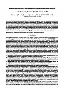
1. Analogue Interface A successful implementation under this scenario is described in detail by [4] and [5], and is illustrated in Figure 1. The GPS 1PPS signal is used to trigger a 10 kHz 8-channel 16-bit analogue-to-digital (A/D) converter so that the starting time of every 10,000 samples is synchronized to the GPS time. The A/D converter simultaneously samples the analogue outputs from individual accelerometers, gyros and temperature sensors. The samples are averaged over 0.01s and sent for GPS/INS integration processing. A similar solution has been proposed by [6], in which a 0.4 milliseconds synchronisation accuracy has been achieved using off-the-shelf components. The details concerning the construction of a synchronised A/D sampling circuit have been given by [7]. Time synchronisation implemented in A/D sampling circuits can be very precise (better than 1µs is possible). The coincidence of GPS and INS sampling at the turnover of each GPS second (assume 1Hz GPS data rate) eliminates the need for interpolation during data processing.
ETRI Journal
Pseudorange
GPS receiver
Carrier phase
1 PPS Synchronization Signal Inertial Sensor Assembly
GPS/INS Data Processing
16-bit A/D 8 Channels 10kHz
External Sampling Circuit
8 Analogue Signals
Fig. 1 Time synchronisation scheme proposed by [5]
However, not all commercial INS sensors provide analogue outputs. Adapting existing INS interfaces to the synchronised A/D sampling circuit is not a trivial task. Even some manufacturers may provide INS sensors with analogue outputs, such as in the case of the Xbow IMU400CC, the output measurements normally go through an internal pre-processing procedure which includes analogue-to-digital conversion, raw sampling data manipulation, and digital-to-analogue conversions. The delays caused by those processes are hard to estimate. Without using commercial INSs, individual inertial sensors are available on the market for building up proprietary INSs. However, their usage is largely limited to the lower end applications. This is because there are so many factors limiting them from reaching a high performance, which might include errors in mounting axes alignment, mounting base deformation, electrical circuit noise, and the lack of high precision calibrations using professional equipment. As will be discussed in section III, using low grade a INS might not need to have a time synchronization accuracy as high as for high grade INSs.
2. Digital Interface 100 PPS INS
Timing Module
Event discrete Event interrupt, Event time RS-422
Integration processor
1 PPS GPS receiver
10.23 MHz 1 PPS interrupt
RS-422
Fig. 2 A synchronisation solution proposed by [8]
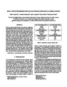
Figure 2 shows a conceptual solution proposed by [8] where an INS sensor has a digital data interface. The timing module is designed to accept the GPS 1PPS signal, and the 10.23MHz signal which is generated from the GPS P-code chipping rate. The timing module generates synchronised 100Hz PPS signal and passes it to the INS sensor. The sampling of inertial sensor
2/9
measurements is synchronised to this 100Hz PPS signal. The 1PPS signal is also introduced into the integration processor to define the beginning of each second. The INS data can thus be time-tagged according to GPS time received through an RS422 link. The limitation of this solution is that the INS sensor has to be able to accept GPS PPS signals, which is very unlikely.
methods have been developed to estimate time synchronisation errors in data fusion algorithms [11]. Nevertheless, a hardware circuit is still necessary to provide initial data alignment; and the time synchronisation accuracy is comparatively low in this case. Due to the variety of possible time synchronisation scenarios, there are some other non-typical solutions [12-14] applied under certain situations, which will not be detailed here.
III. Error Propagation Considering a multivariable linear discrete system for the integrated GPS/INS system:
x k = Φk −1x k −1 + w k −1
(1)
z k = Hk x k + v k
where x k is (n×1) state vector, Φk is (n×n) transition matrix, z k is (r×1) observation vector, H k is (r×n) observation matrix. w k and v k are uncorrelated white Gaussian noise sequence with means and covariances: Fig. 3 Synchronisation scheme introduced by [9-10]
In [9-10] a successful implementation using the digital interface to synchronise the Litton LN100, Honeywell HG1700 and Xbow IMU400C (see Figure 3) is described. In this scheme, the timing is accomplished by using the high precision PC clock as a common time base. A hardware timer which is running with 1 microsecond resolution provides the link between the GPS time and the PC time. At every transition of the 1PPS signal the hardware saves a record. Through an interrupt, the software samples both the timer and the PC time and stores all the values for later processing. The transformation between GPS and PC time base is done in two steps: first, GPS vs. Timer; and then, PC vs. timer. One limitation in using the digital interface is the necessity of data interpolation in order to make INS data coincide with GPS data in the Kalman filter measurement update. This is due to the asynchronous measurement sampling of the GPS and the INS sensors. When the INS sampling rate is 100Hz and the GPS sampling rate is 1Hz, a maximum misalignment of 5 ms can only be bridged using an interpolation technique. Besides a digital interface, some INS sensors also output an electrical PPS signal to indicate the validation of the measurement data (similar to the 1PPS generated by a GPS receiver). With the INS PPS signal, the INS internal preprocessing latencies can be determined and compensated for. When the INS sensor does not have a PPS signal output, the precise determination of the INS internal processing latency and communication latency is a challenge. Some software
ETRI Journal
E ( wk ) = E ( vk ) = 0
(
)
E w k vTi = 0 i=k
⎧Q E w k w Ti = ⎨ k ⎩0 ⎧R E v k v Ti = ⎨ k ⎩0
( (
)
(2)
i≠k i=k
)
i≠k
where E {} ⋅ denotes the expectation function. Qk and R k are covariance matrix of process noise and observation errors, respectively. The KF state prediction and state covariance prediction are: xˆ k− = Φk −1xˆ k −1 T ˆ− =Φ P ˆ P k k −1 k −1Φk −1 + Q k −1
(3)
The Kalman measurement update algorithms are:
(
ˆ − HT H P ˆ− T Kk = P k k k k Hk + R k
(
xˆ k = xˆ k− + K k z k − H k xˆ k−
)
)
−1
(4)
ˆ = (I − K H ) P ˆ P k k k
− k
where K k is the Kalman gain, which defines the updating weight between new measurements and predictions from the system dynamic model. It is well known that the errors in the vertical channel of a Schuller-tuned INS tend to grow exponentially with time, while the errors in the horizontal channels tend to grow no faster than sinusoidally with linearly increasing envelop. To deal with the large INS navigation errors and modelling non-
3/9
temporal filtering effect of the Kalman filter, the white and Gaussian elements of the error ε would be damped out as the filtering process becomes stabilised. The non-white and nonGaussian part would remain as an estimation bias. The impact of the synchronisation error can be numerically analysed by adding intentional time delays to INS data, and investigating their influence on the integration results. When z ( t ) = rGPS ( t ) − rINS ( t ) (5) different increments of time delay are added, the positioning errors steadily increase as the time delay becomes larger. The = rGPS ( t ) − rINS ( 0 ) + ∫ v INS ( 0 ) + ∫∫ a ( t ) same trend is observed when the magnitude of the time delay Where rGPS ( t ) is the GPS position measurements, becomes negative, which is the case when the INS clock bias is rINS ( 0 ) , v INS ( 0 ) are the INS initial position, velocity and negative. More detailed results are presented in [16]. In general, the time synchronisation accuracy required by the a ( t ) is the acceleration measured by INS sensors under proper coordinate frame. The integration symbol integrated GPS/INS system can be evaluated using (8). If ∫ represents the integration within one GPS sampling period. (10) Assume that INS initial position and velocity are known. If ζ k