a notation for TC specifications in behavioral VHDL and discuss some ..... Fig. 4. An ETPN controll part and its corresponding VHDL code. S1. S2. S5. S3. S4. S6. C. C .... Such a shortcoming will be eliminated with a complete design, like that in ...
Timing Constraint Specification and Synthesis in Behavioral VHDL Petru Eles*, Krzysztof Kuchcinski†, Zebo Peng†, and Alexa Doboli* * Computer
Science and Engineering Department Technical University of Timisoara Romania Abstract
This paper describes two methods to specify timing constraints in behavioral VHDL for high-level synthesis purposes. The first method specifies timing constraints on sequences of statements by using predefined procedures. The second method provides support for specification of timing constraints across process borders based on concurrent assert statements on signal events. The paper discusses also an approach to synthesize hardware with timing constraints and concentrates in particular on how to ensure consistency between the behavior of the simulation model and that of the synthesized hardware.
1. Introduction A high-level synthesis (HLS) system performs two main tasks: resource allocation and operation scheduling [6]. The time schedule of operations in the final hardware implementation generated by a HLS algorithm is determined by the optimization decisions made during synthesis. Therefore, a high level algorithmic description accepted for HLS very often contains no timing information. Some design requirements can, however, impose certain timing restrictions on the functionality of the specified system [10]. Requirements on the timing aspects of a design can be incorporated as timing constraints (TCs) in the behavioral specification submitted to the synthesis system. Verification of consistency and operation scheduling under timing constraints are discussed in [2] and [9]. In this paper we propose a notation for TC specifications in behavioral VHDL and discuss some aspects concerning synthesis with such constraints. We consider the following main requirements for a notation capturing TCs for high-level synthesis with VHDL: • specification of minimal, maximal, exact, and range constraints between arbitrary statements; • specification of nested TCs; • simulation of the VHDL design before synthesis, with some estimated values for the TCs; This work has been partially sponsored by the Swedish National Board for Industrial and Technical Development (NUTEK).
†
Dept. of Computer and Information Science Linköping University Sweden
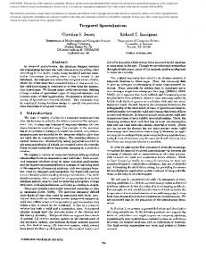
• high-level synthesis with TCs, preserving correspondence between the behavior of the synthesized hardware and that of the simulation model; • back-annotation of the synthesized times for post-synthesis behavioral simulation; • simplicity, readability, and clarity of the notation, and integration into the overall language concept. The proposed notation is implemented in the VHDL frontend of the CAMAD high-level synthesis system designed at Linköping University [12, 4]. In Fig. 1 we show the overall structure of the system, including high-level synthesis from a behavioral VHDL specification with TCs to a register-transfer level hardware structure and back-annotation of the input specification for post-synthesis simulation. One important aspect of CAMAD is its ability to synthesize VHDL specifications consisting of several interacting processes [5]. Accepting for synthesis TCs in the context of VHDL processes interacting through signals generates difficult semantic problems. Some solutions will be presented for preserving correspondence between the behavior of the synthesized hardware and that of the simulation model, while accepting both TCs and interacting VHDL processes for synthesis. This paper is divided into six sections. Section 2 discusses possible solutions for TC specification and evaluates their advantages and shortcomings. Section 3 presents our approach to TC specification with predefined procedures. Section 4 explores the problems concerning VHDL simulaback-annotated VHDL model
back-annotated model generator VHDL specification
VHDL simulator
VHDL front-end
synthesized times for back-annotation
internal design representation timing analysis & HL synthesis RT level structure
Fig. 1. High-level synthesis with timing constraints.
tion semantics in the context of synthesis with TCs and presents our solutions. In section 5 we introduce a mechanism for TC specifications across process borders. Finally, section 6 presents our conclusions.
2. Specification of TCs Some hardware description languages, such as HardwareC [9] and DSL [2], include as part of their definitions a notation for TC specification. There is, however, no provision in VHDL [8] for the specification of a minimum, maximum or range of acceptable TC values for synthesis. According to VHDL standard semantics both after clauses in signal assignment statements and wait statements with time clauses are used to express strict simulation timing. Thus, if VHDL is used as an input language for high-level synthesis, some conventional notation has to be adopted for the TC specification. Some HLS systems accepting VHDL as an input language, such as CALLAS [1], rely on exact synthesis of a user specified number of clock cycles between certain operations. In the VHDL subset accepted by CALLAS, timing specification is based on a set of predefined procedures. The CALLAS approach in fact requires scheduling decisions to be taken by the designer and thus limits the freedom for synthesis optimization. In [7] a similar approach to timing specification is proposed. In addition, the so called “interface procedures”, for the specification of the interface part of the circuit, are introduced. They are synthesized by specialized tools, and signal assignments and wait for statements are accepted only inside such a procedure. The use of predefined procedures for TC specification is also advocated in [11]. Synopsis VHDL tools use both commented lines and attributes to specify TCs [13]. The main drawback with these two methods is that no simulation of the behavioral model is possible, either before or after synthesis. The TCs are ignored by VHDL simulators and are recognized only by the synthesis tools.
3. Predefined Procedures for TC Specification In order to express TCs in a behavioral VHDL description for high-level synthesis, a conventional notation is needed to specify restrictions on the execution time of a sequence of statements after synthesis. According to our requirements we consider the following restrictions on the execution of a sequence of operations: • Minimal delay: it has to take at least a certain time; • Maximal delay: it has to take at most a certain time; • Range delay: it has to take a time between two limits; • Exact delay: it has to take exactly a given time. For each of the above TC specifications a predefined procedure is implemented. To specify a certain restriction the user calls the corresponding predefined timing procedure
PACKAGE constraints IS SUBTYPE time_1 IS TIME RANGE 150 ns TO 150 ns; SUBTYPE time_2 IS TIME RANGE 0 ns TO 200 ns; SUBTYPE time_3 IS TIME RANGE 100 ns TO TIME’HIGH; SUBTYPE time_4 IS TIME RANGE 100 ns TO 1200 ns; CONSTANT constr_1:time_1; CONSTANT constr_2:time_2; CONSTANT constr_3:time_3; CONSTANT constr_4,constr_5:time_4; END constraints; PACKAGE BODY constraints IS -- the values are estimated for pre-synthesis simulation; -- they will be back-annotated after synthesis. CONSTANT constr_1:time_1:=150 ns; CONSTANT constr_2:time_2:=100 ns; CONSTANT constr_3:time_3:=130 ns; CONSTANT constr_4:time_4:=500 ns; CONSTANT constr_5:time_4:=650 ns; END constraints; . . . PROCESS VARIABLE anchor1, anchor2: TIME; . . . BEGIN . . . ANCHOR(anchor1); . . . EXACT_TIME(constr_1, anchor1); . . . IF cond THEN ANCHOR(anchor2); . . . MAX_TIME(constr_2, anchor2); ELSE . . . ANCHOR(anchor2); . . . MIN_TIME(constr_3, anchor2); . . . END . . IF; . RANGE_TIME(constr_4, anchor1); . . . END . . PROCESS; .
Fig. 2. Timing constraints on sequences of statements.
passing as an argument the value of the time interval associated with the constraint. The location of the call determines the end point (the sink) of the constrained sequence. The starting point of the statement sequence is defined by an anchor. To refer to the anchor, each call to a predefined timing procedure contains a second argument representing a variable of type time. The anchor point is defined by the precedent call to a timing procedure that contains as an argument the same time variable. An example of TC specifications is given in Fig. 2, where the constrained sequences are indicated by arrows. The predefined package time_restrict, implemented as part of our design environment, exports the timing procedures anchor, range_time, min_time, max_time, and exact_time. It is natural that both the anchor and the sink of a TC have to be located in the same branch of anif statement, variant of a case, and body of a loop, procedure, or process. The time values associated with the constraints are specified as constants of a subtype of type time. Similar to the approach proposed in [3], at synthesis the ranges of these subtypes are identified as the constraint limits. The values of the time constants are ignored by the synthesis tool. For simulation, the constraint associated with a time constant (the range corresponding to its type) is not relevant, but its value is considered. This value is passed as a parameter to the procedure exported by the package time_restrict and is considered by the VHDL simulator. In our example these values are specified in the body of package constraints. For pre-synthesis simulation the values are estimated by the
Fig. 3. Part of the package time_restrict.
designer; after synthesis they are automatically replaced at back-annotation with the synthesized times which are then considered for post-synthesis simulation. At simulation the four procedures range_time, min_time, max_time, and exact_time act in a similar way. We illustrate this with a sequence from the package body time_restrict in Fig. 3. Simulation of the delay on the constrained sequence is solved by the wait for statement in the procedure wait_delay. The actual wait is for the amount of time (to_wait) left after previous waits executed inside the constrained sequence corresponding to the specified anchor. This solution supports, according to our requirements, nested TCs. The synthesis tool ignores the body of the predefined timing procedures. The procedures are recognized by their name and the corresponding constraint is translated into the internal design representation, with time limits corresponding to the range of the subtype associated to the time constant.
4. Simulation/Synthesis Correspondence The most difficult issues concerning hardware synthesis of VHDL specifications originate from the VHDL semantics of signal assignments, wait statements, and the timing model, which are specified in terms of simulation. We have developed and implemented two strategies for high-level synthesis of behavioral VHDL descriptions containing interacting concurrent processes [5]. These strategies preserve the partial ordering relation of operations on signals and ports from the simulation model to the synthesized hardware structure. Thus we achieve simulation/synthesis correspondence which means that the simulation model and the synthesized hardware react with the same values (sequences of values) of the signals and ports to identical sequences of stimuli applied at the inputs. For VHDL specifications containing TCs, simulation/ synthesis correspondence implies the conditions stated above and the correspondence between the timing behavior of the constrained sequences in the synthesized hardware
4. 1. Design Representation The internal design representation of CAMAD, called ETPN (Extended Timed Petri Net) [12], has been developed to capture the intermediate results during the high-level synthesis process. The ETPN representation, which VHDL specifications are translated to, consists of a control part and a data path. The control part is represented as a timed Petri net with restricted transition firing rules. Transfer of data in the data path is controlled by control signals coming from the control part. A control signal is generated when a token is deposited at a Petri net place. A Petri net transition may be guarded by one or several conditions produced from the data path. It may be fired when it is enabled (all its input places have a token) and the guarding condition is true. In Fig. 4 we show an ETPN control part and its corresponding VHDL sequence. TCs are captured by the ETPN representation as additional arcs in the control part (represented as dotted lines in Fig. 4). They are attributed with the time limits associated to the constraint and with an identifier corresponding to the respective time constant (the identifier is provided for back-annotation). Such an arc is placed between the control places corresponding to the start and to the end of the constrained sequence.
4. 2. Synthesis of Concurrent VHDL Processes In [5] we presented two models for specifying interacting VHDL processes, the unrestricted model and the reduced synchronization model. The unrestricted model offers the freedom to express process interaction at the level of signal assignments and wait statements. From the point of view of synthesis the model implies practically the hardware implementation of the simulation cycle in order to preserve simulation/synthesis correspondence. This means that processes have to wait for each other, until all of them are executing a wait statement, before updating the signal values. The synthesis strategy corresponding to the reduced synchronization model does not reproduce the simulation cycle in hardware, while maintaining simulation/synthesis corre-
S1 S2 C
C S3
S5 S4
[100 ns, -1, constraints.constr_3]
PROCEDURE range_time(delay: TIME; t_anchor: INOUT TIME) IS BEGIN wait_delay(delay, t_anchor); END . . range_time; . PROCEDURE anchor(t_anchor: OUT TIME) IS BEGIN t_anchor:=NOW; -- set time for anchor END anchor; . . . END time_restrict;
and in the back-annotated simulation model.
[100 ns, 1200 ns, constraints.constr_4]
PACKAGE BODY time_restrict IS PROCEDURE wait_delay(delay: TIME; t_anchor: INOUT TIME) IS VARIABLE to_wait: TIME; BEGIN to_wait:=delay-(NOW-t_anchor); -- time left for wait IF to_wait>=0 THEN WAIT FOR to_wait; ELSE ASSERT FALSE--already more time spent then expected REPORT "timing restriction error" SEVERITY WARNING; END IF; t_anchor:=NOW; -- set time for anchor END wait_delay;
. . . ANCHOR(anchor1); x:=z+1; -- S1 IF x>0 THEN -- S2 ANCHOR(anchor2); x:=a+2; -- S3 y:=x-b; -- S4 MIN_TIME(constr_3,anchor2); ELSE x:=a*2; -- S5 END IF; y:=y*x; -- S6 RANGE_TIME(constr_4,anchor1); . . .
S6
Fig. 4. An ETPN controll part and its corresponding VHDL code.
P1:
anchor(t1);
P2:
anchor(t2); [...]
[...] exact_time(3 ns, t1);
exact_time(15 ns, t2);
Fig. 5. Parallel processes with timing constraints.
spondence. According to this model VHDL processes interact using a synchronous message passing mechanism with predefined send/receive commands. Communication channels are represented by VHDL signals. Assignment of a value to a signal is done with a send command. Processes that refer to the signal will wait until a value is assigned to it, by calling a receive command. The correct behavior of the hardware described conforming to the reduced synchronization model does not rely on the implicit synchronization enforced by the simulation cycle. Thus the synthesis strategy corresponding to this model does not need to implement the simulation cycle in the synthesized hardware [5].
4. 3. Simulation/Synthesis Correspondence with the Unrestricted Model
4. 4. Simulation/Synthesis Correspondence with the Reduced Synchronization Model As mentioned in section 4.2, synthesis with the reduced synchronization model does not implement global synchronization in hardware. The correct behavior of a hardware specified in VHDL according to this model does not rely on Q1:
x := ...s...; anchor(t2);
Q2: s =t1 AND NOW-a’LAST_ACTIVE