EUROPEAN ORGANIZATION FOR NUCLEAR RESEARCH CERN/LHCC 2000-002 LEB Status Report/RD12 3 January 2000
Status Report on the RD-12 Project
Timing, Trigger and Control Systems for LHC Detectors Ashton, M. Humphries, J. Honeywell, Aldermaston Villalobos Baillie, O. Birmingham Univ. Christiansen, J. Cittolin, S. Ermoline, Y. Farthouat, P. GŠllnš, P. Jarron, P. Marchioro, A. Moreira, P. Pollet, L. Racz, A. Taylor, B.G. Varela, J. CERN Schmidt, H.R. Darmstadt GSI Hubert, J.-C. McFarlane, G. Lemo, Ecublens and Worthing Da Silva, J.C. Lisbon, Lab. Instrum. e Particules Genat, J.-F. Paris VI and VII Univ. Hallsal, R.N.J. Haynes, W.J. Rutherford Appleton Lab Ferrer-Prieto, J. Valencia, Polytechnical Univ. Toifl, T.H. Vienna, Inst. Kernphysik, Technische Universitaet
Spokesman: Taylor, B.G.
Contents
1 2 3 4 5 6 7 8 9 10 11 12 13 14 15 16 17 18 19 20 21 22 23 24 25
Introduction . . . . . . . RD12 membership . . . . LHC timing distribution . . PCR TTC transmitter . . . Phase stability . . . . . . Faraday cage link . . . . . TTCmi . . . . . . . . . . LHCrx . . . . . . . . . . TTCcf . . . . . . . . . . TTCtx . . . . . . . . . . LHC-structured test beams . Optical tree couplers . . . Optical fibre . . . . . . . TTCvi . . . . . . . . . . ALICE requirements . . . . TTCvx . . . . . . . . . . TTCrx . . . . . . . . . . TTCrx for ATLAS . . . . . TTC in LHCb . . . . . . . Synchronization . . . . . LHC beam instrumentation Laser safety . . . . . . . TTC mailing list . . . . . . Conclusion . . . . . . . . Acknowledgment . . . . . References . . . . . . . .
. . . . . . . . . . . . . . . . . . . . . . . . . . . . . . . . . . . . . . . . . . . . . . . . . . . . . . . . . . . . . . . . . . . . . . . . . . . . . . . . . . . . . . . . . . . . . . . . . . . . . . . . . . . . . . . . . . . . . . . . . . . . . . . . . . . . . . . . . . . . . . . . . . . . . . . . . . . . . . . . . . . . . . . . . . . . . . . . . . . . . . . . . . . . . . . . . . . . . . . . . . . . . . . . . . . . . . . . . . . . . . . . . . . . . . . . . . . . . . . . . . . . . . . . . . . . . . . . . . . .
1 1 1 5 6 8 8 10 12 14 14 15 17 17 18 19 19 20 21 21 22 22 23 23 24 24
Timing, Trigger and Control Systems for LHC Detectors
1 Introduction The project objectives and the technical approach to TTC distribution being pursued by RD12 have been described in an overview [1] and previous status reportsÊ[2,3]. Hence this report summarises only the developments during the past year and cites the reference documents in which additional details are presented. During 1999 several new project activities have been launched and further development has been carried out on the existing system components. The first steps have been taken towards the implementation of a CERN-wide system to distribute the LHC machine timing from the PCR to the TTC systems at the experimental areas, LHC-structured test beamlines and other facilities. The additional system components required for the creation of large LHC experiment TTC distribution networks having several trigger partitions have been designed. The development of laser transmitters for final production use by the experiments has begun and the timing receiver ASIC design has been ported to a rad-hard technology. Finally, synchronization studies have been pursued and more TTC equipment has been supplied for integration work to the subdetector groups of ALICE, ATLAS, CMS and LHCb. 2 RD12 membership The following collaborator has left the project to take up new responsibilities: O. Bouianov, Helsinki Univ. of Technology The industrial participants Honeywell, Aldermaston, and Lemo, Ecublens and Worthing, have completed the developments which they contributed to the project. As the LHC experiment teams progress with their integration work, more and more people at CERN and associated institutes are becoming involved in TTC developments. While these collaborators are not formal project participants their contribution to the work is an increasingly important one. 3 LHC timing distribution In April 1999 a Timing Working Group with members from LHC, PS, and SL Divisions was mandated by the Parameters and Layout Committee to study the many and varied requirements for machine timing information around the LHC. RD12 proposed to the Working Group to develop and furnish a system for the distribution of the 40.08 MHz bunch crossing and 11.246ÊkHz orbit clocks from the Prevessin Control Room (PCR) to the experiment areas with the precision required by the LHC experiment TTC systems. In order to carry out tests of the transmission of these signals over an appropriate distance, both singlemode (9/125 mm) and graded-index multimode (50/125 mm)
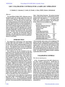
Ð2Ð optical fibres were installed between the PCR and Building 4. Although the line of sight distance is only about 2.5 km, the optical fibres follow the SPS ring via BA2 and BA1 (see Fig. 1) and are routed through patchboards in several surface buildings and the basement of the CERN telephone exchange, resulting in a one-way path length of 6.5 km.
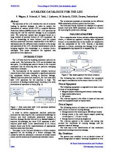
Fig. 1 PCR (28J) Ð Building 4 (25/26J) Round-trip tests with a co-sited transmitter and receiver are necessary in order to allow the jitter of the recovered clock at the receiver to be measured relative to the clock input to the transmitter. They also allow the slow variations in the transmission path delay caused by temperature changes to be observed. With an optical bridge installed at the PCR end, the round-trip B4 Ð PCR Ð B4 distance of 13 km approximately equals the estimated length of the direct fibre link from the PCR to the remotest experiment area (CMS at Point 5), which it is planned to install during the course of 2000. Fig. 2 indicates the results of OTDR measurements on these fibres. In addition to the reflections at the patch points there appears to be a reflection from a minor defect in
Ð3Ð the multimode fibre about 100m after SR1 but this causes negligible attenuation. The non-linearity is due to OTDR receiver saturation by the large reflection from the patch panel at SR1. The RD12 TTC system uses high-power Fabry-Perot lasers operating in multiple longitudinal modes, which are much less disturbed by reflections than DFB types. However, Fig. 2 shows that the connectors and couplings at the patch points introduce an attenuation of several dB, which could be avoided at the expense of flexibility by the use of fusion splices. Including the additional connector and patchcord losses at the PCR, the round-trip attenuations are about 17 dB and 23 dB for the singlemode and multimode fibres respectively. The measurements on multimode fibre using different methods are less consistent than on singlemode fibre because of the dependence of attenuation on optical launch conditions.
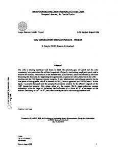
Fig. 2 Fibre OTDR PCR Ð Building 4 Fig. 3 shows the results of tests of the performance of the multimode and singlemode fibres for the transmission of a 40.08 MHz square wave over the 13 km loop. In these tests the signal was received by a low-noise modular optoelectronic receiver since the use of a TTCrx would have masked the effects of fibre dispersion to some degree. The jitter of the received signal was found to be about 11 ps rms over the singlemode fibre and 50 ps rms over the multimode fibre loop. The RD12 system operates at 1310 nm, at which the chromatic dispersion of the fibre is negligible for narrow
Ð4Ð spectrum laser sources, and the relatively low multimode dispersion of the 50/125Êmm fibre indicates a fibre bandwidth exceeding the 2 GHz.km minimum for which it is specified. Multimode fibre has been chosen for the distribution of the TTC signals at the experiments because the dispersion is low over the short distances involved (typically less than 100m). Multimode optical tree couplers, which will be required in large numbers for these networks, are substantially cheaper (by a factor of about three) than equivalent singlemode devices and there is also a certain cost advantage for other distribution components such as optical fibre connectors and coupling bushings.
MMF
SMF
Fig. 3 40.08 MHz bunch clock transmission over 13 km fibre On the other hand for the longer links from the PCR transmitter to the LHC experiment areas these tests indicate that the improved performance of singlemode fibre is significant and since only a single 1x32 optical tree coupler is required at the transmitter its higher cost is less important. It has therefore been decided to design the system for broadcasting the timing signals from the PCR to the experiments with singlemode fibre, while maintaining multimode fibre for the distribution systems at the experiments themselves. CERN already has quite an extensive infrastructure of installed optical fibre, much of it in the form of cables containing a mixture of singlemode and multimode fibres. Because of the fact that the multimode fibres were the first to be taken up, there are at present more singlemode than multimode fibres available for immediate use.
Ð5Ð 4 PCR TTC transmitter The optimum optical input signal level for the present versions of the PIN/Preamp and TTCrx is about -20 dBm. Higher signal levels may cause pulse width distortion, whereas lower signal levels result in higher clock jitter and (although the actual rate is too low to be measured) a greater probability of error. To cope with the 17 dB attenuation of the longest links, the PCR transmitter has been designed to provide multiple outputs at a level of -3 dBm. This has been achieved using an OL364A-40 laser diode with a nominal output at 1310 nm of 40ÊmW (+16ÊdBm), feeding directly a 1x32 singlemode tree coupler with an insertion loss of 19 dB per port (15 dB splitting loss plus 4 dB excess loss). For stable operation and long life the laser temperature is regulated within ±0.1°C by a 3-term controller. The transmitter, which is a singlemode version of an initial development model that has already been supplied to several users, is shown in Fig. 4.
Fig. 4 High power TTC laser transmitter for PCR Many of the shorter optical fibre links from the PCR, such as those to ATLAS, ALICE and the test beam areas in the West and North Halls, will have an attenuation considerably less than 17ÊdB. Small fanout optical tree couplers can be used to split the power available for these links further and so provide additional outputs. Using a new compact laser transmitter module (TTCtx) which is being developed by RD12, an additional 14 outputs at -3 dBm can be provided from the present PCR transmitter crate should the need arise. Additional TTCtx modules can be housed in a second crate should further expansion become necessary at some future date. A maximum of 280 singlemode outputs at -3 dBm could be supplied per crate. The optical power delivered to the main receiver (LHCrx) at each LHC experiment area will be adjusted to the optimum value of -20ÊdBm by inserting fixed optical attenuators of appropriate value. Compact singlemode in-line and build-out attenuators are available from several manufacturers in a suitable range of values.
Ð6Ð The PCR TTC transmitter is complete and has been running satisfactorily in BuildingÊ4. No failures have so far occurred in the multimode versions which were supplied to developers several years ago. With the co-operation of CERN SL/CO and SL/HRF Groups it is planned to install the transmitter in the PCR during the 2000 shutdown as soon as space has been made available in Rack 7407, probably in February. During the shutdown sufficient singlemode fibres will be installed from Rack 7407 to the distribution racks in the PCR transmission room. 24 singlemode fibres are already available in the existing SMF/MMF cable but they need terminating. This can only be done during the shutdown because the multimode fibres are in use for the SPS timing. Because the correct functioning of the PCR transmitter is necessary for the running of all the LHC experiments, a spare unit should be installed at a future date so that a backup is immediately available. There are sufficient outputs to drive duplicate fibre links from the PCR to each LHC experiment area if this redundancy is desired. The transmitter crate incorporates an LHCrx module (described later) which provides facilities for monitoring either the encoded optical output signal or the bunch crossing and orbit clocks extracted from it. The optical fibre to Building 4 will be left in place so that at any time the output from the PCR transmitter can be monitored with the communications signal analyser there for diagnostic purposes. 5 Phase stability The initial set up of the deskew parameters in all the TTCrxs for each subdetector will be done from a database of computed delays and test pulse generator measurements. When LHC beams are available, the timing will be fine tuned by procedures such as crosscorrelation of the event occurrence pattern with the known LHC bunch structure, consecutive signal sample amplitude comparison or possibly online track fitting. These procedures can be implemented in automatic feedback control loops concurrently with normal data-taking. Any slow variation in the phase of the 40.08 MHz clock delivered by the TTC system relative to the actual LHC bunch crossings will thus be automatically compensated for within these control loops. However, it is very desirable that any such phase wander be as small as possible. As a preliminary test of the phase stability of the transmitter and the long distribution fibre from the PCR, measurements were made at intervals during a period of a few days of continuous running via the 13 km loop. A repetitive pattern was observed in which the path delay varied between a minimum in the early morning and a maximum at the end of the afternoon. The total diurnal variation was less than 100 ps and no longer-term drift of the mean was observed. This is a remarkably small variation. The propagation delay temperature coefficient of ordinary (non phase-stabilised) optical fibre is of the order of 10 ppm/°C, or 50 ps per °C for a 1 km length. The small variation observed is attributed to the fact that since the fibre is largely underground only small sections of it are subject to significant diurnal changes in temperature.
Ð7Ð
PREVESSIN CONTROL ROOM
LHC Clock 40.08 MHz
FARADAY CAGE
LHC Orbit 11.246 kHz
ENCODER MODULATOR
LASER +16 dBm 1310 nm 1:32 SM TREE COUPLER
MONITOR
-3 dBm
Singlemode fibres (Max atten 17 dB) Other LHC experiment areas Test beam areas Beam instrumentation Other destinations
-20 dBm
LHC EXPERIMENT AREA
TTCmi Other TTC partitions LVL 1 Cal
LVL 1 Muon
LHC Orbit LHC Clock ENCODER
GLOBAL TRIGGER
L1 Accept
Addressed data Broadcast controls
MODULATOR LASER
TTCvi
VME
SYSTEM CONTROL 1310 nm
1:32 MM TREE COUPLER
OPTICAL DISTRIBUTION BACKBONE ( > 1000 multimode fibres)
ELECTRONICS CONTROLLER
I2C
TTCrx
JTAG Fine and coarse programmable delays
¥ 40.08 MHz clock ¥ Level 1 trigger accept ¥ Bunch counter reset ¥ Bunch crossing number ¥ Event counter reset ¥ Event number ¥ Broadcast commands ¥ Subaddress ¥ Addressed parameters
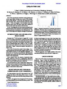
Fig. 5 Overall block diagram of TTC distribution
Ð8Ð 6 Faraday cage link An overall block diagram of the TTC distribution system is shown In Fig. 5. The 40.08 MHz bunch crossing clock, the 11.246 kHz LHC orbit clock and (initially) the 43ÊkHz SPS orbit clock will be delivered to the PCR transmitter in Rack 7407 from the nearby Faraday cage by low-loss coaxial cables. This link is currently being developed by CERN SL/HRF Group and should be installed during the shutdown. This coaxial cable link will run from Faraday cage Rack 9408 and will incorporate galvanic isolation to avoid creating a DC loop between the two buildings. A PLL in the PCR transmitter crate will reduce the jitter of the received 40.08 MHz clock before it is applied to the biphase mark encoder. The LHC and SPS orbit signals will be phased relative to the bunch clock such that they can be qualified by it at the encoder. Provided that it is invariable, the actual phase of the orbit signals relative to the circulating beams is not important as it can be adjusted individually in the LHCrx receivers at each experiment destination throughout a full 360°. The LHC orbit and SPS orbit signals are alternatives which will not be transmitted at the same time. The SPS orbit signal is intended for use only during the period of running with LHC-structured test beams scheduled in May 2000. 7 TTCmi In the initial phase, RD12 developed the components required to broadcast TTC signals to the electronics controllers within a single trigger partition. In this context a partition is defined as a distribution zone which, at least at times, must operate with Level-1 trigger accepts and other broadcast signals which differ from those in other zones. This implies that each partition has its own TTCvi, optical transmitter and fibre distribution network.
Fig. 6 TTCmi A TTC machine interface (TTCmi) is now being developed which will receive the optical timing signals to be broadcast by the TTC transmitter in the PCR and distribute the bunch clock and suitably phased orbit clock to the TTCvi modules and optical TTC transmitters for many such trigger partitions. The complete TTCmi is shown in Fig. 6.
Ð9Ð
DC-coupled ECL O/Ps (Max 2 x 40)
Singlemode fibre from PCR Tx 88.924 ms
LHC ORBIT Max attenuation 17 dB
0-3563 x 25 ns 40.08 MHz CLK GLOBAL ORBIT PHASE
LEVEL
1 ms
-20 dBm LHC ORBIT 1310 nm PIN + PREAMP
READY TTCrx RST
Optional TTCvi
40.08 MHz CLK SW REG
BM ENCODER
80 ps
Tx
Optional encoded optical O/Ps
80.16 MHz OSC
¸2
Optional encoded electrical O/Ps
¯ VCXO 160.32 MHz
¸4
7 ps
LHC ORBIT
PLL
CD MONITOR Rx
40.08 MHz BC Clock (Square wave)
40.08 MHz CLK
Fig. 7 TTCmi block diagram In some (but not all) LHC experiments the main L1A generated by the central trigger processor will, during normal running, be broadcast to all partitions. But the possibility of operating any partition independently with special or test triggers is considered important and this must be provided for in the TTC distribution system.
Ð 10 Ð A simplified block diagram of the TTCmi is shown in Fig. 7. It is based on the TTC minicrate which was supplied to many users during the development phase of the project, with the addition of a new LHCrx module and a variable number of TTC Clocks Fanout modules. The development of the TTCmi has been funded directly by equal contributions from the LHC collaborations and one TTCmi is now being constructed for each experiment. It is also possible to upgrade a TTC transmitter minicrate to a TTCmi. 8 LHCrx The LHCrx replaces the simple Monitor Rx module in the TTC minicrate but it retains the optical signal monitor facility which is useful for diagnostic purposes. It uses a TTCrx ASIC to extract the bunch and orbit clocks from the encoded optical input and provides ECL outputs for further processing. The bunch clock output is an AC-coupled 40.08 MHz square wave while the orbit output is a DC-coupled negative-going pulse train of duration 1 ms and period 88.924 ms. These are the signal characteristics for which the transmitter encoder clock and TTCvi orbit input circuits were designed.
Fig. 8 LHCrx The TTCrx coarse deskew circuit provides for phase adjustment over a range of 16 bunch-crossing intervals (about 400 ns). This is sufficient to compensate for the differences in time-of-flight and optical fibre path length between different destinations at one experiment but not for the phase differences in the orbit signal received from the PCR at different points around the LHC ring.
Ð 11 Ð The LHCrx incorporates a global digital phase adjustment for the orbit signal which allows it to be set throughout the 88.924 ms period in 3564 steps of the bunchcrossing interval of about 25 ns. The master orbit signal phase is set by rotary switches inside the LHCrx which should not require adjustment after being set up for a particular experiment location.
Trace A: Trace B: Trace C: Trace D: Histogram E:
Biphase mark encoded output from PCR transmitter. The central transitions represent the LHC orbit signal, occurring once per 3564 bunch clock periods. 200 ps/div window on bunch clock recovered by the TTCrx Recovered bunch clock after cleanup by PLL in TTCmi 200 ps/div window on Trace C (40.08 MHz bunch clock) Jitter of recovered bunch clock after PLL cleanup. (7 ps rms)
Fig. 9 TTCmi performance (13 km fibre) Owing to the use of a TTCrx ASIC, the 40.08 MHz bunch clock output from the LHCrx has a jitter of about 80 ps rms, which is too high for the master reference for an LHC experiment. This signal is therefore used as the reference phase for a 160.32ÊMHz VCXO/PLL in the TTCmi. The VCXO has very low internal noise, which allows it to be used with a narrow loop bandwidth so that the output jitter is
Ð 12 Ð determined by the sub-harmonic feedthrough from the fundamental oscillator rather than the noise on the reference signal. The ¸ 4 output from the VCXO, which has an rms jitter of about 7 ps, is the master 40.08 MHz clock which drives the TTC distribution system of the experiment. This bunch clock, together with the master orbit clock, is distributed by short coaxial cables to the optical transmitters and TTCvi modules of each of the TTC partitions by TTC Clocks Fanout (TTCcf) modules in the TTCmi. Fig. 9 indicates the performance of the TTCmi when receiving the signal from the PCR transmitter via the 13 km fibre loop. Jitter measurements of the recovered clocks are relative to the clock input to the transmitter, which triggers the analyser. 9 TTCcf In order to choose the configuration of the electrical fanout of the bunch and orbit clocks from the TTCmi, the experiment collaborations were questioned about the number of TTC partitions foreseen. At this time only ATLAS was in a position to provide a preliminary estimate of the partitioning, which is shown in Table 1. Subdetector Pixels SCT TRT EM liquid-argon calorimeter Hadronic end-cap calorimeter Forward calorimeter Tile calorimeter TGC RPC MDT CSC Level-1 calorimeter Level-1 muon Level-2/DAQ
Number of partitions 2 4 4 4 2 2 4 2 2 4 2 1 1 1
Remarks
Barrel right & left, end-cap right & left Barrel right & left, end-cap right & left Barrel right & left, end-cap right & left End-cap right & left End-cap right & left Barrel right & left, extended barrel right & left End-cap right & left Barrel right & left Barrel right & left, end-cap right & left End-cap right & left
Table 1 TTC partitioning in ATLAS The partitioning of the subdetectors is based on the fact that during assembly and testing the subdetectors will be divided into a number of independent parts and for special operations they may be operated with different timing and trigger signals. Partitioning also spreads the load on the TTC network when it is being used to download parameters to the front-end and readout electronics while setting up a physics run. At times it may even be desired to run different parts of a subdetector in different modes (e.g., test mode and calibration mode). The ATLAS model has a total of 35 TTC partitions. To allow some spares the TTCmi was designed to provide over 40 outputs each of the bunch and orbit clocks when it is equipped with 5 TTCcf modules. If more outputs are required as a result of future
Ð 13 Ð expansion, additional modules can be housed in another inexpensive minicrate containing only a -5.2v power supply.
Fig. 10 TTCcf modules Each TTCcf module (see Fig. 10) comprises two independent 1x9 sections, one of which would normally be used for the bunch clock and the other for the orbit clock fanout. In some experiments, such as LHCb, there is a need in the control room to supply more equipment with the bunch clock than the orbit clock. Both sections of each TTCcf have DC-coupled ECL inputs and outputs and they can be used interchangeably for either signal to match such a requirement. TTCcf modules can be configured in a tree structure to reduce the cabling required to supply many destinations from a central point. AC coupling can be used at the bunch clock sources and destinations. For the orbit clock, DC coupling should be maintained from the LHCrx through to each TTCvi since the signal is not balanced and has a low repetition rate. The TTCvi orbit input itself has AC coupling with a DC offset bias. The input capacitor causes considerable signal sag but the following TTCvi circuitry triggers from only the leading edge of the negative-going 1 ms pulse generated by the TTCmi. It is expected that for trigger latency reasons the TTC transmitters for all the partitions will be grouped together in the vicinity of the central trigger processor so that the coaxial cables by which they receive the clock signals from the TTCmi will be short. For longer distances low-loss coaxial must be used with adapters, rather than the miniature solid dielectric type with Lemo 00 connectors.
Ð 14 Ð For even longer distance transmission, or where ground offsets are troublesome, optical transmitters can be plugged directly into the TTCmi crate in place of some of the TTCcf modules. The optical transmitters can be used to send either the 40.08ÊMHz bunch clock alone, or the composite encoded TTC signal, but not the orbit signal alone. The bunch clock can be received with a simple modular optoelectronic receiver, whereas the composite encoded signal requires a TTCrx with PIN/Preamp at the receiving end. 10 TTCtx At the same time as the LHC experiment collaborations were questioned about TTC partition numbers, information was sought about the number of destinations (TTCrxs) per partition which are foreseen. This information would allow the development of a compact laser TTC transmitter module with appropriate optical power output for use in the final systems. In general the collaborations felt that it was still too early to define the requirements precisely, although partition sizes of a few hundred destinations appear most probable. Accordingly it was decided to develop a flexible TTCtx module which can be configured with different numbers and powers of lasers to allow the range 32 to 448 destinations (at the -20 dBm level) to be covered efficiently. For TTC distribution to partitions of 224 or fewer destinations the TTCtx can be operated in two independent halves (i.e., one TTCtx module can serve two partitions of up to 224 destinations each). On the other hand for partitions with more than 448 destinations multiple TTCtxs can be daisy-chained together. A complete crate of TTCtx modules would be able to broadcast to a total of 8960 destinations, divided in from 1 to 40 independent partitions. The ATLAS muon system provides an example of how the proposed partitioning can be matched by TTCtx transmitters. This system will have 3 partitions - one inside the underground electronics cavern and two for the separate halves of the detector. There will be 832 TTCrxs on the detector and 64 in the control room. The control room partition will be driven by one small-configuration TTCtx feeding two 1x32 tree couplers at suitable locations. To reduce the number of fibres traversing the cavern wall, 13 outputs at the -3 dBm level will be run from each of two further TTCtxs to 26 1x32 couplers located around the detector. Each group of 13 couplers will feed the 416 TTCrxs on one half of the detector, which are distributed over the inner and outer octagons in equal numbers of strips of 6 and 7. The design of the TTCtx module has been completed and PCB layout will commence as soon as funding becomes available. 11 LHC-structured test beams During a period of one week in May 2000 it is planned to provide LHC-like structured test beams to the West and North areas. It is foreseen that these special test beams will comprise 2 ms trains of 81 bunches at 25 ns spacing, repeated once every SPS revolution of 23 ms over a slow extraction interval of 2.37 sec. Subdetector development groups from ATLAS, CMS and LHCb plan to exploit this special run.
Ð 15 Ð RD12 will provide the facilities to broadcast the bunch and SPS orbit clocks from the PCR to these experiments. CERN SL/HRF Group successfully carried out first tests of the SPS-LHC rephasing mechanism during a machine development period in September 1999. Rephasing will be implemented before each slow extraction of the structured test beam, allowing the TTC systems to be driven by a continuous 40.08 MHz signal which will remain synchronous with the bunch structure. The SPS 43 kHz orbit signal will be provided for gating purposes. A TTCmi will be provided at each of the test beam facilities. In the case of groups which are already using an RD12 system with a TTC transmitter minicrate, TTCvi and TTCrxs, the TTCmi will be implemented by upgrading the minicrate to a TTCmi with LHCrx and TTCcf modules. The present systems are driven by the local 40.08ÊMHz oscillator in the minicrate. For these groups the only change during the special run will be that the 40.08 MHz clock will be phase locked with the bunch structure of the extracted beam. Several of the diverse DAQ systems in use at the test beams are of older vintage and have quite different timing distribution arrangements from those which will finally be implemented at the LHC experiments. For these systems the TTCmi will just provide electrical outputs of the bunch and orbit clocks for use by the existing electronics. The provisional plans for the H2, H4, H8, X5 and X7 beamlines are as follows. ATLAS will have all the inner detector groups on the H8 beamline in the North Area. A TTCmi will be provided to the SCT Group in Rack RA109, which is also located next to the pixel equipment. It has to be verified that the TRT Group can take the timing signals from there by coaxial cable. CMS plan to exploit the structured beams in both the West and North Areas. The TTC minicrate in use by the Tracker Group on X5 will be upgraded to a TTCmi. The Muon-RPC Group on GIF/X5 will receive the timing signals from the same TTCmi by coaxial cable. In the North Area, a TTCmi will be provided for the HCAL Group on H2. If ECAL and HF Groups will also run on H4 a second TTCmi will be provided for them as it is located quite far from H2. LHCb Vertex and Calorimeter Groups will run on X7 in the West Area. One TTCmi will be provided. ALICE do not intend to run with the structured test beams. 12 Optical tree couplers Fused biconic taper (FBT) fabrication remains the technology of choice for optical tree couplers for TTC distribution networks. Although bare couplers can be integrated in custom detector electronics and used for inter-module distribution
Ð 16 Ð within crates, additional protective packaging is required for mounting them in standard distribution racks.
Fig. 11 1U rack-mounting 1x32 multimode tree coupler In order to experiment with packaging options a number of enclosures for optical tree couplers have been developed. Fig. 11 shows a 1x32 coupler mounted in a 1U rack tray. Industrial cable breakout enclosures of this size generally provide for 24 outputs but the higher density is easily accommodated and better matches standard coupler ratios.
Fig. 12 Cassette-mounted 1x32 singlemode tree coupler Fig. 12 shows the cassette enclosure which was developed for the singlemode 1x32 coupler for the PCR TTC transmitter. Whereas 1x32 multimode couplers can be created in a single fuse, the maximum fanout possible with singlemode fibre is 1x4. Accordingly this 1x32 coupler is formed of a tree composed of eight 1x4 couplers spliced to two intermediate 1x4 couplers fed by one 1x2 coupler at the root. The assembly of such a configuration is quite delicate but the finished packaged coupler is very robust. The total spread in the optical output power delivered by the 32 ports is less than 1.9 dB.
Ð 17 Ð 13 Optical fibre The RD12 system will use singlemode fibre for the distribution of the machine timing signals from the PCR transmitter to the TTCmi in the LHC experiment areas and multimode fibre for TTC distribution at the experiments themselves. Standard 50/125 mm graded index fibre (NA = 0.2, minimum bandwidth 400 MHz.km at 1310Ênm) is suitable for the local multimode installations and for safety reasons sheathing should be LSZH (low smoke zero halogen). Suitable radiation-tolerant fibre is available from at least two vendors. The connectors used for most installations are the industry-standard ST/PC type available from many manufacturers. At present CERN stores do not supply optical fibre, connectors, tooling, or accessories like adapters, couplings, splices and attenuators. For the convenience of developers RD12 requested that ready-connectorised multimode optical patchcords be stocked in lengths of at least 0.5 m ±5%, 5 m ±2% and 50 m ±1%. The 0.5 m patchcord would suit interconnecting modules in the same crate (laser transmitters to optical tree couplers and local monitor receivers, for example). The 5Êm length would cover general lab interconnections and links between modules in different crates in adjacent racks, while the 50 m length (used singly or in pairs for 100 m) would allow users to test over the distances that will be required for optical signal distribution at the LHC experiments. The standardisation request is still being processed. Until such time as these patchcords are available, users who do not wish to buy their own connector tooling can have patchcords assembled by local service vendors. They are not provided by RD12, although we will consider stocking them in the future if the request to CERN stores is not accepted and funds are available. 14 TTCvi To date a total of 40 TTCvi modules [4,5] have been produced, of which 19 have been supplied to ATLAS and 15 to CMS. Support has been provided to the users, who are generally very satisfied with the modules and have integrated them in their TTC systems without many problems. Only one faulty module (out of the first production batch) was returned. In October 1999 a questionnaire was distributed to about 60 users soliciting comments and suggestions for improvements which might be incorporated in a future production batch. 6 replies were received, including the following proposed modifications: Option to count orbits instead of events (for ALICE) Oscilloscope monitor outputs on the A and B channels Additional B-Go channels Longer duration counter Clock source (int/ext) readable from VME Read back of FIFO content
Ð 18 Ð Event counter with D32 VME access Setting subaddress of Event Count/Trigger Type from VME These proposals will be taken into account for the next production batch of TTCvi modules and funding has been requested for the required development and PCB layout work. 15 ALICE requirements The TTCvi modifications requested by ALICE result from fundamental differences in the trigger and readout of the subdetectors of that experiment. Some of the ALICE subdetectors also have particularly stringent requirements on timing precision. The Birmingham ALICE group obtained a TTC transmitter minicrate, TTCvi and (old version) TTCrx test board at the beginning of 1999. The system has been successfully operated in the lab, and software is being developed to broadcast messages and perform read-out cycles obtaining event numbers and other similar tasks. The trigger-detector protocol has been re-examined during the year, resulting in a better understanding of how the TTC system is to be used in trigger distribution. The ALICE trigger has three levels: L0 (delivered to the detector front-end in less than 1.2Êms), L1 (also of fixed latency at around 5.5 ms) and L2 at the end of the TPC drift time (currently 88 ms). The RD12 TTC system will be used to deliver L1 and to distribute event identifiers. Unlike ATLAS and CMS, where in general all subdetectors contribute to a given event, it is a feature of the ALICE detector readout that the sets of detectors required for successive events are in general different. This is because the readout cycles for the detectors take widely differing times, so restricting all to the slowest readout would lead to an unacceptable reduction in event rate. This requirement complicates the event numbering in ALICE, as it means that event numbers in a given subdetector will not necessarily be sequential. In order to cope with this, the choice was made to use bunch crossing number and orbit number as event identifiers, as these should be the same for every subdetector. The orbit number is not currently transmitted. A solution is being explored whereby the TTCvi module could be reconfigured to transmit orbit number rather than event number. This involves essentially a reprogramming of an FPGA. As detector groups set about preparing their electronics, demand is growing for TTC components for tests. For this purpose, ALICE is acquiring a number of TTCvx modules and TTCrx ASICs which will be made available to detector groups for development work. The precise timing distribution offered by the TTC system will be particularly essential for two detectors: the Time-of-Flight (TOF) and Forward Multiplicity Detectors (FMD). The details of the electronics chain are not yet finalised, but test results for the detectors have shown a timing resolution of around 50 ps (TOF) and 75Êps (FMD), indicating that both detectors will require precise timing for their electronics in due course. The TOF system is now to be built using RPCs, while
Ð 19 Ð several options remain open for the FMD. The results quoted are for Microchannel Plate (MCP) detectors. 16 TTCvx As the initial production of 30 TTCvx modules has almost all been delivered to developers a new batch of 20 is being produced. 13 modules have been supplied to ATLAS and 14 to CMS. Modules for the production testing of the TTCvx have been made which provide test signals and allow the optical and LVDS outputs to be monitored. In addition to its use as a development tool, the TTCvx can be used as an encoder for higher power laser transmitters in applications which do not have stringent requirements on clock jitter. (The TTCvx uses a low-cost MPC991 integrated PLL clock driver with ±50 ps cycle-to-cycle jitter). Since the TTCvx PLL has a wideband oscillator the module must be driven by a lowjitter reference clock. In the final LHC experiment configurations, a single VCXO/PLL in the TTCmi provides the cleanup of the received 40.08 MHz bunch clock for all the encoders in the system so that this expensive item is not required in the individual TTC transmitters. A Technical Description and Users Manual [6] for the TTCvx is available and support has been given to the users, who are generally very satisfied with the modules. 17 TTCrx The design of the rad-hard version of the TTCrx ASIC (TTCrx-D) has been completed using DMILL 0.8 mm BiCMOS-SOI technology. Some critical functional elements of the ASIC (postamplifier and PLL) had previously been successfully implemented in that technology for test purposes. The new design was submitted to the foundry at the beginning of September 1999 and 20 samples, including a few packaged in ceramic PGA, are expected back from the manufacturer by the end of January 2000. It was agreed with IMEC that CERN could purchase an extra set of 40 chips if the first samples prove satisfactory. All the remaining chips will then be sent to IBM Semea for BGA packaging and should be returned by the end of April 2000. 10 samples will be retained by CERN EP/MIC Group for evaluation and irradiation tests and the remainder will be distributed to the LHC experiments pro rata with their funding contributions. The new design incorporates several functional differences from the previous 1 mm ES2 design. The following modifications were implemented in response to new user requirements: Internal registers can be accessed via an I2C Bus for read and/or write operations.
Ð 20 Ð Broadcast strobe signal 2 can be synchronised to either clock phase 1 or clock phase 2. Command decoding can be completely switched off in order to use the TTCrx as a simple serial receiver. In order to fight problems caused by radiation-induced single event upsets (SEU) the following functions have been implemented: A watchdog circuit has been added to the ASIC. It constantly monitors the correct operation of the circuit and performs an automatic reset if a loss of synchronisation with the incoming signal is detected. A Hamming correction state machine constantly monitors the internal registers and corrects their contents if an SEU is detected. The most important configuration register bits have been doubled to provide redundancy. The TTCrx Reference Manual [7] has been updated to reflect these changes. At present 78 of the original BGA-packaged CMOS 1 mm ES2 chips (TTCrx-E) remain to be distributed. Of these, 8 will be retained by EP/MIC, 10 will be used for TTCmi LHCrx modules, and 60 will be allocated to the LHC experiments. The allocations within the experiment collaborations will be made by their electronics coordinators. This 1 mm fabrication process is no longer available. Should a shortage of TTCrx ASICs develop before TTCrx-D is in production it could be alleviated by packaging the chips (TTCrx-A) produced in an earlier AMS 0.8Êmm MPW run which was made as part of the design development activity. This version has been tested and the chips could be packaged in PGA-100. The functional differences between the TTCrx-A and TTCrx-D designs have been documented in detail [8]. As TTCrx-A has no watchdog circuit it loses lock if the input signal is interrupted and a reset command cannot be sent from the I2C Bus or via the optical link. The master mode bits do not exist and the register file structure and deskewing conversion formulae are somewhat different. 18 TTCrx for ATLAS The use of the RD12 TTC system in ATLAS has been specified in some detail in the Level-1 Trigger TDR [9]. Several ATLAS subdetector groups have been using the TTC system in laboratory setups and test beams. As a result of this experience additional TTCrx functionality was requested and has been incorporated in the TTCrx-D design. For example, to facilitate timing scans with test pulses it was found useful to be able to synchronize commands and L1A output with different deskewed clocks. Owing to the configuration and construction schedule of the ATLAS tile calorimeter the electronics for this subdetector must be produced during 2000. The DMILL
Ð 21 Ð version of the TTCrx is required for this radiation environment. Hence irradiation testing of the TTCrx-D will be carried out as soon as samples are available and if the results are satisfactory a full engineering run will be launched without delay. TTCrx-D ASICs will also be required for two front-end crates of the liquid argon calorimeter which should be produced and validated during 2001. Irradiation testing of optoelectronic receivers or PIN/Preamps for these applications will be carried out by RD49 as these are COTS components. 19 TTC in LHCb In the last year LHCb has made considerable progress in its plans [10] for the use of the TTC system in the experiment. At present 4 prototype modules equipped with TTCrx evaluation boards are in use for the vertex detector and the inner tracker. It is planned that all the subdetectors will use the RD12 TTC system and 20 boards using TTCrx-D will be produced in 2000. In the LHCb implementation the A Channel will be used for broadcasting the Level0 trigger accept to the front-end electronics. Short-format B Channel broadcast commands will be used to accept or reject the events accepted by L0. These commands will also transmit trigger type information, which informs the front-end whether zero-suppression should be performed, and an event identification to detect single event and most multiple event losses. The event counter reset signal, which will be originated by the DCS system or the readout supervisor, will be used in LHCb as a fast reset for the whole front-end system. Hence all local event counters must roll over at the same count without an event counter reset being generated. During 2000, LHCb will start the development of a readout supervisor which will be the heart of the Timing and Fast Control (TFC) system [11] of the experiment. For partitioning the TFC system a TTC switch will also be designed which will allow the A and B channel information for the TTC transmitters to be associated with selected input ports. The final system is expected to have about 9 TTCtx and 2000 TTCrx. 20 Synchronization RD12 has continued to contribute to the work on the synchronisation of the CMS calorimeter trigger. Based on the experience with the Sync_Rx and Sync_Tx circuits [12] a new design has been produced which integrates the two circuits and the RAM accumulator for bunch profile histogramming in a single XILINX XC4020-XL [13]. The new Sync circuit includes BIST functionality compliant with the Boundary Scan standard IEEE 1149.1. [14] The synchronization circuit was used to implement the interface (Synchronization and Link Board) between the ECAL readout system and the regional trigger system, which is responsible for the synchronization, alignment and transmission of the trigger primitives data [15]. A test system was developed which integrates the SLB prototypes with the TTC system components. The test setup has been running successfully since September 1999.
Ð 22 Ð The general approach to setting up the timing and monitoring the synchronization of the CMS detector has been discussed in the November 1998 CMS Synchronization Workshop and in the June 1999 Front-End, Readout Unit and Synchronization Workshop [16,17]. 21 LHC beam instrumentation The Beam Synchronous Timing (BST) system at present used for LEP beam instrumentation will require replacement or a major and expensive upgrade to meet the needs of the LHC. During the presentation of the TTC system to the Timing Working Group it was suggested [18] that the RD12 laser transmitter to be installed in the PCR in February 2000 might also meet the needs of the CERN SL/BI group for the distribution of LHC bunch and orbit clocks and synchronous commands to the beam instrumentation around the ring. For the beam instrumentation the machine timing signals must be broadcast from the PCR to 24 points around the ring; the 8 access points plus 16 alcoves. There will be about 54 front-end equipment crates and 27 beam instrumentation control crates in each of the 8 arcs of the LHC. The use of optical fibre for the final sections of the links inside the tunnel raises radiation hardness concerns. It is possible that optical fibre installed in the tunnel drain would be sufficiently shielded and studies are being made to confirm this. The timing precision offered by the RD12 system is more than adequate for this application [19] and the TTC transmitter has sufficient outputs for the number of beam instrumentation destinations currently foreseen. By the addition of the new TTCtx module which is under development this number could be expanded by 14 outputs (at the -3 dBm level) in the present crate or by up to 280 such outputs per additional crate installed. The use of the RD12 TTC system in place of the present BST system would require the porting of a large amount of software from the old to the new equipment. The implications of this are being studied by SL/BI Group and if the work appears feasible first tests will be made during 2000. Apart from the cost saving there are evident operational and maintenance advantages in having a single CERN-wide system for the distribution of the same timing signals. 22 Laser safety Safety is an important concern in a system which incorporates a number of laser sources of invisible radiation. The RD12 TTC system is a fibre optic one with no collimated-beam lasers, intended for operation in a Òrestricted accessÓ location [20] with no unsupervised public access. The final distribution fibre ends are connectorised and there is no physical impediment to someone disconnecting one and putting it to their eye while a transmitter is active. However, these links operate at about -20 dBm at 1310 nm and so are well below IEC 60825 Class 1 limits for this wavelength. The transmitters themselves for large partitions can have embedded Class 3A or even lower-band 3B lasers, so these should be in a Òcontrolled accessÓ location like a locked rack from which all accessible emission limits (AEL) are Class 1. All lasers
Ð 23 Ð are pigtailed and housed in modules which can only be accessed with tools. All the outputs from the new TTCtx module will be within the upper limit for Class 1. For the entire divergent light output of a fibre end to be collected by the pupil of the eye it must be held well within the eyeÕs near point, when it cannot be focused sharply on the retina. Viewing with optical aids must be expressly forbidden. Since the higher power transmitters will be quite few in number it should be straightforward to restrict access to them and in particular prevent any unauthorised dismantling of the units with power on. While the possibility of such foolhardy intrusion is extremely remote, to provide multiple lines of defence the full panoply of safety measures can be implemented as per IS 22 [21]. In particular there should be a rack door power interlock, key switches, emergency stop, warning signs and emission indicators. Since every one of these measures can be defeated by a determined person with wire, tools and time, the ultimate barrier is education and access should not be permitted to anyone who is not aware of the potential hazard. 23 TTC mailing list A mailing list has been set up for TTC news and information-sharing among developers and users at CERN and collaborating institutes. All the non-industrial RD12 participants are subscribed to the list and are invited to respond to queries relevant to their areas of interest. To join the mailing list send an email to
[email protected] containing the line: subscribe lhc-exp-ttc To subscribe from another account: subscribe lhc-exp-ttc [your email address] Once registered, one can post TTC comments to the list by sending them to:
[email protected] Questions about the list or requests for assistance should be sent to:
[email protected] 24 Conclusion During 1999 the RD12 Project has progressed further in its endeavour to create common TTC backbone distribution systems for the LHC experiments. Systems developers, electronics and microelectronics designers have continued to co-operate productively with machine specialists, industrial partners and representatives of the experiment collaborations at CERN and external institutes. The Project is well on schedule to deliver appropriate technologies for a CERN-wide solution to the problem of TTC distribution in the timeframe required for the startup of the LHC experiments in 2005. By its nature a written report on an ongoing development activity is outdated when it has been printed and distributed. For regularly-updated information on the status of the project and future plans an RD12 website is maintained at http://www.cern.ch/TTC/intro.html.
Ð 24 Ð 25 Acknowledgment RD12 would like to acknowledge the excellent cooperation and support received from members of CERN SL Division. In particular the contributions of G. Beetham, L.K. de Jonge and O. Olsen of SL/CO Group, Ph. Baudrenghien of SL/HRF Group and J.-J. Savioz of SL/BI Group have been invaluable to the project. References [1]
Taylor, B.G., ÒTTC Distribution for LHC DetectorsÓ, IEEE Trans. Nuclear Science, Vol. 45, June 1998, pp. 821-828.
[2]
Status Report on the RD-12 Project, CERN/LHCC 97-29, 30 April 1997.
[3] [4]
Status Report on the RD-12 Project, CERN/LHCC 98-38, 19 October 1998. Farthouat, P. and GŠllnš, P., ÒTTC-VMEbus Interface (TTCvi)Ó, RD12 working document, CERN.
[5]
GŠllnš, P., ÒModules development for the TTC systemÓ, Proc. 5th Workshop on Electronics for LHC Experiments, Snowmass, Colorado, Sept 1999, pp. 327-330.
[6]
GŠllnš, P., ÒTTCvx: Technical description and users manualÓ, RD12 working document, CERN.
[7]
Christiansen, J., Marchioro, A. and Moreira, P., ÒTTCrx Reference Manual - A Timing, Trigger and Control Distribution Receiver ASIC for LHC DetectorsÓ, RD12 working document, CERN.
[8]
Toifl, T., ÒDifferences between TTCrx-A (AMS) and TTCrx-D (DMILL)Ó, RD12 working document, CERN.
[9]
ÒATLAS Level-1 Trigger Technical Design ReportÓ, CERN, 24 June 1998.
[10] Christiansen, J., ÒUse of TTC system in LHCbÓ, http://lhcb.cern.ch/electronics/html/ ttc_use.htm [11] Jost, B., ÒTiming and Fast ControlÓ, LHCb Technical Note, LHCb DAQ 99-001, 26 Jan 1999. [12] Silva, J.C. and Varela, J., ÒSpecifications of the Prototype Trigger Synchronization Tx/Rx CircuitsÓ, CMS Internal Report, CMS IN 1997/009, CERN. [13] Silva, J.C. and Varela, J., ÒSpecifications of the Calorimeter Trigger Synchronization Circuit, Version 2.2Ó, CMS Internal Report to be published, CERN. [14] Almeida, C.B., Augusto, J., Cardoso, N., Santos, M., Teixeira, I.C., Teixeira, J.P., and Varela, J., ÒTestability Issues in the CMS ECAL Upper-Level Readout and Trigger SystemÓ, Proc. 5th Workshop on Electronics for LHC Experiments, Snowmass, Colorado, Sept 1999, pp. 361-365. [15] Silva, J.C. and Varela, J., ÒTechnical specifications of the ECAL trigger Synchronization and Link Board prototypeÓ, CMS Internal Report to be published, CERN. [16] Smith, W., ÒCMS Synchronization Workshop ConclusionsÓ, CMS Internal Report, CMS IN 1999/016, CERN. [17] Varela, J., et al., ÒSynchronization of the ECAL dataÓ, CMS Internal Report to be published, CERN. [18] Beetham, G., Minutes of the 10th Timing Working Group Meeting (TimWG), 24 Sept 1999, CERN. [19] Savioz, J.-J., Private communication. [20] ÒSafety of laser products - Part 2: Safety of optical fibre communications systemsÓ, IEC 60825-2, 1993-09. [21] ÒRules for the Safe Use of Lasers at CERNÓ, CERN TIS/RP Safety Instruction IS22 Rev., Jan 1994.