advertising or promotional purposes or for creating new collective works for ... Index TermsâFinite-element method, MachâZehnder inter- ferometer, optical Kerr ...
Title
Author(s)
Citation
Issue Date
Doc URL
Finite-element modeling of nonlinear Mach-Zehnder interferometers based on photonic-crystal waveguides for alloptical signal processing Fujisawa, T.; Koshiba, M.
Journal of Lightwave Technology, 24(1): 617-623
2006-01
http://hdl.handle.net/2115/5777
Right
©2006 IEEE. Personal use of this material is permitted. However, permission to reprint/republish this material for advertising or promotional purposes or for creating new collective works for resale or redistribution to servers or lists, or to reuse any copyrighted component of this work in other works must be obtained from the IEEE. IEEE, Journal Of Lightwave Technology , vol.24(1), 2006, p617-623
Type
article
Additional Information
Hokkaido University Collection of Scholarly and Academic Papers : HUSCAP
Instructions for use
Hokkaido University Collection of Scholarly and Academic Papers : HUSCAP
JOURNAL OF LIGHTWAVE TECHNOLOGY, VOL. 24, NO. 1, JANUARY 2006
617
Finite-Element Modeling of Nonlinear Mach–Zehnder Interferometers Based on Photonic-Crystal Waveguides for All-Optical Signal Processing Takeshi Fujisawa, Member, IEEE, and Masanori Koshiba, Fellow, IEEE, Fellow, OSA
Abstract—A nonlinear Mach–Zehnder interformeter based on photonic-crystal waveguides is proposed and modeled by using rigorous finite-element-based numerical scheme. Guided modes of nonlinear photonic-crystal waveguides are investigated to determine a length of nonlinear arm and a switching power, and further, intensity-dependent switching characteristics of the nonlinear Mach–Zehnder interferometer, for the first time, as far as the authors know, are demonstrated. Effects of saturable nonlinearity and two-photon absorption (TPA) on switching characteristics are also taken into account. Index Terms—Finite-element method, Mach–Zehnder interferometer, optical Kerr effect, photonic-crystal waveguide, twophoton absorption.
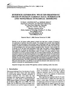
Fig. 1. Nonlinear Mach–Zehnder interferometer.
and further, intensity-dependent switching characteristics of the nonlinear Mach–Zehnder interferometer, for the first time, to our knowledge, are demonstrated. Effects of saturable nonlinearity and two-photon absorption (TPA) on switching characteristics are also taken into account.
I. I NTRODUCTION
P
HOTONIC CRYSTALs (PCs) have inspired great interest because of their potential abilities to control lightwave propagation and to realize ultrasmall optical devices [1], [2]. In recent years, not only linear optical devices, but also nonlinear optical devices based on PCs using the optical Kerr effect, have been suggested for all-optical signal processing [3]–[8]. A Mach–Zehnder interferometer is one of the most important components in integrated optical circuits and has been utilized for extensive optical devices such as switches, modulators, and so on. Recently, a Mach–Zehnder interferometer based on PC waveguides has been suggested [3], [9]–[12]. In order to control the optical output, the extra phase shifts are added to one of its arms, for example, by changing the refractive index [3], by changing the optical-path length [9], [10], by thermooptic effect [11], and by using liquid crystals [12]. The nonlinear Mach–Zehnder interferometer using the optical Kerr effect seems to be more suitable for faster transmission systems because of its ultrafast response; the PC-based nonlinear Mach–Zehnder interferometer has also been suggested [3]. In this paper, the nonlinear Mach–Zehnder interferometer based on PC waveguides is proposed and modeled by using rigorous finite-element-based numerical scheme. Guided modes of nonlinear photonic-crystal waveguides are investigated to determine a length of nonlinear arm and a switching power, Manuscript received September 9, 2004; revised May 17, 2005. The authors are with Division of Media and Network Technologies, Graduate School of Information Science and Technology, Hokkaido University, Sapporo, Hokkaido 060-8628, Japan. Digital Object Identifier 10.1109/JLT.2005.860143
II. G UIDED M ODE A NALYSIS OF N ONLINEAR P HOTONIC -C RYSTAL W AVEGUIDES A. PC Waveguides of Square Lattice In the nonlinear Mach–Zehnder interferometer, one of the arms is replaced by a nonlinear optical waveguide as shown in Fig. 1. The optical output of the nonlinear Mach–Zehnder interferometer is modulated by the phase difference between the linear and nonlinear arms caused by the optical Kerr effect. To determine the length of nonlinear arms and the switching power, the guided mode analysis of the nonlinear waveguide is essential. One-dimensional (1-D) finite-element method (FEM) has been widely used for the guided mode analysis of nonlinear slab waveguides [13]. On the other hand, for the periodic optical waveguide such as PC waveguides, 1-D FEM is no longer valid, because the structure varies along the propagation direction. Then, FEM for the nonlinear periodic optical waveguides [14] is used for the guided mode analysis of nonlinear PC waveguides. Generally speaking, there are two types of lattice structures and two types of configurations to form PC waveguides. With regard to lattice structures, PC is usually based on square or triangular lattice structures, and both structures have some advantages and disadvantages. Although triangular lattice structures have advantages such as large photonic band gap (PBG), there are also disadvantages; for example, the transmission characteristics of waveguide bends, which are important in integrated photonics, are not so good. For square lattice structures, they do not have a large PBG compared with those of triangular
0733-8724/$20.00 © 2006 IEEE
618
JOURNAL OF LIGHTWAVE TECHNOLOGY, VOL. 24, NO. 1, JANUARY 2006
Fig. 2. (a) Elementary cell of a PC waveguide of square lattice with nonlinear materials (black regions) and (b) the dispersion curve for b = 0.3a.
lattice structures; however, the transmission characteristics of waveguide bends are excellent. With regard to configurations of PC, there are so-called rod-type and air-hole-type structures. Air-hole-type structures are much easier to fabricate than rodtype structures. However, a frequency bandwidth of the singlemode region in air-hole-type waveguides is limited because of the existence of higher order modes. PC waveguides based on rod-type structures have some advantages compared with air-hole-type waveguides, because the large bandwidth of the single-mode region and the large group velocity can be easily obtained, and, recently, such waveguides have been fabricated and PBG guidance have been confirmed [15]–[17]. Therefore, in this paper, rod-type PC waveguides of square and triangular lattice structures are treated. Full three-dimensional (3-D) simulations are necessary for PC waveguides to evaluate various effects such as out-ofplane radiation. However, to the best of our knowledge, there have been no reports about full 3-D simulations of “nonlinear” PC circuits so far, probably because of much computational resources required for simulations. We believe that it is very important and useful for many researchers to show characteristics of two-dimensional (2-D) nonlinear PC devices before full 3-D simulations are started, because we can see general characteristics of 3-D PC devices from the 2-D results. Therefore,
Fig. 3. (a) Nonlinear phase shifts, (b) relative waveguide length necessary for π-phase shift as a function of n2 P , and (c) relative waveguide length necessary for π-phase shift as a function of n2 P for different values of a/λ.
2-D nonlinear PC waveguides are intensively investigated in this paper. Here, we consider a nonlinear PC waveguide composed of dielectric pillars (rods) on square array with lattice constant a = 0.4 µm, as shown in Fig. 2(a), where the diameter and the linear part of the refractive index of rods are, respectively, taken as d = 0.5a and nL = 3.5, and the refractive index of the background material is assumed to be 1.5. Light can be confined in the vertical direction (x-direction), because the background
FUJISAWA AND KOSHIBA: FINITE-ELEMENT MODELING OF NONLINEAR MACH–ZEHNDER INTERFEROMETERS
Fig. 4. (a) Elementary cell of a PC waveguide of triangular lattice with nonlinear materials (black regions) and (b) the dispersion curve for b = 0.3a.
material is not air, resulting in low out-of-plane losses. Inplane losses can be suppressed by adding a lot of layers in the cladding region, and in this case, seven layers in the cladding region are enough to confine light in the core region. This PC has a PBG for TE modes that extends from a/λ = 0.24 to 0.29, with λ being the free-space wavelength [3]. The waveguide is formed by reducing the diameter of a row of rods to b. Only the rods of diameter b have the nonlinear refractive index n given as � n = nL
n2 |E|2 1+ Z0
� 12
for nonsaturable nonlinearity and � � �� nL n2 |E|2 n = nL + ∆nsat 1 − exp − 2∆nsat Z0
(1)
(2)
for saturable nonlinearity, where n2 is the nonlinear coefficient, ∆nsat is the saturation of nonlinearity, Z0 is the free-space impedance, and E is the electric field distributions. This waveguide structure is expected to enhance the nonlinearity [14]. Fig. 2(b) shows the dispersion curve for b = 0.3a. This waveguide is single moded in the PBG. Fig. 3(a) shows nonlinear phase shifts per unit length ∆ϕ, defined as � � L (3) ∆ϕ = k0 nNL eff − neff
619
Fig. 5. (a) Nonlinear phase shifts and (b) relative waveguide length necessary for π-phase shift as a function of n2 P .
for the PC waveguides with and without saturable nonlinearity as a function of n2 P , where a/λ = 0.263, which is almost the center frequency of PBG. Here, nLeff and nNL eff are the linear and the nonlinear effective refractive indexes, respectively, and P is the optical power. Nonlinear phase shifts are enhanced for larger values of n2 P . We can see that ∆ϕ saturates for larger values of n2 P when saturable nonlinearity is considered. Fig. 3(b) shows the relative waveguide length necessary for π-phase shift as a function of n2 P , which is derived by L = π/∆ϕ. For saturable nonlinearity, a larger value of n2 P is required to obtain π-phase shift for the same waveguide length. Fig. 3(c) shows the relative waveguide length necessary for π-phase shift without saturable nonlinearity for different values of a/λ. The values of a/λ = 0.26473 and 0.261267 correspond to ±10 nm changes from the wavelength expressed as a/λ = 0.263. The nonlinearity is enhanced for shorter wavelength because of the strong confinement of light. B. PC Waveguides of Triangular Lattice Here, we consider a PC waveguide of triangular lattice with lattice constant a = 0.4 µm, as shown in Fig. 4(a). The linear part of the refractive index of rods and the refractive index of background material are taken as 3.5 and 1.5, respectively, and the diameter of rods is d = 0.5a. This PC has a PBG for
620
JOURNAL OF LIGHTWAVE TECHNOLOGY, VOL. 24, NO. 1, JANUARY 2006
Fig. 6. Nonlinear Mach–Zehnder interferometers based on PC waveguides of (a) square lattice and (b) triangular lattice.
TE modes that extends from a/λ = 0.235 to 0.315. Fig. 4(b) shows the dispersion curve for b = 0.3a. This waveguide is single moded in the PBG. Fig. 5(a) and (b) shows nonlinear phase shifts, and the relative waveguide length necessary for π-phase shift with and without saturable nonlinearity as a function of n2 P , where a/λ = 0.2529. This frequency is almost the center frequency of the guided band of this waveguide. For the saturable case, the nonlinearity is weaker than that for the nonsaturable one. III. N ONLINEAR M ACH –Z EHNDER I NTERFEROMETERS A. PC Mach–Zehnder Interferometers of Square Lattice In this section, we consider a nonlinear Mach–Zehnder interferometer based on PC waveguides as shown in Fig. 6(a). All the parameters related to PCs are the same as in Section II-A, and b is taken as 0.3a. The Mach–Zehnder interferometer considered here is composed of four input/output ports and two couplers whose coupling length is Lc = 15a. Nonlinear defect rods are placed in one of the arms [black ones in Fig. 6(a)], and their nonlinear refractive indexes are given by (1) or (2). The length of the nonlinear arm is assumed to be L = 130a. Switching characteristics of this nonlinear PC Mach–Zehnder interferometer are evaluated by using frequency-domain FEM [18], which is applied to the whole structure. Fig. 7(a) shows the normalized output powers in ports 3 and 4 as a function of n2 P for a/λ = 0.263, where nonsaturable nonlinearity is considered. At this frequency, the two couplers are operated as a 3-dB power divider, and the signal inputted to port 1 is transmitted to port 3 in the linear regime. We can see that the output signal is switched from port 3 to port 4 for larger values of n2 P . The dashed line shown in Fig. 7(a) is the value of n2 P required for switching estimated by the guided mode analysis [white circle in Fig. 3(b)]. Although
Fig. 7. Nonlinear output powers in ports 3 and 4 as a function of n2 P where (a) nonsaturable nonlinearity and (b) saturable nonlinearity are considered.
the switching power obtained by the guided mode analysis is in good agreement with that calculated by the frequencydomain FEM, we can see a slight inconsistency between the two results. Since only one unit cell is treated in the guided mode analysis as shown in Fig. 2(a), effects of waveguide bends and coupling elements are not taken into account in the guided mode analysis. Thus, we think that the inconsistency is attributed to the effects of waveguide bends and coupling
FUJISAWA AND KOSHIBA: FINITE-ELEMENT MODELING OF NONLINEAR MACH–ZEHNDER INTERFEROMETERS
621
Fig. 9. Normalized output powers in port 4 as a function of n2 P for different values of a/λ.
Fig. 10. Normalized output powers in ports 3 and 4 as a function of n2 P .
Fig. 8. Field distributions of the nonlinear PC Mach–Zehnder interferometer for (a) linear, (b) n2 P = 1.26 nm, and (c) n2 P = 2.2 nm.
elements. It should be noted that almost no signal is outputted in ports 1 and 2, corresponding to the reflected power, although those are not shown here. Fig. 7(b) shows the normalized output powers in ports 3 and 4 as a function of n2 P for a/λ = 0.263, where saturable nonlinearity is considered. For ∆nsat = 0.01, the output power is saturated before complete switching, and longer arm length is required to obtain π-phase shift. For ∆nsat = 0.04, on the other hand, complete switching is achieved around n2 P = 4.4 nm. The switching power is almost twice compared with the nonsaturable nonlinearity case, and this power
is coincident with that obtained by the guided mode analysis [black circle in Fig. 3(b) and dashed line in Fig. 7(b)]. Fig. 8(a)–(c) shows the field distributions of the nonlinear PC Mach–Zehnder interferometer for the linear, n2 P = 1.26 nm and n2 P = 2.2 nm, respectively. We can see that all-optical switching operation could be performed. If we take AlGaAs below half the electronic band gap as a nonlinear material whose nonlinear coefficient is n2 = 1.5 × 10⁻¹⁷ m2 /W [7], the optical power P is on the order of tens of watts per micrometer for n2 P = 1 nm. A peak intensity level of ∼ 10 W/µm corresponds roughly to 10 GW/cm2 that is frequently used in experimental works [19], [20], and this power can be further reduced by changing the length of the nonlinear arm as shown in Fig. 3(b). In Fig. 9, normalized output powers in port 4 as a function of n2 P for different values of a/λ are shown where nonsaturable nonlinearity is considered. When a/λ is detuned to shorter wavelength, the switching characteristic is almost the same. On the other hand, when a/λ is detuned to a longer wavelength, the switching characteristic is degraded. This degradation is mainly caused by the change of power ratio split by PC couplers. Finally, we consider the effect of TPA on switching characteristics of the nonlinear Mach–Zehnder interferometer. If TPA is taken into account, the refractive index of nonlinear rods is given as [21] � � n2 nL α −j (4) |E|2 n = nL + nL 2Z0 4Z0 k0 where α (in meters per watt) is the TPA coefficient and k0 is the free-space wavenumber. Fig. 10 shows the normalized
622
JOURNAL OF LIGHTWAVE TECHNOLOGY, VOL. 24, NO. 1, JANUARY 2006
Fig. 11(a)–(c) shows the normalized output powers in ports 1–4 as a function of n2 P , where nonsaturable nonlinearity, saturable nonlinearity, and TPA are considered, respectively, for a/λ = 0.2529. The light is inputted to port 1, and most of the light is transmitted to port 3 for the linear case. The output signal is switched from port 3 to port 4 for larger values of n2 P . Unlike the square lattice case, there are reflections in ports 1 and 2 because of the waveguide bend. Optimized waveguide bends are required to achieve better switching characteristics in the triangular lattice case. IV. C ONCLUSION The nonlinear Mach–Zehnder interferometer based on PC waveguides was proposed and modeled by using rigorous finite-element-based numerical scheme. Guided modes of nonlinear PC waveguides were investigated to determine the length of nonlinear arm and the switching power, and further, intensity-dependent switching characteristics of the nonlinear Mach–Zehnder interferometer were demonstrated. Effects of the saturable nonlinearity and TPA on switching characteristics were also presented. R EFERENCES
Fig. 11. Normalized output powers in ports 1–4 as a function of n2 P where (a) nonsaturable nonlinearity, (b) saturable nonlinearity, and (c) TPA are considered.
output powers in ports 3 and 4 as a function of n2 P , where TPA effect is taken into account. We can see that for αP = 0.0001, the extinction ratio is degraded, compared with the case of neglecting the TPA effect and that the TPA effect becomes more serious for larger values of P . B. PC Mach–Zehnder Interferometers of Triangular Lattice Here, we consider a nonlinear Mach–Zehnder interferometer based on PC waveguides of triangular lattice, as shown in Fig. 6(b). All the parameter related to PCs are the same as in Section II-B, and b is taken as 0.3a. The structure of the Mach–Zehnder interferometer is similar to the square lattice case. In this case, the coupling length of coupler is Lc = 20a, and the length of nonlinear arm is assumed to be L = 100a. For waveguide bend, the 120◦ bend is employed, because it is difficult to use the 90◦ bend in the PC of triangular lattice.
[1] J. D. Joannopoulos, P. R. Villeneuve, and S. Fan, “Photonic crystals: Putting a new twist on light,” Nature, vol. 386, no. 6621, pp. 143–149, Mar. 1997. [2] M. Koshiba, “Wavelength division multiplexing and demultiplexing with photonic crystal waveguide couplers,” J. Lightw. Technol., vol. 19, no. 12, pp. 1970–1975, Dec. 2001. [3] M. Solja˘ci´c, S. G. Johnson, S. Fan, M. Ibanescu, E. Ippen, and J. D. Joannopoulos, “Photonic-crystal slow-light enhancement of nonlinear phase sensitivity,” J. Opt. Soc. Amer. B, Opt. Phys., vol. 19, no. 9, pp. 2052–2059, Sep. 2002. [4] S. F. Mingaleev and Y. S. Kivshar, “Nonlinear transmission and light localization in photonic-crystal waveguides,” J. Opt. Soc. Amer. B, Opt. Phys., vol. 19, no. 9, pp. 2241–2249, Sep. 2002. [5] M. Solja˘ci´c, M. Ibanescu, S. G. Johnson, Y. Fink, and J. D. Joannopoulos, “Optimal bistable switching in nonlinear photonic crystals,” Phys. Rev. E, vol. 66, no. 5, p. 055601(R), Nov. 2002. [6] M. Solja˘ci´c, C. Luo, J. D. Joannopoulos, and S. Fan, “Nonlinear photonic crystal microdevices for optical integration,” Opt. Lett., vol. 28, no. 8, pp. 637–639, Apr. 2003. [7] M. F. Yanik, S. Fan, M. Solja˘ci´c, and J. D. Joannopoulos, “All-optical transistor action with bistable switching in a photonic crystal crosswaveguide geometry,” Opt. Lett., vol. 28, no. 24, pp. 2506–2508, Dec. 2003. [8] T. Fujisawa and M. Koshiba, “Time-domain beam propagation method for nonlinear optical propagation analysis and its application to photonic crystal circuits,” J. Lightw. Technol., vol. 22, no. 2, pp. 684–691, Feb. 2004. [9] A. Martinez, A. Griol, P. Sanchis, and J. Marti, “Mach–Zehnder interferometer employing coupled-resonator optical waveguides,” Opt. Lett., vol. 28, no. 6, pp. 405–407, Mar. 2003. [10] M. H. Shin, W. J. Kim, W. Kuang, J. R. Cao, H. Yukawa, S. J. Choi, J. D. O’Brien, P. D. Dapkus, and W. K. Marshall, “Two-dimensional photonic crystal Mach–Zehnder interferometers,” Appl. Phys. Lett., vol. 84, no. 4, pp. 460–462, Jan. 2004. [11] E. A. Camargo, H. M. H. Chong, and R. M. De La Rue, “2D photonic crystal thermo-optic switch based on AlGaAs/GaAs epitaxial structure,” Opt. Express, vol. 12, no. 4, pp. 588–592, Feb. 2004. [12] C. Y. Liu and L. W. Chen, “Tunable photonic-crystal waveguide Mach–Zehnder interferometer achieved by nematic liquid-crystal phase modulation,” Opt. Express, vol. 12, no. 12, pp. 2616–2624, Jun. 2004. [13] K. Hayata, M. Nagai, and M. Koshiba, “Finite-element formalism for nonlinear slab-guided waves,” IEEE Trans. Microw. Theory Tech., vol. 36, no. 7, pp. 1207–1215, Jul. 1988. [14] T. Fujisawa and M. Koshiba, “Finite-element mode-solver for nonlinear
FUJISAWA AND KOSHIBA: FINITE-ELEMENT MODELING OF NONLINEAR MACH–ZEHNDER INTERFEROMETERS
[15] [16]
[17] [18] [19]
[20]
[21]
periodic optical waveguides and its application to photonic crystal circuits,” J. Lightw. Technol., vol. 23, no. 1, pp. 382–387, Jan. 2005. M. Tokushima, H. Yamada, and Y. Arakawa, “1.5-µm-wavelength light guiding in waveguides in square-lattice-of-rod photonic crystal slab,” Appl. Phys. Lett., vol. 84, no. 21, pp. 4298–4300, May 2004. S. Assefa, P. T. Rakich, P. Bienstman, S. G. Johnson, G. S. Petrich, J. D. Joannopoulos, L. A. Kolodziejski, E. P. Ippen, and H. I. Smith, “Guiding 1.5 µm light in photonic crystals based on dielectric rods,” Appl. Phys. Lett., vol. 85, no. 25, pp. 6110–6112, Dec. 2004. C.-C. Chen, C.-Y. Chen, W.-K. Wang, F.-H. Huang, C.-K. Lin, W.-Y. Chiu, and Y.-J. Chan, “Photonic crystal directional couplers formed by InAlGaAs nano-rods,” Opt. Express, vol. 13, no. 1, pp. 38–43, Jan. 2005. T. Fujisawa and M. Koshiba, “A frequency-domain finite element method for modeling of nonlinear optical waveguide discontinuities,” IEEE Photon. Technol. Lett., vol. 16, no. 1, pp. 129–131, Jan. 2004. K. Al-hemyari, A. Villeneuve, J. U. Kang, J. S. Aitchinson, C. N. Ironside, and G. I. Stegeman, “Ultrafast all-optical switching in GaAlAs directional couplers at 1.55 µm without multiphoton absorption,” Appl. Phys. Lett., vol. 63, no. 26, pp. 3562–3564, Dec. 1993. P. Millar, R. M. De La Rue, T. F. Krauss, J. S. Aitchinson, N. G. R. Broderick, and D. J. Richardson, “Nonlinear propagation effects in an AlGaAs Bragg grating filter,” Opt. Lett., vol. 24, no. 10, pp. 685–687, May 1999. R. del Coso and J. Soils, “Relation between nonlinear refractive index and third-order susceptibility in absorbing media,” J. Opt. Soc. Amer. B, Opt. Phys., vol. 21, no. 3, pp. 640–644, Mar. 2004.
Takeshi Fujisawa (S’04–A’04–M’04) was born in Sapporo, Japan, on January 12, 1979. He received the B.S., M.S., and Ph.D. degrees in electronic engineering from Hokkaido University, Sapporo, in 2001, 2003, and 2005, respectively. Dr. Fujisawa is a student member of the Institute of Electronics, Information and Communication Engineers (IEICE). He has been a JSPS Research Fellow since 2003.
623
Masanori Koshiba (SM’84–F’03) was born in Sapporo, Japan, on November 23, 1948. He received the B.S., M.S., and Ph.D. degrees in electronic engineering from Hokkaido University, Sapporo, in 1971, 1973, and 1976, respectively. In 1976, he joined the Department of Electronic Engineering, Kitami Institute of Technology, Kitami, Japan. From 1979 to 1987, he was an Associate Professor of Electronic Engineering at Hokkaido University, and in 1987, he became a Professor there. He has been engaged in the research on wave electronics, including microwaves, millimeter waves, lightwaves, surface acoustic waves (SAWs), magnetostatic waves (MSWs), and electron waves, and computer-aided design and modeling of guided-wave devices using finiteelement method, boundary-element method, beam-propagation method, and so on. He is the author or coauthor of more than 260 research papers in English and of more than 130 research papers in Japanese both in refereed journals. He is the author of the books Optical Waveguide Analysis (New York: McGraw-Hill, 1992) and Optical Waveguide Theory by the Finite Element Method (Tokyo, Japan: KTK Scientific, Dordrecht, The Netherlands: Kluwer, 1992) and is a coauthor of the books Analysis Methods for Electromagnetic Wave Problems (Boston, MA: Artech House, 1990), Analysis Methods for Electromagnetic Wave Problems, Vol. Two (Boston, MA: Artech House, 1996), Ultrafast and Ultra-Parallel Optoelectronics (Chichester, U.K.: Wiley, 1995), and Finite Element Software for Microwave Engineering (New York: Wiley, 1996). Dr. Koshiba is a Fellow of the Institute of Electronics, Information and Communication Engineers (IEICE) and Optical Society of America (OSA), and is a member of the Institute of Electrical Engineers of Japan, the Institute of Image Information and Television Engineers of Japan, the Japan Society for Simulation Technology, and the Japan Society for Computational Methods in Engineering. In 1987, 1997, and 1999, he received the Excellent Paper Awards from the IEICE, in 1998, the Electronics Award from the IEICEElectronics Society, and in 2004, the Achievement Award from the IEICE. From 1999 to 2000, he served as the President of the lEICE-Electronics Society, and in 2002, he served as the Chair of the IEEE Lasers and Electro-Optics Society (LEOS) Japan Chapter. From 2003, he serves on the Board of Directors of the IEICE.