International Journal of Computer Theory and Engineering, Vol. 6, No. 3, June 2014
Towards a Computational Model for Heat Transfer in Electrolytic Cells Vikram K. Narayana, Olivier Serres, Jason Lau, Stuart Licht, and Tarek El-Ghazawi
endothermic electrolytic cell, we observe that while simple, conducting regions can be easily modeled as lumped resistors, zones where the chemical reaction absorbs heat requires more careful consideration. In this paper, we derive closed form solutions using both the thermal and electrical forms of the model, and demonstrate their functional equivalence in obtaining the thermal distribution. We carry out this analysis for the particular case of CaCO3 electrolysis, by considering a simple, idealized system. This paper is organized as follows. Section II describes the basic system set up for thermal modeling of an electrolytic cell. Subsequently, Section III develops the thermal model, and obtains a closed form solution by solving a differential equation. Section IV obtains the electrical equivalent network for all regions of the simplified cell. Finally, Section V concludes this study.
Abstract—Study of the heat transfer processes is an important component in understanding the energy balance of an electrolytic cell. Computational modeling of the heat transfer is thus necessary for electrochemical analyses. This paper describes our efforts in developing a viable computational model for heat transfer, in certain green electrolytic cells that are driven by new molten salt chemistry discovered at the George Washington University. As part of our initial efforts, we model the heat transfer in a simplified electrolytic cell, and then obtain electrical equivalent networks. Of particular interest is the heat transfer in the presence of an endothermic reaction, which prevents the use of simple lumped resistor components for the electrical counterparts. In this paper, we derive closed form solutions using both the thermal and electrical forms of the model, and demonstrate their functional equivalence. We are able to show that instead of solving a second order differential equation, the electrical equivalent model allows for numerical computation of the steady state heat flow. The electrical analogue thus sets the stage for simulation of the heat transfer on parallel computers, and also enables the model to be extended for more complex structures.
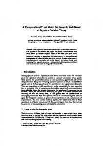
II. SYSTEM DESCRIPTION AND SETUP We consider a simplified view of the system as depicted in Fig. 1. The figure shows an electrolytic cell that is made up of a cylindrical crucible constructed out of Alumina. This crucible holds molten lithium carbonate (Li2CO3) electrolyte, which contains dissolved calcium carbonate (CaCO3) that needs to be electrolyzed. Electrolysis is performed by using two electrodes placed close to the center of the cylinder within the electrolyte. A steel cathode and an ickelanode are utilized. The crucible is heated uniformly from the outside using a suitable heat source, such as a heating element or solar energy. As long as the temperature is maintained higher than800◦C, the following reaction takes place:
Index Terms—Thermal modeling, electrolytic cell, heat transfer, electrical equivalence.
I. INTRODUCTION Electrolysis involves the use of electricity through molten or liquid solutions for driving chemical reactions, resulting in separation of materials. At the George Washington University, discovery of new molten salt chemistry has resulted in the use of electrolysis for calcium oxide (CaO) production from limestone (CaCO3), without the generation of carbon dioxide that is normally released in regular processes [1]. The underlying reaction requires a certain temperature threshold to be maintained, which motivates us to study the thermal energy movement in the system. The study of the energy balance in any electrolytic cell is essential in design and implementation [2]. We therefore begin with a simplified view of the system and derive the heat transfer model. To enable simulation of complex structures, as well as provide a framework for simulation on parallel computers, we study the use of electrical equivalent networks for the heat transfer. There are instances in the literature of similar efforts, for example, in the modeling of fuel cells through electrical equivalents [3]. In our specific case of the
CaCO3 → CaO + CO +
Manuscript received September 25, 2013; revised January 3, 2014. V. K. Narayana, O. Serres, and T. El-Ghazawi are with the Department of Electrical and Computer Engineering, The George Washington University, Washington, DC, 20052 USA (e-mail:
[email protected],
[email protected],
[email protected]). J. Lau and S. Licht are with the Department of Chemistry, The George Washington University, USA (e-mail:
[email protected],
[email protected]).
DOI: 10.7763/IJCTE.2014.V6.865
1 2
O2
(1)
Fig. 1. Basic electrolytic cell.
The generated calcium oxide precipitates out of the solution, and carbon monoxide can be collected for use in fuel generation. The electrochemical reaction is endothermic 215
International Journal of Computer Theory and Engineering, Vol. 6, No. 3, June 2014
and cools down the electrolyte. We model this cooling through an idealized reaction zone that absorbs heat, a cylindrical volume as shown in Fig. 1. This approximation is fine as long as we have long electrodes that span most of the crucible height, placed close to the center. Since this reaction zone absorbs heat, the temperature of the electrolyte will decrease, which may change the reactions taking place. We need to ensure that the coldest part of the solution will be above 800 °C, and thus seek to model the heat transfer in the system.
we have 𝑄 = 𝑘𝑤𝑎𝑙𝑙 𝐴
𝑑𝑇 𝑑𝑟
where 𝐴 = 2𝜋𝑟𝐿
(2)
Kwall is the thermal conductivity of the crucible wall, in W/m/K. In the steady state, the heat transfer rate Q˙ is a constant. Integrating (2), we get: Q 2πL
III. HEAT TRANSFER MODEL
𝑟2 𝑟1
𝑑𝑟 = 𝑘𝑤𝑎𝑙𝑙 𝑟
𝑇2
𝑑𝑇
𝑇1
Which gives
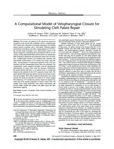
The external surface of the electrochemical cell is maintained at a constant temperature through a heating element. We therefore expect the temperature variation to be as shown in Fig. 2. Given the constant external temperature T2, the aim is to find the lowest temperature T0 in the steady state at the center of the electrolyte. This will give us an understanding of the required minimum value of T2.
𝑄=
𝑇2 −𝑇1
1 𝑟 ln 2 2π𝑘 𝑤𝑎𝑙𝑙 L 𝑟 1
(3)
where r2 is the radius of the outer wall, and r1 is the radius of the inner wall. Thus, for a known heat source that maintains a temperature T2 on the outer surface of the crucible, it is possible to have an estimate of the temperature T1 on the inner surface. B. Molten Salt
Fig. 2. Electrolytic cell temperature variation.
A. Crucible Wall
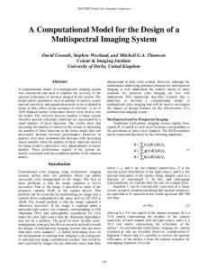
Fig. 4. Heat transfer in the molten salt region (reaction-free zone).
We now study the heat transfer through are gi on of the molten salt electrolyte that is not actively involved in there action process ata given moment, and thus does not contribute to any changes in the heat energy. The cylindrical portion used for analysis is depicted in Fig. 4. To simplify the analysis, we do not consider any heavy convection currents occurring in the molten solution. However, mild convection current scan be captured by an equivalent the rmal conductivity that includes convection and conduction. We denote this effective conductivity as ksalt. Following the steps similar to the crucible wall in Section III-A, we get Fig. 3. Heat transfer in the crucible wall region.
𝑄=
We first consider the heat variation in the crucible wall. As the heat transfer is radially in ward, we can model the heat conduction in one dimension and accurately obtain the temperature on the inner wall of the crucible. Fig. 3 shows a detailed diagram of the crucible section used in the model. The height of the cylindrical container is L. The figure shows an infinitesimal element of radius r and thickness dr. By conservation of energy, the quantity of heat entering this element should match the heat leaving this element, Q˙ (Joules/sor Watts). Using Fourier‟s Law for conduction [4], 216
𝑇1 −𝑇𝑐
1 𝑟 ln 1 2π𝑘 𝑠𝑎𝑙𝑡 L 𝑟 𝑐
(4)
where 𝑟𝑐 is the inner radius of the annular cylindrical region of the reaction-free molten salt. The reaction zone extends from the center till radius 𝑟𝑐 , and is analyzed next. C. Reaction Zone The reaction zone is the inner cylindrical region of the molten salt where the endothermic reaction occurs due to electrolysis of calcium carbonate. In this region, we consider the chemical reaction to consume heat at a rate „a‟ W/m3 or
International Journal of Computer Theory and Engineering, Vol. 6, No. 3, June 2014
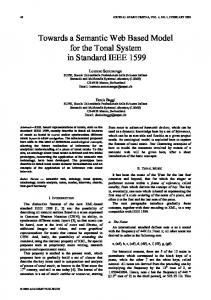
J/s/m3. Due to this heat absorption, the heat transfer rate 𝑄 does not remain the same as we go radially inward. We analyze this region using the diagrams in Fig. 5. The full zone is depicted on the left side in the figure.
We can then solve the differential equation in (9) to obtain a solution for the temperature function:
𝑇 𝑟 = 𝑇𝑐 +
𝑎
𝑟 2 − 𝑟𝑐 2
4𝑘 𝑧𝑜𝑛𝑒
(10)
The lowest temperature is expected at the center of the zone (r=0), which is:
𝑇0 = 𝑇𝑐 −
𝑎 4𝑘 𝑧𝑜𝑛𝑒
𝑟𝑐 2
(11)
Putting it all together, using (3), (4) and (11) we have: Fig. 5. Heat Transfer in the reaction zone.
𝑇0 = 𝑇2 −
Consider an infinitesimal annular cylindrical component of the reaction zone as indicated in the left side of Fig. 5, with a radial section as shown in detail on the right side in Fig. 5. The heat entering and exiting the region are respectively 𝑄 𝑟+∆𝑟 and𝑄 𝑟 . The amount of heat energy absorbed by the endothermic reaction in this zone is a ∆V, where ∆V is the volume of this infinitesimal region, given by, ∆𝑉 = 𝜋 𝑟 + ∆𝑟
2
− 𝑟 2 𝐿 ≃ 2𝜋𝐿𝑟∆𝑟
𝑄
1
2𝜋𝐿
𝑘 𝑤𝑎𝑙𝑙
ln
𝑟2 𝑟1
+
1 𝑘 𝑠𝑎𝑙𝑡
ln
𝑟1 𝑟𝑐
−
𝑎 4𝑘 𝑧𝑜𝑛𝑒
𝑟𝑐 2 (12)
The size of the reaction zone, 𝑟𝑐 , depends on the heat 𝑄 provided to the electrolytic cell. In the steady state, the heat transferred into the zone must be consumed fully by the endothermic reaction. In other words, 𝑄 = 𝑎𝑉 = 𝑎𝜋𝑟𝑐 2 𝐿
(5)
(13)
We can use this in (12) to give us a final expression for the value of 𝑇0 :
Through conservation of energy, we have,
𝑄 𝑟+∆𝑟 = 𝑄 𝑟 + 𝑎∆𝑉
(6)
Substituting for ∆V using (5), the relation in (6) becomes:
where 𝑟𝑐 =
𝑄 𝑟+∆𝑟 − 𝑄 𝑟 = 2𝜋𝐿𝑟𝑎 ∆𝑟 Which, as ∆𝑟 → 0, is the same as: 𝑑𝑄 𝑑𝑟
= 2𝜋𝐿𝑟𝑎
𝑇0 = 𝑇2 −
(7)
𝑑𝑇 𝑑𝑟
, 𝑤ℎ𝑒𝑟𝑒 𝐴 = 2𝜋𝑟𝐿
d𝑟 2
+
1 𝑑𝑇 𝑟 𝑑𝑟
=
𝑎 𝑘 𝑧𝑜𝑛𝑒
ln
𝑟2 𝑟1
+
1 𝑘 𝑠𝑎𝑙𝑡
ln
𝑟1 𝑟𝑐
+
1 2𝑘 𝑧𝑜𝑛𝑒
(14)
𝑄 /(𝑎𝜋𝐿) from (13). We can set the value of 𝑇0
V2=T2
I=Q’
V1=T1
Rwall
Fig. 6. Electrical equivalent for crucible wall.
(8)
V2=T2
where 𝑘𝑧𝑜𝑛𝑒 is the effective thermal conductivity of the reaction zone. Using the above expression for 𝑄 in (7), we obtain the following differential equation: 𝑑2T
1 𝑘 𝑤𝑎𝑙𝑙
to a required value (> 800 °C ). If we have a particular maximum temperature that we do not want to exceed on theouter surface of the electrolytic cell (say T2< 1100°C), we can determine the amount of heat that needs to be supplied to the cell. Conversely, if the amount of heat 𝑄 is known, the temperature distribution can be easily computed when we maintain 𝑇0 at the minimum required value.
We can determine 𝑄 (r) using Fourier‟s Law of conduction, which states that the time rate of heat flow is directly proportional to the temperature gradient across the infinitesimal element, as well as the area of cross section perpendicular to the flow: 𝑄 𝑟 = 𝑘𝑧𝑜𝑛𝑒 𝐴
𝑄 2𝜋𝐿
T1
I=Q’ Rwall
Vc=Tc Rsalt
Fig. 7. Electrical equivalent for two reaction-free regions.
IV. ELECTRICAL ANALOGY FOR HEAT TRANSFER (9)
It is well known that the heat transfer can be represented by an equivalent electrical analogue in most of the simple cases [5]. For our study, we seek to obtain an electrical equivalent in order to obtain computationally simpler alternatives, and to help with expansion to more complex experimental scenarios. We begin with the crucible wall. Due to conservation energy, the heat transfer rate is constant across the crucible wall in the radial direction. This may be likened to an
In order to solve this second order differential equation, we need boundary conditions. These are: 𝑇|𝑟=𝑟𝑐 = 𝑇𝑐 𝑑𝑇 =0 𝑑𝑟 𝑟=0 217
International Journal of Computer Theory and Engineering, Vol. 6, No. 3, June 2014
respectively. Also, using 𝑟𝐽 − 𝑟(𝐽 −1) = ∆𝑟 , followed by Taylor series expansion/approximation, we get:
electrical current, and therefore we can model the crucible using a lumped resistor equivalent. Looking at Fig. 6 and (3), we can deduce that the equivalent resistance is:
𝑅𝑤𝑎𝑙𝑙 =
1 2𝜋𝑘 𝑤𝑎𝑙𝑙 𝐿
ln
𝑟2
𝑇𝑐 − 𝑇0 =
(15)
𝑟1
1 2𝜋𝑘 𝑠𝑎𝑙𝑡 𝐿
ln
𝑟1
(16)
𝑟𝑐
where 𝑟𝑐 is obtained from (13) as noted earlier. Thus the first two regions can be represented as shown in Fig. 7, and the heat transfer can be easily computed as: 𝑄=
𝑇2 − 𝑇𝑐 𝑅𝑤𝑎𝑙𝑙 + 𝑅𝑠𝑎𝑙𝑡
Let us now consider the reaction zone. Due to the existence of the endothermic reaction, the heat transfer rate does not remain the same as we traverse radially in ward. Since 𝑄 , the equivalent of current, is not constant, we cannot model the region as a lumped resistor. Instead, we split the zone radially into many small elements, so that each element can be captured as a resistance. The heat absorption within each element can then be modeled as a current source. The resulting network is shown in Fig. 8. The current (heat absorbed) at each element J is given by a∆𝑣 , where the volume ∆𝑣 of the annular cylindrical element is given by π𝐿(𝑟𝐽 2 − 𝑟(𝐽 −1) 2 ). Therefore, 𝐼𝐽 = 𝑎𝜋𝐿 𝑟𝐽 2 − 𝑟(𝐽 −1) 2
V. CONCLUSION In this paper, we took the example of an in-house electrolysis system, outline das implified version fit, and provided the first steps in developing a heat transfer model. We derived the thermal model and the electrical equivalents. Through the specific example chosen, we showed that simple, lumped electrical equivalents are not directly applicable. By obtaining the electrical networks for heat transfer, we made observations on its applicability for a wider ange of structures, as well as amenability for parallel computing. Future work would involve a study for incorporating non-ideal factors into this simple model, as well as carrying out a parallel implementation.
(17)
Furthermore, the resistance of this element can be easily derived based on our analysis of the crucible wall:
𝑅𝐽 =
TC
1 2𝜋𝑘 𝑧𝑜𝑛𝑒 𝐿
RN
ln
𝑟𝐽
RJ
R2
IJ
IN
I2
ACKNOWLEDGMENT This work was supported in part by the National Science Foundation under grant number CHE-1230732.
(18)
𝑟 (𝐽 −1)
REFERENCES
R1
T0
[1]
I1 [2]
Fig. 8. Electrical equivalent for the reaction zone.
[3]
From the circuit in Fig. 8, we can now apply Kirchoff‟s law and Ohm‟s law to easily obtain the temperature difference between the outer and inner point of the reaction zone:
[4] [5]
𝑁
Vikram K. Narayana received the B.E. degree in electronics and communication engineering from Mysore University, India in 2000, and the Ph.D. degree from the Indian Institute of Technology Madras, India, in July 2006. He is currently an assistant research professor in the Department of Electrical and Computer Engineering at The George Washington University. In the past, he has worked for Wipro Technologies, Siemens Corporate Technology, and
𝑖=1 𝐽
𝐽 =1
𝑖=1
=
S. Licht, H. Wu, C. Hettige, B. Wang, J. Asercion, J. Lau, and J. Stuart, “Step cement: Solar thermal electro chemical production of cao without co2 emission,” Chemical Communications, vol. 48, no. 48, pp. 6019–6021, 2012. M. Taylor, W. Zhang, V. Wills, and S. Schmid, “Adynamic model for the energy balance of an electrolysis cell,” Chemical Engineering Research and Design, vol. 74, no. 8, pp. 913–933, 1996. A. Salah, J. Gaber, R. Outbib, O. Serres, and H. E. Sayed, “Modeling and simulation of pemfuel cell thermal behavior on parallel computers,” Energy Conversion, IEEE Transactions, vol. 25, no. 3, pp. 768–777, 2010. Y. A. C ¸engel and A. J. Ghajar, Heat and Mass Transfer: Fundamentals and Applications, ch. 3: Steady Heat Conduction, McGraw-Hill, 2011. T. L. Bergman, A. S. Lavine, F. P. Incropera, and D. P. DeWitt, Introduction to Heat Transfer, 6th ed. John Wiley and Sons, 2011.
𝐼𝑖 𝑅𝑁
𝑇𝑐 − 𝑇0 = 𝐼1 𝑅1 + 𝐼1 + 𝐼2 𝑅2 + ⋯ + 𝑁
(19)
In the limit N→∞, this expression matches exactly theone in (11) obtained by solving the second order differential equation in Section III-C. Based on this functional equivalence of the model, we can extend the electrical equivalent network for more complex structures. Irregularities or non-uniformities in the structure of the electrolysis cell will render hand derivation of the differential equations rather impractical. By using the electrical equivalent described in this section, it would be possible to capture any structure by decomposing it into a number of small elements. Furthermore, it is possible to distribute the computations associated with this large number of elements across a parallel computing cluster, thereby providing the potential for speeding up the simulations.
Similarly, the equivalent resistance of the molten salt reaction-free zone is:
𝑅𝑠𝑎𝑙𝑡 =
𝑎 𝑁(𝑁−1) 𝑟2 4𝑘 𝑐 𝑁2
𝐼𝑖 𝑅𝐽
We can now substitute for 𝐼𝑖 and 𝑅𝐽 based on (17) and (18) 218
International Journal of Computer Theory and Engineering, Vol. 6, No. 3, June 2014 STMicroElectronics in Bangalore, India. His research interests include reconfigurable computing, high-performance and GPU computing, embedded systems and systems-on-chip. He is a Senior Member of the IEEE and IEEE Computer Society.
Society Energy Technology Research Award, GWUs Trachtenberg Faculty Scholarship Award, the Gustella Award of the Technion, and held the Carlson Endowed Chair in Chemistry at Clark University. Stuart Licht‟s research is conducted in state-of-the-art facilities at the GWU Science and Technology Campus with specialized solar chemical, electrochemical and environmentalcapabilities, and with research support from the National Science Foundation, DOE, ONR, USAF, and industry.
Olivier Serres is currently a Ph.D. student in the Department of Electrical and Computer Engineering at The George Washington University. He is also a senior research assistant at the High Performance Computing Laboratory. He obtained a research Masters degree in mechatronics and a computer science engineering degree from the University of Technology of Belfort-Montbeliard, France. His research interests include high-performance computing and reconfigurable computing. For his Ph.D. dissertation, he is currently researching programming models for high-performance many-core based and heterogeneous systems.
Tarek El-Ghazawi is a professor in the Department of Electrical and Computer Engineering at The George Washington University, where he leads the university-wide Strategic Program in High- Performance Computing. He is the founding director of The GW Institute for Massively Parallel Applications and Computing Technologies (IMPACT) and a founding co-director of the NSF Indus- try/University Center for High-Performance Reconfigurable Computing (CHREC). His research interests include high-performance computing, parallel computer architectures, high-performance I/O, reconfigurable computing, experimental performance evaluations, computer vision, and remote sensing. He has published over 200 refereed research papers and book chapters in these areas and his research has been supported by DoD/DARPA, NASA, NSF, and also industry, including IBM and SGI. He is the first author of the book UPC: Distributed Shared Memory Programming, which has the first formal specification of the UPC language used in high-performance computing. Dr. El-Ghazawi is a member of the ACM and the Phi Kappa Phi National Honor Society. He is a fellow of the IEEE.
Jason Lau received his bachelor degree in chemical education from the University of California, San Diego in 2008. He is currently a graduate student with the Department of Chemistry at The George Washington University, performing research under the guidance of Professor Stuart Licht. He previously worked as a chemist for CaptekSoftgel International in Cerritos, California. His research interests are in renewable energy utilization with an emphasis in carbon dioxide emission reduction and solar energy utilization. Stuart Lichtis a professor in the Department of Chemistry at the George Washington University (GWU) with active research in sustainability, and over 300 peer-reviewed publications and patents. He completed his Ph.D. at the Weizmann Institute, and a postdoc at MIT. Prior to arriving at GWU in2008, he served as a program director at the NSF and was the chair of Chemistry at UMass, and has received awards including the Electrochemical
219