... Gabriele Taentzer, Stefan Jurack, Tim Schäfer. Philipps-Universität Marburg, Germany,. {strueber,taentzer,sjurack,timschaefer}@mathematik.uni-marburg.de.
Towards a Distributed Modeling Process Based on Composite Models Daniel Strüber, Gabriele Taentzer, Stefan Jurack, Tim Schäfer Philipps-Universität Marburg, Germany, {strueber,taentzer,sjurack,timschaefer}@mathematik.uni-marburg.de
Abstract. The rising impact of software development in globally distributed teams strengthens the need for strategies that establish a clear separation of concerns in software models. Dealing with large, weakly modularized models and conflicting changes on interrelated models are typical obstacles to be witnessed. This paper proposes a structured process for distributed modeling based on the modularization technique provided by composite models with explicit interfaces. It provides a splitting activity for decomposing large models, discusses asynchronous and synchronous editing steps in relation to consistency management and provides a merge activity allowing the reuse of code generators. All main concepts of composite modeling are precisely defined based on category theory.
Keywords: distributed modeling, composite models, model transformation, EMF
1
Introduction
Nowadays, model-driven development is a widely-spread paradigm to cope with the growing complexity of software requirements. Reliable technologies have emerged that allow specifying an application on a high level of abstraction using models. These models can then be transformed towards a running software system. Model-driven development is based on modeling languages that are usually defined using meta-modeling: a meta-model defines a language of individual models by predefining their structure. An important meta-modeling architecture has been proposed by the Object Management Group in terms of the Meta Object Facility (MOF) [14]. An essential subset of MOF has been implemented by the Eclipse Modeling Framework (EMF) [5]. When lifting concepts and tools from model-driven development to a distributed environment, a couple of challenges arise: contributors at different locations might be responsible for models that are interconnected in some sense. Thus, clear conditions and conventions for the editing of models are required to avoid the emergence of inconsistencies. Another drawback of existing tools is the sometimes monolithic nature of large models. Large models are difficult to comprehend and maintain. Thus, welldefined modularization strategies for models are required. EMF models can be modularized using remote references between individual models. The targets of remote references are then temporarily represented by proxy elements and on demand replaced by the actual model element. In consequence, logically, all involved models constitute one big model. While this technique is sufficient for distributing a large model over a set of resources, it does not establish well-known engineering
principles such as encapsulation and information hiding. Hence, we refer to this approach as a physical modularization technique. In opposition, we propose composite models [8] as a logical modularization technique that establishes information hiding and allows for local consistency checks. A composite model comprises a set of components that are interconnected by export and import interfaces. Possible topologies of model components are predefined by meta-model components. We provide core tool support for composite models and their transformation. This paper utilizes composite models in order to address three questions that arise when lifting model-driven development to a distributed environment: (1) How can a model be decomposed for logical modularization? (2) How can models be edited in a distributed way such that consistency between model components is preserved? (3) How can model-to-code transformation be performed when models are distributed? Our solution to these questions is a process for distributed modeling. In order to tackle question (1), a split activity is elaborated that decomposes a given model into a set of components forming a composite model. As for question (2), we discuss how editing steps can be specified and performed in a systematic way using composite model transformation. As a tentative solution to question (3), a merge activity is introduced that allows the reuse of existing code generation components. The remainder of this paper is structured as follows: Sect. 2 provides the modeldriven development of web applications as a running example. Composite models are recapitulated in Sect. 3. An overview of the process forming the main contribution of this paper is given in Sect. 4. The activities constituting the process – split, edit, and merge – are elaborated in Sects. 5, 6, and 7. We present an application scenario in Sect. 8 and tool support in Sect. 9. Related work is discussed in Sect. 10. Sect. 11 concludes.
2
Scenario: Model-driven development of web applications
Web applications as a software domain have undergone domain analysis in visual web modeling languages such as WebML [3] or UWE [11]. A common design decision found in these modeling languages is their branching into a set of viewpoint-oriented sub-languages – such as a structural data model, a presentation model and a navigation model. When a web application is to be developed by a distributed team, it is likely that the contributors obtain responsibilities for the different viewpoints, e.g. one contributor acts as domain modeler and another one as presentation modeler. Hence, we consider this scenario as suitable for distributed modeling. To provide a full model-driven development infrastructure, domain-specific languages such as WebML and UWE are supplemented with code generation facilities that define a language semantics. As a running example, Fig. 1 provides the syntax for the Simple Web Application Language (SWAL) as a modeling language for the specification of simple web applications1 . SWAL is specified by means of an EMF meta-model, comprising attributed model classes as nodes with directed references as edges. Classes may be abstract. References may be containment references that ensure a tree-like structure for models. 1
The development of SWAL was initiated by Manuel Wimmer and Philip Langer at the Technische Universität Wien and reimplemented for its use in modeling courses at the PhilippsUniversität Marburg.
2
DataModel dataTypes DataType
Attribute
HypertextModel
entities Entity entity
features Feature
type
dataModel
Link
startPage links target
type
Reference
pages Page
DynamicPage
IndexPage
StaticPage
DetailsPage
Fig. 1: SWAL meta-model.
The class HypertextModel is used as root object of a web application to be specified. It contains a hypertext structure of interconnected pages and a DataModel for the specification of structural models of persistent data. Persistent data is based on distinct Entities which are charaterized by a number of Features, i.e. Attributes and References. An attribute is typed over a primitive DataType, a reference over an entity. The hypertext structure is based on Pages being interconnected through Links. Depending on its content, a page can either be dynamic or static. A dynamic page refers to an entity and can either be an index page displaying a list of available data records or a details page presenting a detailed view for a specific record. Based on these concepts, in Fig. 2 a poetry competition web application is specified. Contest, poet, and poem entities are to be displayed on interlinked index and details pages. The concrete syn- Fig. 2: Poetry contest web application tax given in the presentation facilitates model. convenient editing by hiding the DataModel and HypertextModel classes: pages and entities are visualized as nodes in different layouts. Hyperlinks, entity links, and references are visualized as arrows.
3
Composite Models
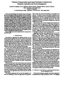
This paper investigates a process for distributed modeling based on composite models. Composite models provide a logical modularization technique for models by declaring explicit export and import interfaces. Export and import interfaces identify model elements provided to and obtained from the environment, respectively. While an import is assigned to exactly one export, an export can serve an arbitrary number of imports. The core of a component is a conventional model called the body. Interfaces are characterized as sub-models of this body. While the model elements in export and import 3
B E
B E
I
E
Network Level
Object Level
Fig. 3: Composite model with explicit export and import interfaces (taken from [7])
interfaces are identified with body elements, import interface elements are also identified with export elements to establish interconnection. An interface can hide structural complexity of its component body, e.g. by flattening its inheritance hierarchy. The interface structure of model components is predefined by meta-model components. Consider Fig. 3 for a schematic representation of an example composite model with explicit export and interfaces. The network level constitutes a topology of components comprising body, export, and import nodes and interconnecting edges. The object level comprises a set of interrelated models, each providing a refinement for one of the network nodes, with interrelating mappings. Dashed arrows indicate how interfaces are identified with body models, dotted arrows indicate an assignment between an import and an export interface. Mappings on object level are compatible with network level arrows in the sense that source and target nodes of mapped arrows are mapped to source and target of the image arrow. Formalization. The internal representation of models can be well represented by graphs. Therefore, the basis of our formalization are typed graphs and graph morphisms as defined in e.g., [4,9]. They form the category G RAPHST G . Since the following definitions of composite graphs and graph morphisms are given in a category-theoretical way, it is also possible to use other kinds of graphs and morphisms as basic ingredients of composite graphs. For example, composite graphs over typed graphs with inheritance and containment are considered in [9]. Definition 1 (Composite network graph). A composite network graph is a graph G typed over graph CN G (shown on the right) by a graph morphism t : G → CN G such that the following constraints hold: (1) each export node is source of exactly one network edge running to a body node and (2) each import node is source of exactly two network edges, one edge is running to a body node and the other to an export node. If there are export nodes without outgoing edges, corresponding composite network graphs are called weak. 4
Definition 2 (Composite network graph morphism). Given two network graphs g : G → CN G and h : H → CN G, an injective graph morphism f : G → H forms a valid composite network graph morphism, short network morphism, if h ◦ f = g. Composite network graphs and network graph morphisms form a category, called C OMPO N ET G RAPHS, that is co-complete [9]. Weak composite network graphs and their morphisms also form a category, however, this one does not have pushouts. Definition 3 (Composite Graph). Given a (weak) composite network graph G, a (weak) ˆ over G is defined as G ˆ = (G, G(G), M(G)) with composite graph G – G(G) being a set of graphs, called local graphs, of category G RAPHS with each ˆ ˆ graph uniquely refining a network node in GN : G(G) = {G(n)| G(n) is a graph and n ∈ GN }, ˆ ˆ ˆ ˆ ˆ ˆ ˆ ˆ – for all paths G(x) ◦ G(y), G(z) : G(A) → G(B) we have G(x) ◦ G(y) = G(z). (commutative morphisms) ˆ Definition 4 (Composite Graph Morphism). Given two (weak) composite graphs G ˆ and H with composite network graphs G and H, resp., a (weak) composite (graph) ˆ → H, ˆ is a pair fˆ = (f, m) where morphism, written fˆ: G – f : G → H is a composite network graph morphism and – m is a family of morphisms fˆ(i) ˆ ˆ N (i)) / H(f G(i) i {fˆ(n) | n ∈ GN } such that • for all nodes i ∈ GN : ˆ ˆ E (e)) e ˆ ˆ N (i)) is a G(e) H(f fˆ(i) : G(i) → H(f � � graph morphism and � fˆ(j) ˆ ˆ N (j)) / H(f j G(j) • for all edges e : i → j ∈ GE : ˆ ˆ ˆ ˆ H(fE (e))◦ f (i) = f (j)◦ G(e) (see the illustration on the right). If morphism f and all morphisms in m are inclusions (injective), fˆ is called inclusion ˆ → TˆG is called typed (injective). Given a graph TˆG and a composite morphism tˆ : G composite graph. Composite graphs and graph morphisms form a category, called C OMP G RAPHS, being co-complete. Weak composite graphs and weak composite morphisms form category C OMP G RAPHSweak . C OMP G RAPHST G is the category of typed composite graphs and their morphisms. (See [9].) This formalization induces that composite graphs are consistent in a certain sense: Since all morphisms have to be total, especially the ones between import and export interfaces, inconsistencies between components in the sense of unsatisfied imports may not occur. It is up to future work to adapt composite models such that temporary inconsistencies are tolerated, i.e., partial import mappings are allowed.
4
Distributed modeling process: overview
In this section, we give an overview on a modeling process that addresses three issues to facilitate distributed model-driven development: (i) How can composite models be 5
used to structure models that lack an appropriate modularization? (ii) How can composite models be edited systematically so that inconsistencies are avoided? (iii) How can composite models be used as a blueprint for code generation? We refer to this process as a distributed process in terms of a collection of activities that enable a distributed team to work on a logically modularized model.
Fig. 4: Distributed modeling process.
Fig. 4 gives an outline of the process: When applying composite models to an existing software development project, a monolithic model may exist that is required to be decomposed. In order to support this, we propose a splitting technique. In the distributed modeling phase following up, editing steps are performed, involving asynchronous or synchronous editing as well as changes of the network structure. Afterwards, in order to support code generation, all components may be merged together. The resulting code may have gaps to be filled in by the distributed team. Please note that this overview refers to models on an arbitrary meta-level, e.g. models in application development or language development. However, the full potential of the process becomes evident when it is applied on two interrelated levels, e.g., application and language development. For instance, a legacy meta-model may be split by language developers. Conforming application models are then split according to the language decomposition by application developers. This notion is elaborated further in the following sections presenting the outlined modeling activities.
5
Model splitting
This section elaborates on model splitting as a migration technique for introducing the logical modularization technique provided by composite models to existing software development projects. It assumes a monolithic model or a set of models interconnected by remote references and produces a composite model comprising a set of model components interconnected by export and import interfaces. Meta-models as well as their 6
dataTypes DataType type
features
entities Exp Entity type
Feature
Attribute
dataModel
Imp
DataModel Entity
DataModel
entities Link
links
Page
target
entity
DynamicPage Reference
IndexPage
SwalData
HypertextModel pages startPage StaticPage
DetailsPage
SwalHypertext
Fig. 5: Result of splitting SWAL into meta-model components
Fig. 6: Result of splitting the poetry model along the SWAL component split
conforming models can be split. As we will prove for the special case of binary splitting, i.e., the decomposition into two components, the split of a typed model can even be uniquely derived from the split of its meta-model. Example 1. In Fig. 5, SWAL has been split in two meta-model components comprising classes related in their belonging to a specific viewpoint: domain modeling and hypertext modeling. Both resulting components are self-contained units in the sense that all model references run between classes within the same component. However, they are also interrelated as they are equipped with interfaces. SwalHypertext’s import interface contains DataModel and Entity classes mapped to the DataModel and Entity classes provided by SwalData’s export which allows for the exchange of data models. Finding a proper decomposition for meta-models is challenging since it can largely benefit from automation, but on the other hand, may require some human intervention. A heuristics may be used to recommend a reasonable decomposition to the stakeholder based on some indicators of interrelation: e.g., as it is the case in the example, a high coupling of references, especially of containments, indicates classes often instantiated in combination. In turn, a stakeholder might consider it desirable to reveal more classes in interfaces than a minimal subset, e.g. he might want to provide the references running between entities to support comprehension. In any case, the benefit from finding an appropriate decomposition becomes evident considering the split of conforming models. 7
In Fig. 6, the poetry contest model is split towards the viewpoint meta-models introduced in Fig. 5. For better readability, exported model elements are shown separated from their body elements. Both meta-model components are instantiated by conforming model components. Especially, export and import interfaces are instantiated and used for the sharing of entities between both components. As the split follows the typing of model elements and their assignment to meta-model components, it can be automatized. Formalization. In the following, a formalization is provided for splitting a meta-model in two meta-model components with intermediate export and import interfaces and, furthermore, for splitting conforming models along that split. Any meta-model that can be represented as a plain graph can be used as input, e.g., a single self-contained model or a group of models interconnected by remote references. Proposition 1 (Binary split of a composite graph). Given graph G and two subgraphs G1 and G2 with inclusions g1 : G1 → G and g2 : G2 → G, their interconnecting interfaces can be uniquely determined such that the resulting diagram forms a valid composite graph with two components. Proof. Let square (1) in the figure below be a pullback and (2) an epi-mono-factorization. Then, graph GI and morphisms i1 and i2 are uniquely determined, up to isomorphism. The epi-mono-factorization splits morphism i2 into a surjective and an injective part. Graph GE and morphisms e2 and ie are uniquely determined by this factorization. Diagram i1 , ie, and e2 forms a valid composite graph with two components. Its network graph is well typed over the component network graph defined in Def. 1. Proposition 2 (Binary split of a typed composite graph). Given a type graph T G with its subgraphs T G1 and T G2 and a binary split as in the upper part of the figure below. Moreover, graph G with its typing t over T G is given. There is a unique binary split of G being type compatible with the resulting composite type graph. I.e. all morphisms in the diagram below exist and form a commuting diagram. The result is a composite graph typed over the split of TG. Proof. The following steps can be performed: 1. (t1 , g1 ) is constructed as pullback over (t, tg1 ). 2. (t2 , g2 ) is constructed as pullback over (t, tg2 ). 3. (ti , i1 ) is constructed as pullback over (ti1 , t1 ). 4. Morphism i2 is the induced morphism by pullback (t2 , g2 ) and morphisms g1 ◦ i1 and ti2 ◦ti such that t2 ◦i2 = ti2 ◦ti and g1◦i1 = g2 ◦ i2 . 5. (e2 , te ) is constructed as pullback over (t2 , te2 ). 6. Morphism ie is the induced morphism by the pullback (e2 , te ) and morphisms i2 and ti ◦ tie such that i2 = e2 ◦ ie and tie ◦ ti = te ◦ ie. 8
o TG O 1
ti1
TG O I
tg1
� o TG O
ti2
� o TG O 2
t1 tg2
t i1 2
G1 o
t g1
� Go
(1) g2
i2
� G2 o
tie te2 ti
� T GO E
GI
te
(2)
ie
e2
� GE
Considering the view-oriented splitting of large meta-models as e.g. for UML, it makes sense to iterate several binary splits. An example split scenario for UML can look like this: (1) split the structure component from the behavioral component, (2) split the structure component further into package and class structure components, (3) split the behavioral component into a basic action component and a behavior diagrams component, and (4) continue splitting this component until the well-known behavior diagrams are each separated in model components. Of course, component interfaces have to be continuously adapted during this splitting process.
6
Distributed model editing
A crucial challenge of collaborative editing is to preserve the consistency of models while keeping editing steps as independent as possible. Several approaches to the handling of model inconsistency, being defined as the maintenance of contradictory information within a network of models, center on the detection and resolution of inconsistencies [13] [6]. These approaches rely on facilities to perform a global consistency check on the distributed model which, though, might not always be available, e.g., for security reasons or due to network failures. Hence, we propose a complementary strategy of inconsistency avoidance, giving editing steps at hand that are classified as either safe or critical to the consistency of models. We provide the notion of a relaxed consistency avoidance that allows performing critical steps if necessary. In contrast, a strict inconsistency avoidance may be an obstacle to the natural evolution of a software project and is prone to dead-lock situations. Existing collaborative model editors such as Papyrus [15] or MagicDraw [12] implement a strategy for inconsistency avoidance by locking selected model parts for modification. These editors follow an asynchronous approach to editing single models that can be displayed and modified in multiple distributed editors at once. As for the use of composite models, the management of consistency is facilitated by the maintenance of interfaces. It is desirable to support asynchronous and synchronous editing steps: for instance, two related components with related contents might be expanded by individual contributors or in parallel by one contributor. Thus, this section discusses asynchronous as well as synchronous editing steps and their formalization based on the transformation of composite graphs. Using our basic implementation of composite model transformation comprising a rule editor and interpreter engine tool suite, it is possible to deploy transformation rules as editing steps, e.g. refactorings, within an existing editor such as Papyrus. Example 2. For the poetry contest application specified in the Fig. 6, new requirements might be stated, e.g., the management of books. When domain and hypertext components are developed independently, the first action done is that the domain modeler adds this new entity to the body and export of the swaldata component. The hypertext modeler then adds the entity to the import interface and body of the swalht component and creates corresponding pages for the entity resulting in the model shown in Fig. 7. In contrast, it might also be desirable to perform these changes in parallel: e.g., imagine an editing command that adds an entity and corresponding pages to both components. We distinguish these two kinds of editing as asynchronous and synchronous editing. 9
Fig. 7: Model components after editing. Thick borders indicate newly added elements.
Formalization. Synchronous and asynchronous editing steps can be formalized as model transformations on a composite model. Definition 5 (Composite graph transformation). ˆ
l rˆ ˆ ←ˆ ,→ ˆ type) ˆ conGiven a composite graph TˆG, a composite graph rule pˆ = (L K R, ˆ→ ˆ ˆ ˆ ˆ ˆ = (type ˆ ˆ: L sists of composite graphs L, K, and R typed over T G by the triple type L ˆ → TˆG, type ˆ → TˆG) being composite morphisms and typed ˆ ˆ: K ˆ ˆ: R TˆG, type K R ˆ ˆ ˆ ˆ ,→ R ˆ being inclusions such that ∀n ∈ composite morphisms l : K ,→ L and rˆ : K ˆ
l(n) rˆ(n) ˆ ˆ ˆ ˆ KN : pˆ(n) = (L(n) ←- K(n) ,→ R(n), type(n)) is a graph rule (as defined in e.g. [4]). p, ˆm ˆ ˆ =⇒ ˆ A composite IC-graph transformation (step) G H ˆ l ˆo ˆ � rˆ / R ˆ ? _K L ˆ to H ˆ by a (weak) comof a typed composite graph G posite graph rule pˆ and a typed injective composite morˆ n ˆ (1) dˆ (2) ˆ → G ˆ is given on the right, where (1) and m phism m ˆ:L � � � ˆ (2) are pushouts in the sub-category of C OMP G RAPHST G h ˆ o gˆ ? _ D ˆ� ˆ /H G (C OMP G RAPHSweak ) with injective morphisms only. TG ˆ0 ⇒ G ˆ 1 ⇒ ... ⇒ G ˆ n of direct A composite graph transformation is a sequence G ∗ ˆ ˆ composite graph transformations, written G0 ⇒ Gn .
A composite transformation can be performed component-wise, i.e., performing the network transformation first and all local transformations for preserved network nodes p, ˆm ˆ ˆ =⇒ ˆ can be performed if m afterwards. Transformation step G H ˆ fulfills the composite gluing condition ensuring that the resulting structure is again a well-formed composite graph. Otherwise, it can happen that context edges dangle afterwards. The gluing condition has to be checked on the network and all local transformations. Moreover, for all network nodes that shall be deleted their local graphs have to be fully determined by the match and local graph elements may be deleted only if there are no preserved interface elements being mapped to them. Weak composite rules are not allowed to change stand-alone exports and to produce stand-alone exports by deleting their body graphs. (For more details see [7].) 10
Fig. 8: Synchronous and asynchronous composite model transformation rules. Example 3. Two sample composite rules, shown in a compact representation, are proˆ −K ˆ vided in Fig. 8. «Del» and «New» keywords denote nodes as being contained in L ˆ ˆ or R − K, respectively. Rule a) is a synchronous rule specifying the addition of a new entity and corresponding index and details pages to both components in parallel. Rule b) is an asynchronous rule removing an entity from a body and an adjacent export. Applying rule a) to the composite model in Fig. 6 yields a composite graph. Since nothing is deleted, the composite gluing condition is obviously fulfilled. To obtain the composite model in Fig. 7, additional references between book, poem, and poet have to be added by another editing step. Wrt. global consistency, rule a) is evidently neutral as an intact export/import relation is introduced. The editing step specified by rule b) is to be considered a critical one since the export interface being edited might be referred to from a remote import interface. Hence, a user performing an editing step like this may be warned and suggested to clarify the editing step to his collaborators.
7
Model merging for code generation
Aiming at providing a full life-cycle of modeldriven development, code generation as a semantics for composite models is to be investigated. Generally speaking, two different strategies are conceivable: A distributed code generation allowing the successive code generation for individual components is an interesting idea deserving further research. However, in this section, we focus on the second strategy: Existing code generators can be reused to perform a centralized code generation. As input for the generator, a single model conforming to the original language before the Fig. 9: Merged application model. language split is required. We provide a technique to support the merging of a composite model to a single model serving as a blueprint for code generation. 11
Example 4. Fig. 9 shows how the composite model provided in Fig. 7 is merged. The merge exploits the information available in import and export interfaces: Pairs of objects are identified as corresponding and can thus be merged. The result of the merge is welltyped because it conforms to the original pre-split meta-model. A merge of meta-models can be performed applying the same strategy. Formalization. We provide a formalization for the merge of a composite model. Proposition 3 (Graph merge). Given a composite graph, there is a unique graph containing its merge result. Proof. Considering a composite graph C as a diagram in category G RAPHST G , its colimit consists of a simple graph G and a family of graph mophisms from all local graphs of C to G. The colimes construction is uniquely determined.
8
Application scenario
This section provides a simple application scenario to show how the distributed process is applied. The scenario, illustrated in Fig. 10, concerns with web application development based on the SWAL web modeling language. We assume that the language already has been subject to a split into domain and hypertext components that was performed by the language developers.
Fig. 10: Scenario for distributed editing process
The starting point is a monolithic model M conforming to SWAL. M is logically distributed when project manager Samantha performs a split along the given languagelevel decomposition. The resulting composite model comprises domain model component D and hypertext model component H being interconnected by means of export and import interfaces. Samantha now assigns team members to viewpoints: Frank receives 12
responsibility for domain modeling, Mike becomes the hypertext modeler. The internal details of remote components are hidden to both developers respectively: Frank’s scope of visibility is restricted to his assigned component, D. Mike’s scope of visibility comprises his assigned component, H, and remote component D’s export (cf. the concept of weak composite graphs introduced in Sect. 3). From now on, Frank and Mike perform asynchronous editing steps, reflected in increasing version numbers. The first steps performed are neutral to inter-model consistency and do not require conflict handling. Eventually, the transformation from D2 to D3 is a critical editing step threatening global consistency, e.g. the deletion of a model element being visible in the export. Hence, when performing this editing step, Frank receives a warning. His options are: to manually establish communication to Mike clarifying the change, to let a default message be delivered to Mike, to take back the change or to do nothing. In the two former cases, Mike can react by performing an editing step such that consistency is retained. When doing nothing, consistence might be broken. Later on, Samantha performs a synchronous editing step changing both components in parallel. Eventually, she decides that the model components have accomplished a solid state and should be merged for code generation. A global consistency check may be performed before the merge to ensure a valid result. If at some later point in time new requirements are added, further editing can be performed on the components in their state before the merge. To summarize, the maintenance of explicit export and import interfaces allows to reason about a smart and relaxed conflict avoidance: at all times, developers are aware whether their editing is either safe or critical to inter-model consistency. In the case of critical steps, further intervention may become necessary. However, an automatized conflict detection and resolution algorithm can be considered complementary and might be applied at any time throughout the development process. Especially a conflict detection step right before the code generation step is highly desirable.
9
Tool support
The core processing of composite models is supported by an existing editor environment based on the Eclipse Modeling Framework. For a set of individual models, wizard tools are provided allowing the derivation of export and import interfaces in order to establish model interconnection. Export and import interfaces are implemented as separate resources with special references, supported by a delegation mechanism that replaces EMF’s proxy concept. Furthermore, we have implemented a model transformation language and tool set allowing the specification and execution of editing steps that can be integrated in an existing editor. The tool set is open source being provided at http://www.uni-marburg.de/fb12/swt/forschung/software along with examples and a tutorial. The automation of splitting and merging is left to future work.
10
Related Work
In this section, we compare our work to several other approaches for dealing with large and distributed models. 13
10.1
Model slicing
The extraction of sub-models from large models has been considered under the heading of model slicing. [2] presents a tool that allows defining model slicers for domainspecific languages by determining a selection of classes and features to extract. [10] provides an elegant formalization of model slicing as they prove that the sub-models gained from slicing along particular references constitute a lattice. A linear-time algorithm establishing this decomposition is elaborated. These approaches differ from model splitting in so far as they aim at extracting sub-models conforming to the same meta-model as the model to be sliced. In turn, model splitting is integrated into an overlying process: a meta-model is split in several components. Afterwards, models based on these meta-models are split towards these components. The splitting of a model towards components with export and import interfaces is specific to our approach. 10.2
Consistency management in distributed modeling
As discussed before, we propose a relaxed inconsistency avoidance as a supplementary strategy to inconsistency detection and resolution. An elaborated strategy for the latter is given by Macromodeling [16]. Macromodeling allows integrating multiple models of different modeling languages on type and instance layers. A major objective of macromodeling is the check of global consistency conditions based on logical formulas. However, it does neither envision a specific modeling process nor the use of explicit interfaces. 10.3
Model weaving
The merge of models can be compared to the weaving of models that is implemented by different tools, e.g., Atlas Model Weaver (AMW) [1]. AMW allows the weaving a set of models by constructing a weave model based on a weave meta-model. It supports the manual and semi-automatic weaving of models by means of heuristic-based transformations. Our merging, in turn, is restricted to composite models as input models. It can be fully automatized exploiting the information given by import/export relations.
11
Conclusion and Outlook
The global distribution of software development spawns a need for new well-defined software engineering methods. The process presented in this paper is our contribution to satisfying this need. It proposes split, edit and merge activities based on composite models which have been introduced as a formally sound modularization mechanism, allowing for local consistency checks and systematic transformation. Future work is the enhancement of existing tool support towards a comprehensive tool environment supporting all parts of the presented distributed modeling process. Firstly, we aim at providing convenient editor support that allows editing components equipped with interfaces at the right level at abstraction. Secondly, splitting and merging are to be automatized. It is of our particular interest to find a heuristics that gives reasonable suggestions for splitting. Thirdly, in addition to the centralized code generation 14
approach introduced here, a distributed code generation facility shall be implemented. In particular, it is to investigate how import/export relations are dealt with when generating code for individual components. Having a suitable tool support at hand, we are heading towards larger examples that show the scalability of this approach. We are convinced that precisely defined basic operations on composite models are a clear basis for a sound distributed modeling process.
References 1. AMW: Atlas Model Weaver. http://www.eclipse.org/gmt/amw 2. Blouin, A., Combemale, B., Baudry, B., Beaudoux, O.: Modeling model slicers. In: Proceedings of the International Conference on Model Driven Engineering Languages and Systems (MODELS). pp. 62 – 76. Wellington, New Zealand (Oct 2011), http://hal.inria. fr/inria-00609072/PDF/BLO11b.pdf 3. Ceri, S., Fraternali, P., Bongio, A.: Web Modeling Language (WebML): a modeling language for designing Web sites. Computer Networks 33(1-6), 137 – 157 (2000), http://www. sciencedirect.com/science/article/pii/S1389128600000402 4. Ehrig, H., Ehrig, K., Prange, U., Taentzer, G.: Fundamentals of Algebraic Graph Transformation. Monographs in Theoretical Computer Science. An EATCS Series, Springer (2006) 5. EMF: Eclipse Modeling Framework. http://www.eclipse.org/emf (2011) 6. Goedicke, M., Meyer, T., Taentzer, G.: ViewPoint-oriented Software Development by Distributed Graph Transformation: Towards a Basis for Living with Inconsistencies. In: Proc. 4th IEEE Int. Symposium on Requirements Engineering (RE’99), June 7-11, 1999, University of Limerick, Ireland. IEEE Computer Society (1999), iSBN 0-7695-0188-5 7. Jurack, S.: Composite Modeling based on Distributed Graph Transformation and the Eclipse Modeling Framework. dissertation, Philipps-Universität Marburg (2012) 8. Jurack, S., Taentzer, G.: Towards Composite Model Transformations Using Distributed Graph Transformation Concepts. In: Schürr, A., Selic, B. (eds.) Proc. of 12th Int. Conference on Model Driven Engineering Languages and Systems (MoDELS 2009). LNCS, vol. 5795, pp. 226–240. Springer (2009) 9. Jurack, S., Taentzer, G.: Transformation of Typed Composite Graphs with Inheritance and Containment Structures. Fundamenta Informaticae 118(1-2), 97–134 (2012) 10. Kelsen, P., Ma, Q.: A Modular Model Composition Technique. In: Rosenblum, D.S., Taentzer, G. (eds.) 13. International Conference on Fundamental Approaches to Software Engineering, FASE 2010, Held as Part of the Joint European Conferences on Theory and Practice of Software, ETAPS 2010, Paphos, Cyprus. LNCS, vol. 6013, pp. 173–187. Springer (2010) 11. Kraus, A., Knapp, A., Koch, N.: Model-Driven Generation of Web Applications in UWE. In: Proceedings of the 3rd International Workshop on Model-Driven Web Engineering MDWE 2007, Como, Italy, July 17, 2007 (2007) 12. Magic Draw: http://www.magicdraw.com 13. Mougenot, A., Blanc, X., Gervais, M.P.: D-Praxis: A Peer-to-Peer Collaborative Model Editing Framework. In: 9th IFIP international conference on Distributed Applications and Interoperable Systems (DAIS’09). pp. 16–29. Lisbonne, Portugal (Jun 2009) 14. OMG: The Essential MOF (EMOF) Model. http://www.omg.org/cgi-bin/doc? formal/2006-01-01.pdf (2010), sec. 12 15. Papyrus UML: http://www.papyrusuml.org 16. Salay, R., Mylopoulos, J., Easterbrook, S.M.: Managing models through macromodeling. In: 23rd IEEE/ACM International Conference on Automated Software Engineering (ASE 2008), 15-19 September 2008, L’Aquila, Italy. pp. 447–450. IEEE (2008)
15