603
Towards a Feature-based Agent-driven NC Tool Path Generation to Support Design and Process Changes Wei Wang1, Yingguang Li2 and Yongsheng Ma3 1
Nanjing University of Aeronautics and Astronautics,
[email protected]
2
Nanjing University of Aeronautics and Astronautics,
[email protected] University of Alberta,
[email protected]
3
ABSTRACT On the shop floor of manufacturing aircraft structural parts, design changes and machining process changes accompany the entire development cycle of aircraft products. Such constant changes represent a typical characteristic of a dynamic and integrated design and manufacturing environment. For such an environment, a feature-based, and agent-driven automatic numerical control tool path generation method is proposed in this paper. An object-oriented collaboration framework is employed to implement well-defined machining features which keep engineering knowledge about tool path generation, and those involved processes. Agents are used for collaboration control, function services and domain mediation to propagate design and process changes to machining features. Machining features are activated by agents to make the proper responses automatically. A prototype for feature-based tool path generation has been developed to verify the proposed method. Keywords: feature-based machining, tool path, aircraft structural part. DOI: 10.3722/cadaps.2013.603-618
Computer-Aided Design & Applications, 10(4), 2013, 603-618 © 2013 CAD Solutions, LLC, http://www.cadanda.com
604
1
INTRODUCTION
Aircraft structural parts usually have complex shapes of special material, and the majority of which are integral parts with thin-walls. The use of integral aircraft structural parts brings an immediate benefit of weight saving in comparison with riveted structures, in addition, their use intends to significantly reduce the costs of materials and machining processes. Computer-aided manufacturing (CAM) and computerized numerical control (CNC) technologies have been widely used in manufacturing aircraft structural parts. However, low NC programming productivity causes the problem of low utilization rate of high cost and precision equipment, which in turn undercuts the advantage margin of integral structural pars. According to statistics of the current practice in the cases studied by the authors, the ratio of machining time to NC programming time is 1 to 10 [1]. Therefore, NC program creation capability for machining of aircraft structural parts is a critical factor in reducing the development cycle time of large aircraft products. The current method of generating tool paths with a commercial CAM tool requires tedious user interactions. Machines, tools, a lot of machining geometries and many process parameters must be selected and defined manually. Repetitive workload causes low efficiency of NC programming. More importantly, the aircraft structural parts are characterized by large variety and small batch sizes. Prototype and production parts are manufactured concurrently, design and process changes accompanies the entire process of manufacturing. It is highly demanded to develop an intelligent and dynamic NC programming system to generate and regenerate tool paths automatically to reflect these changes. Therefore, feature-based manufacturing (FBM) has drawn more and more attention by researchers and companies recently [2-5]. 2
LITERATURE REVIEW
Since feature concept was proposed, feature technology has always been an active research field, and achieved great results [6]. Related works in the area of feature technology are reviewed here under three categories: feature recognition, feature-based process planning and feature-based manufacturing. 2.1
Feature Recognition
Based on predefined characteristics, feature recognition algorithms are used to create features. These algorithms can be classified according to applied techniques: graph-based, volume decomposition, hint-based, rule-based and neural network-based. For prismatic parts, the recent developed feature recognition methods recognize most 3 Axis machined prismatic features, such as simple pockets, holes, steps and slots. Some commercial CAD/CAM software vendors also have released their own modules with feature recognition function. However, recognizing machining features with freeform surfaces or interacting machining features with multiple interpretations is difficult to date. Sridharan and Shah [3, 7] described a rule-based algorithm for recognizing both simple and complex features having freeform faces that may require 4- or 5-axis machining. Gupta and Gurumoorthy [8] presented a new algorithm for extracting freeform surface features (FFSFs). The algorithm is data-driven without dependence on pre-defined templates. Wang et al. [9] proposed a machining feature recognition method based on the relationship between unique machining patches and critical points on a component’s surface. Volume decomposition method has been considered as the solution for recognizing interacting features. However, volumes with freeform surface make it difficult to complete Boolean operations. Li et al. [10] extracted the face loops (F-loops) as the generalized feature hints from enhanced attributed Computer-Aided Design & Applications, 10(4), 2013, 603-618 © 2013 CAD Solutions, LLC, http://www.cadanda.com
605
adjacency graph (EAAG) representation and the virtual link graph (VLG) of a designed part. Then, an artificial neural network is trained to recognize complex overlapping machining features. Rahmani and Arezoo [11] developed a graph and rule based feature recognition method to recognize 2.5D~3D feature from prismatic parts. Li et al. [1] also described a graph and hint based feature recognition method for extracting machining features with freeform surface from aircraft structural parts. A more comprehensive review about feature recognition can be found in [12, 13]. 2.2
Feature-based Process Planning
Benefiting from the development of feature technology, process planning has gained much progress. Automatic or semi-automatic process planning was made possible by matching machining features as semantic carriers with machining processes. According to the granularity of process planning, process planning can be divided into three levels: micro, macro, and global multi-domain-based [14], and most of the available research works are in the first two levels. In the macro level, the best sequence of processing steps, set-ups as well as the machines are selected. In the micro level, the details of each individual machining operation are optimized to determine the best process parameters. Some researches optimize the machining process by integrating macro and micro levels. Kafashi [15] presented a generative system and genetic algorithm (GA) to solve integrated setup planning and operation sequencing (ISOS) problem by adding tolerance relation analysis in constraints. Azab and ElMaraghy [16] gave a mathematical modeling method for reconfigurable process planning. Zhang and Ge [17] proposed a new approach to determine optimal cutting tool sequences for machining multiple features in a single setup. Banerjee et al. [18] described an integrated process planning approach for optimal corner machining which combines the tool path generation and machining parameter selection tasks. Rauch and Hascoet [19] gave a new approach to enhance the implementation of plunge milling tool-paths by computing the achievable material removal rate according to the tool-path parameterization, the machine tool dynamics, and the machined feature properties. Most of these optimizations seek to minimize the number of cutters, the number of setups and the total machining cost on account of the existing data. There are many researches which optimize the machining process from the cutting process with provision for the ability of manufacturing resources to achieve high accuracy with complex shapes. Chatter vibrations in cutting process lead to poor surface finish, chipping of cutting tools, and even damage to the machine tool. Therefore, Modelling and analysis of chatter vibrations are very important for optimizing machining process. Altintas and Weck [20] reviewed the fundamental modeling of chatter vibrations in metal cutting and grinding processes, summarized various off-line and real-time chatter suppression techniques along with their practical applications and limitations in industry and presented a series of research topics which should be studied in the future. Their research team in the University of British Columbia also made use of machining simulation to optimize the machining process for improving machining quality, and stored the optimized process parameters in the CAD/CAM system’s database to facilitate the generation of NC tool paths [21-23]. For parts with thin structures, Smith and Dvorak [24] described new tool path strategies for high speed milling aluminum workpieces with thin webs. Smith et al. [25] presented a novel hybrid process which combines machining of thin structures and single point incremental forming for deformation machining. All optimized data result from the researches mentioned-above with their applicable conditions can be stored in database as knowledge for feature-based process planning. For aircraft industry, Harik et al. [26] developed a computer aided process planning system for aircraft manufacturing; a finer granularity machining feature called elementary manufacturing feature (EMF) was proposed in their system. One EMF consists of a face or a face chain is associated with one Computer-Aided Design & Applications, 10(4), 2013, 603-618 © 2013 CAD Solutions, LLC, http://www.cadanda.com
606
machining operation. However, it is difficult to optimize the global process plan. Villeneuve et al. [27] presented a strategy and two models to perform a CAPP system. A feature model was developed to match machining processes adapted to aircraft knowledge. An activity model was developed to identify and clarify the tasks to be performed and the process data involved in making planning decisions. A more comprehensive review about process planning is in [28]. 2.3
Feature-based Manufacturing
In order to improve the control and information integration capability of an NC machining system, Zhang et al. [29] suggested an NC feature unit (NCFU), which is a feature-based basic control unit. The NCFU processes geometric form and control parameters so that they are used as an information exchange hub between NC systems and other manufacturing execution systems. Meanwhile, NCFU uses a geometrically defined closed and non-gouging machined area. In such a way, a machining volume object can be divided into a set of NCFUs to generate tool path in real-time. Hou et al. [30] discussed the automation of tool path generation in an integrated CAD/CAPP/CAM system based on machining features. An integration layer between FBMach and Unigraphics is implemented to achieve CAD/CAPP/CAM integration based on machining features. Li et al. [31] developed a feature-based rapid programming system for aircraft structural parts. Machining feature is employed as carrier of process knowledge to drive tool path generation automatically. Although the feature concept has been proposed for a long time, it is still difficult to give a uniform machining feature definition. International Standards Organization (ISO) tried to create a machining feature definition standard – ISO 14649. The definitions or descriptions of different machining features are given in one of its application protocol (AP) – AP 224. ISO 10303 is another ISO standard for the computer-interpretable representation and exchange of product manufacturing information. It is known informally as "STEP", which stands for "Standard for the Exchange of Product model data". It follows the feature definitions of AP 224. Recently STEP-NC is invented as a machine tool control language that extends the ISO 10303 STEP standards. Many researchers took advantage of STEP and STEP-NC to generate tool path automatically [32-34]. All above methods use machining features as a kind of information units for process planning and tool path generation. After generating tool paths, the machining features are abandoned because the machining features are static only without keeping the characteristic relations associated with the original solid models. They cannot update their contents in accordance to the changes of design and process without human interactions. Therefore, in this work, an intelligent feature concept has been proposed to meet this requirement. Agent technology is used to implement intelligent features. To be responsive and adaptive to the rapid adjustment of production capacity and functionality, Wang and Shen [35] proposed an agent-based approach for distributed process planning. In that method, each machining feature is represented by a feature agent with loosely coupled information on how to fabricate it, including suggested cutting tool and tool path planning logic. Feature agent can communicate with machine agent and tool agent to get the proper machine and tool for automatic tool path generation. However, their features are not “smart” enough to reflect the changes of part design and machining process. Jacquel and Salmon [36] also used “feature agent” for manufacturability evaluation. With a feature agent, the knowledge of handling those predefined geometric interactions between features is embedded; hence it can evaluate manufacturability of a feature automatically. 3
THE GRANULARITY OF AGENTS
Features have to be flexible, self-contained, and consistent to integrate different applications [37]. The word “flexible” means the capability of a feature object, or the contents of its data structure, that can be Computer-Aided Design & Applications, 10(4), 2013, 603-618 © 2013 CAD Solutions, LLC, http://www.cadanda.com
607
created, edited, evaluated and deleted by the system dynamically through the object’s composing methods. “Self-contained” means features can keep its validation and integrity before and after any interaction with any integrated applications. Therefore, object-oriented technology is used to define features as objects in classes that relate geometrical entities, and supports all applications within its scope of purpose as discussed in [37]. Following the notion of intelligent, if we want features to be intelligent, multi-agent framework which belongs to artificial intelligence (AI) field, and is an extension of object-oriented framework, can be applied here. Agent characterized by autonomy which is enabled by reactive, proactive, social and evaluative methods. Its self-organization capability is suitable to play the part of manager or controller in a complex system. Such self-organization can be achieved by peer to peer communication between agents and allowing for autonomous decision making within each agent. Owing to these characteristics, agents meet the requirement of propagating certain data property changes (for example, design changes and process changes) automatically. However, although the idea of features as agents used in scheduling has been verified in a prototype system [35], it was not proven whether using agent technology to implement machining features for dynamic tool path generation is practical. Taking an integrated aircraft structural part for example, a double-side part could have more than hundreds of machining features; and most of them need multiple operations to manufacture owing to high precision requirements. If machining features are realized as intelligent agents in CAD/CAM system, a sophisticated agent management mechanism and a mature communication protocol are needed. To the authors’ knowledge, there is no published research about how to manage hundreds of intelligent agents in a system in efficiency; and there are no indices to measure both the autonomy degree and the cooperation efficiency [38]. Therefore, the granularity of autonomy still is an open question and a research to be carried out in the future. 4
MULTI-AGENT BASED COLLABORATIVE FRAMEWORK
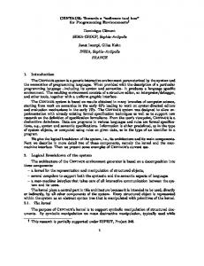
Fig. 1: Agents and cooperation between them. Based on the discussion in Section 3, as shown in Fig. 1, a set of distinguished agents have been defined in consideration of the effects of agent dimensions for efficiency of system. In the proposed approach, the local autonomy is assigned to application domains and interfaces. The cooperation between them is shown in virtue of UML collaboration diagram. Collaboration Controller Agent (CCA) is the global manager which coordinates the behaviors between user and system and inter-agents negotiations. Design Mediator Agent (DMA) and Machining Mediator Agent (MMA) have the ability to exchange information between application domains which they represent and the other agents. Database Mediator Agent (DbMA) is in charge of database management. Feature Recognition Agent (FRA) and Process Planning Agent (PPA) are responsible for the corresponding functions and communicating with the other agents. Adopting extended UML sequence Computer-Aided Design & Applications, 10(4), 2013, 603-618 © 2013 CAD Solutions, LLC, http://www.cadanda.com
608
diagram [39], the details of cooperation between agents in case of design change propagation are shown in Fig. 2. In Fig. 2, some non-essential communication activities, such as user login and user logoff, are omitted. The main procedure of design change propagation is as follows: 1.
Retrieve design feature model (DFM). The user informs CCA of the invoke request to DFM. CCA tells DMA to access database via DbMA. Then, the DFM is shown for user.
2.
CCA informs both DMA and MMA of design change. After having completed change to DFM, CCA tells both DMA and MMA that the DFM has been changed.
3.
MMA updates machining feature model (MFM). After learning of the change to DFM, the MMA contacts with FRA to re-recognize DFM for updating MFM.
4.
The user verifies updated MFM.
5.
Regenerate tool paths and store verified DFM as well as MFM in database. Once the updated MFM is verified by the user, the MMA gets machining process from PPA, and activates machining features to regenerate tool paths. Finally, both updated DFM and MFM are stored in database.
Fig. 2: The cooperation between agents in case of design change propagation. Computer-Aided Design & Applications, 10(4), 2013, 603-618 © 2013 CAD Solutions, LLC, http://www.cadanda.com
609 5
FEATURE-BASED AGENT-DRIVEN TOOL PATH GENERATION
As described in Section 3, machining features are implemented with object-oriented technology; they are not capable of making decision autonomously. The generation of machining feature model and its associated machining process are achieved by peer to peer communication between agents automatically. The feature-based agent driven tool path generation process is divided into three steps: Step 1: The machining feature model is obtained by feature recognition. Feature recognition algorithm use the method proposed in [1]. Step 2: The machining process is generated by process planning. The process planning method is not the topic of this paper, and can be found in [31]. Step 3: MMA activates machining features to generate tool paths with process parameters assigned by PPA. The tool path generation is realized through using API provided by CAD/CAM software. 5.1
Tool Path Regeneration for Design Change
A multi-layer pocket shown in Fig. 3 that frequently appears in aircraft structural parts is used to illustrate different types of design change.
Fig. 3: Multi-layer pocket with partial face and edge notations. It can be appreciated that tool path generation is driven by the machining process parameters and the drive geometries. The process parameters are assigned by Process Planning Agent whilst the drive geometries are created by machining feature itself. Fig. 4 shows how the side walls of the multi-layer pocket are machined. The yellow loops are the drive geometries.
Fig. 4: Tool paths of side machining of multi-layer pocket. The tool path generation logic is embedded in machining features, and machining features use constraint graph to store the identification process of drive geometries [40], as shown in Fig. 5. The Computer-Aided Design & Applications, 10(4), 2013, 603-618 © 2013 CAD Solutions, LLC, http://www.cadanda.com
610
constraint graph describes the relationships between constraints and variables explicitly as well as the generation processes of constraints. The generation processes of constraints accompany the knowledge-based reasoning processes. Therefore, it establishes the associations between constraints and knowledge, and is useful for change propagation. The classification of design changes falls into two categories: part level and feature level. In part level, the number or types of machining features alters. In feature level, the attributes or topological structures of machining features varies. The details of possible types of design changes at part and feature levels are listed in Table 1 and Table 2.
Fig. 5: Constraint graph and logic of drive geometries creation of layer1. When part level design changes happen, machining process alters. PPA renews the machining process, such as adding new machining operations, deleting existing machining operations and adjusting the sequence of machining operations. The tool path generation only occurs with new machining operations. The generation of machining operations accompanies the establishment of new constraint graphs. Table 1: Part level design change. Design change: Part level Item
Add new machining feature
1
●
2 3
●
Delete existing machining feature
Change machining process ●
●
●
●
●
Computer-Aided Design & Applications, 10(4), 2013, 603-618 © 2013 CAD Solutions, LLC, http://www.cadanda.com
611
Table 2: Feature level design change. Design change: Feature level Item
Change attributes Geometrical
1
●
2
●
Non-geometrical
Inter-features
Example
Fig. 6
3 4
●
6
Intro-feature
Change machining process ●
●
5
Change topological structure
Fig. 7
● ● ●
●
Fig. 8
●
Fig. 11, Fig. 12
Feature level design changes are mainly distinguished according to either feature attributes changes or feature topological structure changes. Feature attributes changes include geometrical attributes change (height of a pocket, diameter of a hole, etc.) and non-geometrical attributes change (material properties, surface finish, etc). In this research, features are represented and stored by holistic attribute adjacency graph (HAAG) [1]. HAAG extends the attributes’ information, and adds node types based on a traditional attribute adjacency graph. It not only represents freeform surface features, but also describes geometric information of topology elements precisely and completely. Evidently, feature topological structure changes mean that the HAAGs of features alter, which leads to constraint graphs’ evolvement.
Fig. 6: Attribute change doesn’t lead to machining process change.
Fig. 7: Attribute change leads to machining process change. When No.1-No.4 changes shown in Table 2 occur, the constraint graphs of drive geometries creations do not change, the machining features just need to re-execute the geometry manipulations to update the drive geometries. In particular, although the constraint graphs of drive geometries do not change, the corresponding machining process may alter. The radius of corner decreases from 12.5mm Computer-Aided Design & Applications, 10(4), 2013, 603-618 © 2013 CAD Solutions, LLC, http://www.cadanda.com
612
to 6mm, as shown in Fig. 7. It creates a new machining operation associated new cutter. As long as the type of machining operation does not change, the machining operation inherits the original constraint graph.
Fig. 8: Intro-feature topological structure change. Topological structure changes arises intro-feature or inter-features. An intro-feature topological structure change is shown with Fig. 8 (before) and Fig. 9 (after). The constraint graph of the drive geometries has changed, and then the machining feature reacts to this change via updating its topological structure. The machining feature regenerates tool paths through the same logic as shown in Fig. 10.
Fig. 9: Graph representation of intro-feature topological structure change. Inter-features topological structure changes lead to the attributes or machining operations change of the other feature, a case is shown with Figs. 11 (before) and 12 (after). In this case, the feature interactions arise. Feature interactions cause multiple interpretations which involve changes of machining operations and their sequence [41, 42]. In Fig. 11, the topological structure of multi-layer Computer-Aided Design & Applications, 10(4), 2013, 603-618 © 2013 CAD Solutions, LLC, http://www.cadanda.com
613
pocket feature has changed, which leads to the concurrent change of the depth of hole1 feature. Both hole1 and the multi-layer pocket features need update their tool paths. In Fig. 12, the topological structures of hole1 feature and multi-layer pocket feature change simultaneously. Because the access face of hole has been changed to inclined plane, the depth of hole1 has been changed and it should be machined before pocketing.
Fig. 10: Constraint graph and drive geometries of intra-feature topological structure change.
Fig. 11: Inter-features topological structure change cause change of machining operation.
Computer-Aided Design & Applications, 10(4), 2013, 603-618 © 2013 CAD Solutions, LLC, http://www.cadanda.com
614
Fig. 12: Inter-features topological structure change cause change of machining sequence. 5.2
Tool Path Regeneration for Process Changes
Besides design changes, machining process changes could arise due to the following reasons: machine change, tool change, process parameters change and machining sequence change. Because they do not involve topological structure changes of machining features, therefore the drive geometries do not change either. Consequently, the tool paths only need to be regenerated to reflect such changes. 6
CASE STUDY
A prototype feature-based tool path generation system for finish machining has been developed based on CATIA V5R18. An example airplane frame part is shown in Fig. 13 to verify the proposed method. This part has 9 pockets, 5 holes, 10 ribs and 1 outer profile. The details of its finish machining process are shown in Table 3. It needs 7 cutters to create 131 machining operations. On the average, each machining operation require user interactions by means of mouse and keyboard 20 times. The comparative results are shown in Table 4. Fig. 14 (a) shows the tool paths of a multi-layer pocket for side machining. When design change happens, the tool paths regenerate automatically as shown in Fig. 14 (b). In comparison with the tool paths generation manually, the efficiency is improved significantly.
Fig. 13: Aircraft structural part.
Computer-Aided Design & Applications, 10(4), 2013, 603-618 © 2013 CAD Solutions, LLC, http://www.cadanda.com
615
Fig. 14: Tool path regeneration before and after design change. Table 3. The details of finish machining process Sequence
Cutter
Machining feature
Number of machining operations
1
D20R0
Hole
2
2
D12R0
Hole
3
Rib
10
Pocket: bottom
18
Pocket: side
17
Pocket: bottom
1
Pocket: side
1
3
D20R3
4
D12R3
5
D12R3
Pocket: corner
48
6
D10R3
Pocket: corner
12
7
D20R0
Outer profile
1
Table 4. The Comparative Results
7
Method
Number of user interactions
Auxiliary geometries creation
Programming time
Programming manually
2620
Manually
At least 120 minutes
Programming with the proposed prototype system
5
Automatically
15 minutes
CONCLUSIONS
This paper presents a feature-based agent-driven automatic NC tool path generation method to meet the requirement of aircraft structural part dynamic manufacturing environment. In this research work, well-defined machining features are implemented which associate engineering knowledge, tool path generation and the related processes together. Machining features are activated by agents to make the proper responses for updating tool path automatically. Agents are also used to implement a collaboration controller, distinguished function services and domain mediators to propagate design and Computer-Aided Design & Applications, 10(4), 2013, 603-618 © 2013 CAD Solutions, LLC, http://www.cadanda.com
616
process changes to machining features. A preliminary prototype for feature-based tool path generation has been developed and the method works well. ACKNOLEDGEMENTS The authors would like to express their sincere thanks for the financial support by National Natural Science Foundation Project of China (50905087), Aeronautical Science Foundation Project of China (2010ZE52057), National Science and Technology Major Project of China (2012ZX04010-041), Funding of Jiangsu Innovation Program for Graduate Education (CXZZ11_0225) and Natural Science Foundation Project for Colleges and Universities in Jiangsu Province of China (10KJB460003). Dr. Yongsheng Ma also would like to acknowledge the support of Canada NSERC discovery grant (No. 355454-09) and Dr. Ma’s start-up grant from the University of Alberta. REFERENCES [1]
[2] [3]
[4]
[5]
[6] [7]
[8] [9] [10]
[11]
Li, Y. G.; Ding, Y. F.; Mou, W. P.; Guo, H.: Feature recognition technology for aircraft structural parts based on a holistic attribute adjacency graph, Proceedings of the Institution of Mechanical Engineers, Part B: Journal of Engineering Manufacture, 224(2), 2010, 271-278. DOI: 10.1243/09544054jem1634 Bronsvoort, W. F.; Noort, A.: Multiple-view feature modelling for integral product development, Computer-Aided Design, 36(10), 2004, 929-946. DOI: 10.1016/j.cad.2003.09.008 Sridharan, N.; Shah, J. J.: Recognition of Multi-Axis Milling Features: Part II—Algorithms & Implementation, Journal of Computing and Information Science in Engineering, 5(1), 2005, 25-34. DOI: 10.1115/1.1846054 Elkott, D. F.; Elmaraghy, H. A.; Elmaraghy, W. H.: Automatic sampling for CMM inspection planning of free-form surfaces, International Journal of Production Research, 40(11), 2002, 2653-2676. DOI: 10.1080/00207540210133435 Ma, Y. S.; Chen, G.; Thimm, G.: Paradigm shift: unified and associative feature-based concurrent and collaborative engineering, Journal of Intelligent Manufacturing, 19(6), 2008, 625-641. DOI: 10.1007/s10845-008-0128-y Bronsvoort, W. F.; Bidarra, R.; Nyirenda, P. J.: Developments in Feature Modelling, Computer Aided Design and Applications, 3(5), 2006, 655-664. DOI: 10.3722/cadaps.2006.655-664 Sridharan, N.; Shah, J. J.: Recognition of Multi Axis Milling Features: Part I-Topological and Geometric Characteristics, Journal of Computing and Information Science in Engineering, 4(3), 2004, 242-250. DOI: 10.1115/1.1778718 Gupta, R. K.; Gurumoorthy, B.: Automatic extraction of free-form surface features (FFSFs), Computer-Aided Design, 44(2), 2012, 99-112. DOI: 10.1016/j.cad.2011.09.012 Wang, J.; Wang, Z.; Zhu, W.; Ji, Y.: Recognition of Freeform Surface Machining Features, Journal of Computing and Information Science in Engineering, 10(4), 2010, 041006. DOI: 10.1115/1.3527075 Li, W. D.; Ong, S. K.; Nee, A. Y. C.: A hybrid method for recognizing interacting machining features, International Journal of Production Research, 41(9), 2003, 1887-1908. DOI: 10.1080/0020754031000123868 Rahmani, K.; Arezoo, B.: Boundary analysis and geometric completion for recognition of interacting machining features, Computer-Aided Design, 38(8), 2006, 845-856. DOI: 10.1016/j.cad.2006.04.015
Computer-Aided Design & Applications, 10(4), 2013, 603-618 © 2013 CAD Solutions, LLC, http://www.cadanda.com
617
[12]
[13]
[14]
[15]
[16] [17]
[18]
[19]
[20] [21] [22]
[23] [24] [25] [26]
[27]
[28]
Verma, A. K.; Rajotia, S.: A review of machining feature recognition methodologies, International Journal of Computer Integrated Manufacturing, 23(4), 2010, 353-368. DOI: 10.1080/09511921003642121 Babić, B. R.; Nešić, N.; Miljković, Z.: Automatic feature recognition using artificial neural networks to integrate design and manufacturing: Review of automatic feature recognition systems, Artificial Intelligence for Engineering Design, Analysis and Manufacturing, 25(03), 2011, 289-304. DOI: 10.1017/s0890060410000545 ElMaraghy, H. A. Reconfigurable Process Plans For Responsive Manufacturing Systems. In: Cunha, P. F.; Maropoulos, P. G., editors. Digital Enterprise Technology, New York, USA, Springer-Verlag, 2007, 35-44. DOI: 10.1007/978-0-387-49864-5_4 Kafashi, S.: Integrated setup planning and operation sequencing (ISOS) using genetic algorithm, The International Journal of Advanced Manufacturing Technology, 56(5-8), 2011, 589-600. DOI: 10.1007/s00170-011-3202-0 Azab, A.; ElMaraghy, H. A.: Mathematical Modeling for Reconfigurable Process Planning, CIRP Annals - Manufacturing Technology, 56(1), 2007, 467-472. DOI: 10.1016/j.cirp.2007.05.112 Zhang, Y.; Ge, L.: Selecting optimal set of tool sequences for machining of multiple pockets, The International Journal of Advanced Manufacturing Technology, 42(3-4), 2009, 233-241. DOI: 10.1007/s00170-008-1609-z Banerjee, A.; Feng, H. Y.; Bordatchev, E. V.: Process planning for corner machining based on a looping tool path strategy, Proceedings of the Institution of Mechanical Engineers, Part B: Journal of Engineering Manufacture, 225(9), 2011, 1578-1590. DOI: 10.1177/0954405411401687 Rauch, M.; Hascoet, J.-Y.: Selecting a milling strategy with regard to the machine tool capabilities: application to plunge milling, The International Journal of Advanced Manufacturing Technology, 59(1-4), 2012, 47-54. DOI: 10.1007/s00170-011-3498-9 Altintas, Y.; Weck, M.: Chatter Stability of Metal Cutting and Grinding, CIRP Annals Manufacturing Technology, 53(2), 2004, 619-642. DOI: 10.1016/S0007-8506(07)60032-8 Spence, A. D.; Altintas, Y.: A Solid Modeller Based Milling Process Simulation and Planning System, Journal of Engineering for Industry, 116(1), 1994, 61-69. DOI: 10.1115/1.2901810 Weck, M.; Altintas, Y.; Beer, C.: CAD Assisted Chatter-free NC Tool Path Generation in Milling, International Journal of Machine Tools and Manufacture, 34(6), 1994, 879-891. DOI: 10.1016/0890-6955(94)90066-3 Heo, E. Y.; Merdol, D.; Altintas, Y.: High Speed Pocketing Strategy, CIRP Journal of Manufacturing Science and Technology, 3(1), 2010, 1-7. DOI: 10.1016/j.cirpj.2010.06.006 Smith, S.; Dvorak, D.: Tool path strategies for high speed milling aluminum workpieces with thin webs, Mechatronics, 8(4), 1998, 291-300. DOI: 10.1016/S0957-4158(97)00058-5 Smith, S.; Woody, B.; Ziegert, J.; Huang, Y.: Deformation Machining - A New Hybrid Process, CIRP Annals - Manufacturing Technology, 56(1), 2007, 281-284. DOI: 10.1016/j.cirp.2007.05.065 Harik, R. F.; Derigent, W. J. E.; Ris, G.: Computer Aided Process Planning in Aircraft Manufacturing, Computer-Aided Design and Applications, 5(6), 2008, 953-962. DOI: 10.3722/cadaps.2008.953-962 Villeneuve, F.; Brissaud, D.; Zirmi, O.; Capponi, V.: Computer Aided Process Planning, Strategy, and Models in the Aircraft Industry, Proceedings of the Institution of Mechanical Engineers, Part B: Journal of Engineering Manufacture, 220(4), 2006, 541-553. DOI: 10.1243/095440505x32887 Xu, X.; Wang, L.; Newman, S. T.: Computer-aided process planning – A critical review of recent developments and future trends, International Journal of Computer Integrated Manufacturing, 24(1), 2011, 1-31. DOI: 10.1080/0951192x.2010.518632 Computer-Aided Design & Applications, 10(4), 2013, 603-618 © 2013 CAD Solutions, LLC, http://www.cadanda.com
618
[29]
[30]
[31]
[32]
[33]
[34]
[35] [36]
[37] [38] [39]
[40] [41]
[42]
Zhang, L.; Deng, J.; Chan, S. C.-F.: A Next Generation NC Machining System Based on NC Feature Unit and Real-Time Tool-Path Generation, The International Journal of Advanced Manufacturing Technology, 16(12), 2000, 889-901. DOI: 10.1007/s001700070007 Hou, M.; Faddis, T. N.: Automatic tool path generation of a feature-based CAD/CAPP/CAM integrated system, International Journal of Computer Integrated Manufacturing, 19(4), 2006, 350-358. DOI: 10.1080/09511920500504354 Li, Y. G.; Fang, T. L.; Cheng, S. J.; Liao, W. H.: Research on Feature-Based Rapid Programming for Aircraft NC Parts, Applied Mechanics and Materials, 10-12, 2008, 682-687. DOI: 10.4028/www.scientific.net/AMM.10-12.682 Xu, X. W.; Wang, L.; Rong, Y.: STEP-NC and function blocks for interoperable manufacturing, IEEE Transactions on Automation Science and Engineering, 3(3), 2006, 297-308. DOI: 10.1109/TASE.2005.862147 Cuenca, S.; Jimeno-Morenilla, A.; Martínez, A.; Maestre, R.: Hardware approach to tool path computation for STEP-NC enabled CNC: A case study of turning operations, Computers in Industry, 62(5), 2011, 509-518. DOI: 10.1016/j.compind.2011.02.001 Kretz, D.; Teich, T.; Militzer, J.; Neumann, T.: Implementing ISO standard 10303 application protocol 224 for automated process planning, Robotics and Computer-Integrated Manufacturing, 27(4), 2011, 729-734. DOI: 10.1016/j.rcim.2010.12.010 Wang, L.; Shen, W.: DPP: An agent-based approach for distributed process planning, Journal of Intelligent Manufacturing, 14(5), 2003, 429-439. DOI: 10.1023/A:1025797124367 Salmon, J.; Jacquel, D.: Design for manufacturability: a feature-based agent-driven approach, Proceedings of the Institution of Mechanical Engineers, Part B: Journal of Engineering Manufacture, 214(10), 2000, 865-879. DOI: 10.1243/0954405001517955 Ma, Y. S.; Tong, T.: Associative feature modeling for concurrent engineering integration, Computers in Industry, 51(1), 2003, 51-71. DOI: 10.1016/s0166-3615(03)00025-3 Villa, A.: Autonomy versus efficiency in multi-agent management of extended enterprises, Journal of Intelligent Manufacturing, 13(6), 2002, 429-438. DOI: 10.1023/A:1021089726811 Bauer, B.; Müller, J. P.; Odell, J.: Agent UML: A Formalism for Specifying Multiagent Software Systems, International Journal of Software Engineering and Knowledge Engineering, 11(3), 2001, 207-230. DOI: 10.1063/1.2957976 Lin, L.; Chen, L. C.: Constraints modelling in product design, Journal of Engineering Design, 13(3), 2002, 205-214. DOI: 10.1080/0954482011010890 Regli, W. C.; Pratt, M. J. What are feature interactions? The 1996 ASME Design Engineering Technical Conference and Computers in Engineering Conference; August 18-22, 1996, Irvine, California, USA, ASME, 1996. DOI: 10.1.1.160.6597 Dipper, T.; Xu, X.; Klemm, P.: Defining, recognizing and representing feature interactions in a feature-based data model, Robotics and Computer-Integrated Manufacturing, 27(1), 2011, 101-114. DOI: 10.1016/j.rcim.2010.06.016
Computer-Aided Design & Applications, 10(4), 2013, 603-618 © 2013 CAD Solutions, LLC, http://www.cadanda.com
Copyright of Computer-Aided Design & Applications is the property of Computer-Aided Design & Applications and its content may not be copied or emailed to multiple sites or posted to a listserv without the copyright holder's express written permission. However, users may print, download, or email articles for individual use.