Electronic Notes in Theoretical Computer Science 51 (2002) URL: http://www.elsevier.nl/locate/entcs/volume51.html 13 pages
Towards a Formal Framework for Inter-Enterprise Application Integration ? Reiko Heckel 1 Gregor Engels 2 Dept. of Mathematics and Computer Science University of Paderborn D-33095 Paderborn, Germany
Abstract A major concern of software development today is the integration of applications of different enterprises, e.g., over the internet. This requires a shift of focus from system development towards integration of enterprise models and evolution of systems. We propose a conceptual framework for a method addressing these issues and discuss its formalization by means of graph transformation concepts. Key words: inter-enterprise application integration, graph transformation, business modeling, system modeling, evolution
1
Introduction
One of the major challenges for software engineering today is the integration of applications over the internet. E-commerce or e-business applications, for example, combine services of different enterprises to yield one integrated product. Thereby, boundaries between different data formats, computational platforms, and administrative domains have to be bridged because, typically, the applications have been developed under different authorities using different process models, methodologies, and tools. A major concern is, therefore, to achieve consistency between the different (sub)systems. The problem occurs at different levels, like •
the level of application logic concerned with business objects like bills, accounts, and customers as well as business processes, like the payment of bills or the opening of accounts
? Research partially supported by the ESPRIT Working Group APPLIGRAPH and the TMR network GETGRATS. 1 Email:
[email protected] 2 Email:
[email protected]
c 2002 Published by Elsevier Science B. V. °
Heckel and Engels •
the level of software architecture concerned with application components, like an e-banking server of a banking system and the corresponding client at the customer’s desktop computer, and the application protocols by which the components communicate
•
the level of system architecture concerned with system components like data bases, web servers, etc., their interaction and deployment on the actual machines
One of the main approaches to achieve consistency at all levels is to start with a model which represents an abstraction from both implementation details and irrelevant aspects of the real world. As shall be explained in more detail below, such a model can be used to represent the present situation (before the integration) or the intended situation afterwards. With the help of models, many inconsistencies and conflicts between the views of different enterprises can be resolved simply by raising the level of abstraction and concentrating on the conceptual problems before dealing with implementation issues. The (in)consistency of views has been an issue of view-based development approaches like [9,14]. Here we have to distinguish between inconsistencies in the development process and between different components of the running system. While the first kind of inconsistency is a normal fact of system development which has to be accepted and dealt with, e.g., by bookkeeping of conflicts until they are resolved, inconsistencies in the running system lead to continuous effort for maintainance and error handling and should be avoided. In this paper we are interested in this second kind of consistency. Especially at the level of application logic, consistency problems cannot be solved by computer scientists alone because the very basic concepts and processes of an enterprise are involved. Thus it requires negotiations among domain experts, computer scientists, and users from both enterprises to detect semantic relations and conflicts between the corresponding concepts. For this purpose, a language is needed which is abstract (so that it does not force to deal with low-level detail), intuitive (so that it is understandable to noncomputer scientists), and precise (in order to allow to detect inconsistencies and errors between the views of different enterprises). Object oriented modeling languages like the UML [18] fulfill the first two requirements, i.e., they provide a high-level, intuitive notation to express all the relevant aspects. However, they do not, in general, allow for precise specifications unless a specific semantic interpretation is employed. Moreover, the meaning of a model depends on the abstraction level, scope, and context of the model, i.e., its role in the overall development process. Thus, a modeling approach for inter-enterprise application integration (and in general) requires both a formal foundation and a clear conceptual framework which makes precise the different roles models can play, as well as the relationships between these roles. 2
Heckel and Engels
In this paper, these issues will be discussed at the level of requirement specification (concerned with the application logic) because, for the abovementioned reasons, here the use of models is most effective. After introducing the conceptual framework in the following section, in Section 3 to 6 the different dimensions and resulting roles are sketched and references are given for possible formalizations. In Section 7, open problems are summarized.
2
Inter-Enterprise Application Integration
Mainstream UML-based development processes like the Unified Process [15] or Catalysis [6] structure the early stage of development into activities like (i) business modeling, that is, building a model that explains the present concepts, documents, and processes of the enterprise without making reference to any existing software system (ii) requirement specification, i.e., stating the intended properties of the system to be developed without making decisions about how it shall be realized The simplifying assumption here (of which the cited approaches are aware) is that the task consists in developing a system from scratch, and that the overall operation of the enterprise (the business model) does not change. In fact, from the two descriptions, the following two dimensions can be derived. business vs. system model that is, do we model all concepts and processes relevant to the operation of the enterprise, or do we restrict ourselves to those actually supported by a software system before vs. after model i.e., does the model describe the present situation (before the current development effort) or the (intended) situation afterwards With this terminology, item 1 above deals with the business model/before while item 2 is concerned with the system model/after. Naturally, if the task consists in integrating different applications, the existence of these applications before the current development effort is an issue of high relevance, while the evolution of the business itself may or may not be important. A major additional dimension, particular to the integration problem, is local vs. global i.e., the scope of the model which may be concerned with the view of one or the other enterprise, the intersection of these views, or the integrated view. On this basis, a process for inter-enterprise application integration (and in general [24]) can be seen as a way of navigating through the three- (or more-) dimensional space, visiting certain points in a pre-defined order. More precisely, each point defines a potential role of a model in the development 3
Heckel and Engels b a ` _ ^ ] \ [ Y X f e d W+ 1 B0 @ ~ U** @@@ ~ ** @ ~ ~ ** @@ ~ ~ ** @@@ @ ~]~ \ ~~ * _ _ @ ^ ^ ~ ~ ` ` ] a a \ b b [ [ * Ã ~~ ~~ Y** X W@Ã e d Y X W+ e d * f + 1 g 1 0g f 0 ** ** B1U* B B2U* B1U* B B2U* * * B B ** BB ** BB ** }}} ** ** }}} ** ** * BB * ** BBB }}* }}* BÃ ~}}} ** e d b** a ` _ ^ ] \ [ Y** X BBÃ ~}}} ** ** ** f ** W+ 1 ** ** ** 0g ** ** B U* B U* ** ** ** ** ** ** ** ** * * ** ** ** ** ** ** ** ** *' *' _ ^ ]* \ [ Y* ** ** ** G G g f ** e d b a ` ** ** X W+ 1 0 ** * ** ** S S * * ** ~ 0 @@ ** ** ~ 0 @@ *** ** ** @@ * @@ * *~* ~~ *~* ~~ * ** @@ * @ * *' ~ ~~~ ** d b a @`@Â **' _ ^ ] \ [d b a ` **' _ ^~ ~~~]** \ [ Y X W@Â ' G Y X W G ~ * G g f e G g~ f * e + 1 + 1 0 0 * * S2 S1 B * S2 S1 B * BB ** BB ** } } }} B BB * } } BB ** BB ** }} }} BÃ ' G ~}}} e d b a ` _ ^ ] \ [ Y X BBÃ *' G ~}}} W+ g f
B00U* g@
S0
S1
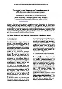
Fig. 1. A framework for inter-enterprise application integration
process, and for each particular process one has to define both the roles that actually have to be filled by models and the order in which this shall be done. The benefit of considering such a multi-dimensional conceptual framework independently of the actual development process is the possibility of having pre-defined relations between these roles which give rise to consistency conditions between different models. (For example, a system model should always be a reduction of the corresponding business model (if we fix all other dimensions), independently of the order in which they are produced.) The different dimensions and roles of the framework and their relations are visualized in the diagram in Fig. 1 as follows. The dimension of business model Bij vs. system model Sij is shown vertically. The arrows Bij ←- Sij shall describe the idea that a system model is a reduction of the corresponding business model. The transition between the situation before and after the development is represented horizontally by dashed arrows from Xi0 to Xi1 . The integration of models of different enterprises is expressed by the four diamonds between vertices X0i , X1i , X2i and X i . Here, X1i and X2i represent the two local enterprise models, X0i a common view of the two, and X i a correspondingly integrated model. Based on these notions, a typical development process for inter-enterprise application integration can be described. For simplicity (and in order to prepare the example presented later) we assume that the task consists in the integration of two local software systems while preserving the actual business processes. Therefore, the evolution will only take place at the level of the system model. In general, however, as shown in the diagram of Fig 1 our framework accommodates evolution at both levels. (i) Reverse engineering: The business and system models B10 ←- S10 and B20 ←- S20 are produced based on an analysis of the actual situation in 4
Heckel and Engels
both enterprises. (ii) Integration of business models: The two local business models B10 and B20 are integrated. This requires to build a reference model B00 which represents the shared concepts and operations of both local views, and an integrated model B 0 based on the common reference model. (iii) Integration of system models: In analogy to the business model, the local system models S10 and S20 are integrated over the reference model S00 to S 0 . It has to be verified that S0 is indeed a reduction of B 0 , i.e., the relation B 0 ←- S 0 has to be established. (iv) Evolution of integrated system model: In this activity, the integrated system model S 0 , which represents a global view of the two systems before the actual development shall be transformed into a requirement specification S 1 for the integrated system afterwards. Since the business model is preserved (i.e., B 0 = B 1 ) we have to verify that this new system model S 1 is still a reduction of the business model. (Thus, all that actually happens is an extension of the scope of the system supporting concepts and tasks that have been dealt with manually before.) (v) Projection and analysis of local evolution: The global model for the integrated system has to be projected onto the two local views in order to understand the local changes required. Thus, the models S11 , S21 are produced as well as their evolution relations to the models S10 , S20 . Again, the reduction relation with B11 = B10 and B21 = B20 has to be verified. In the following four sections, we will give some small examples for the different models and their relationships and make reference to possible formalizations. However, before the three dimensions of our framework, the internal structure of each of the models shall be explained, which may be seen as a fourth orthogonal dimension.
3
Static, Dynamic, and Functional Aspect
All models are composed of three submodels representing, respectively, the static, dynamic, and functional aspect. Employing UML notation, the static aspect is given by a class diagram. Since we are at the level of requirement specification, classes do not have method signatures associated with them, i.e., the class diagram specifies only classes, associations, attributes, and constraints [15,6]. The dynamic model specifies business processes (within or outside the system) by means of activity diagrams consisting of action states (oval vertices) which are connected by transitions modeling the flow of control (solid arcs) and/or objects (dashed arcs). In addition, notations for choice (diamonds), and fork/join (horizontal bars) are provided [18]. The functional aspect describes pre/post conditions and effects of actions by means of (pairs of) instance diagrams interpreted as transformation rules [6]. The model given in Fig. 2 exemplifies the three aspects. It represents the 5
Heckel and Engels
Static Model BankAccount
Dynamic Model
LegalEntity
has
accNo
enter Bill
name
blz hand over Bill to
Shop
after two weeks
Client
issues
check BankAccount
pays
Bill
Product
total
record payment
prize
status
after one week
[transfer
[no transfer
received]
received]
send warning
contains
Functional Model
:Shop
issues
b:Bill
b:Bill
total = x
hand over Bill
status = closed
issues
total = x
:Shop
status = sent pays
:Client
:Client
Fig. 2. The business model of a shop (role B10 )
local business model of a shop which shall play the role B10 in our framework. Notice that such a model is not object-oriented in the classical sense because there is no association of actions with objects. In the cited OO process models, this association happens later in the analysis phase. Formally, the static and functional submodels jointly form a typed graph transformation system [5] based on attributed graphs [17]. An activity diagram can be seen as a notational variant of a (high-level) Petri net (see, e.g., [10]). Augmented with appropriate application conditions, attributed graph transformation can encode Petri nets—thus a formal integration of the three aspects should be straightforward.
4
Model Integration
When integrating two models that have been developed separately, we face two different problems: the variation of scope and the incompatibility of representations. Variation of scope means that the fragment of the world described by a model is enlarged or reduced when moving from a local to a more global point of view, or vice versa. Thus, when integrating two views, we first have to understand the intersection of their scopes before we can actually merge them. This is the motivation for considering, in our conceptual framework, the reference model X0i . Once this model is built and related to the two local 6
Heckel and Engels
Static Model
LegalEntity
uses
Account
from Order
number
name
balance
to
provides Bank Shop
Client
executes
concerns Product
Bill
blz pays
Clerk name
amount
status
contains prize
issues
Functional Model :Bill
:Order status = sent concerns pays :Client
uses
complete Order form
:Clerk
:Account
:Order
:Order
:Account
amount = x
amount = x
balance = x
concerns
hand over Bill
concerns
:Bill
:Bill
status = closed
status = closed issues
issues :Shop
:Client
:Shop
executes :Clerk
pays :Client
:Account balance = y
:Bill
:Clerk :Order status = sent executes concerns from pays uses :Client :Account
:Account
from
balance = x-a do Transfer :Order amount = a
to
:Clerk
:Account balance = y+a
Fig. 3. Integrated business model of shop and bank (static and functional aspect of role B 0 )
views X1i and X2i , the intersection is fixed and the integration can be done (more or less) automatically [8]. Building the reference model, we face the problem of incompatible representations: Models of independent enterprises are likely to use different names for similar concepts, or the same names for concepts which are semantically different. More dramatically, representations may be incomparable (e.g., because the same concept is modeled in two different ways using classes and associations). These conflicts have to be resolved in the reference model by choosing one or the other representation or proposing a more general one. Moreover, mappings have to be specified from the local representations to the corresponding ones in the reference model. An integrated business model, filling role B 0 of our framework, is shown in Fig. 3 and 4. It represents the integration of the model in Fig. 2 with the business model of a bank (not given in the paper). Notice the different representations, e.g., of bank accounts which are modeled as single objects in the local shop view while they are represented by two different (but related) objects in the global model. A similar refinement occurs in the case of bills. The extension of the scope from the local to the global view is exemplified, e.g., by additional concepts like Clerk, which do not have a correspondence in the local view. 7
Heckel and Engels
Dynamic Model Shop
Bank
enter Bill
:Order complete Order form
hand over Bill
after 2 weeks check BankAccount
enter Order form [amount not avail.]
:Bill
notify Customer
[amount avail.]
do Transfer
...
Fig. 4. Integrated business model of shop and bank (dynamic aspect of role B 0 ))
The integration of conflicting static models of different views into a single consistent overall model has been studied in depth in the area of data base design [2,22,4]. In order to describe the mapping between the two views at the level of instances, the most promising approach seems to be that of triple graph grammars [21] which allows the generation of bi-directional translators out of correspondence rules. In the functional view, we notice two additional rules, one originating from the banking model and the other one (complete order form) providing a link between the two businesses as shown in the dynamic submodel in Fig. 4. In particular, the interaction of the functional submodels of two views has been studied in depth in a series of papers on views and view integration based on open graph transformation systems (see, e.g., [8,13,11]). Assuming a semantic analogy between activity diagrams and Petri nets, the integration of dynamic submodels is the subject of [1].
5
Business vs. System Modeling
A business model specifies all (relevant) concepts, processes, and actions of an enterprise whereas a system model specifies only those that are actually supported by a software system. (In addition, the system model typically includes a specification of the users of a system, captured in a use case diagram. Use case diagrams can also help to distinguish different (sub)systems and to associate the main user actions (use cases) with the users and the (sub)systems performing them. In this paper, we ignore the user model and consider all local subsystems within the same enterprise as one integrated system.) 8
Heckel and Engels
Static Model
Dynamic Model
BankAccount
Client
accNo
name
enter Bill
blz to
printBill
pays
Bill
[transfer received]
Product
total
record Payment
prize
status contains
Functional Model b:Bill total = x
b:Bill
print Bill
status = closed
total = x status = sent pays
:Client
:Client
Fig. 5. The model of a cashbox system (role S10 )
The reduction from the business model to the system model is, again, a variation of the scope of the model, formally described as a view relation [8]. Notice that we allow renaming, but we do not consider refinement, i.e., the level of detail should not change. Fig. 5 shows the system model of a cashbox as reduction of the shop business model in Fig. 2. Notice that the class Shop has been removed from the static model (that is, the cashbox does not know about different shops). From the dynamic model, two actions (check account and warn customer) are removed because they are performed by the sales person without the cashbox’s assistance. The action hand over bill is replaced by print bill. In the functional model, the rules that are not omitted (because the corresponding actions are no longer present) have to be reduced to instances of the classes in the corresponding class diagram. For example, from the rule print bill, the Shop object has been removed.
6
Model Evolution
The evolution at the level of models anticipates the changes to the actual system or business. If, as in the example presented here, the business model is preserved, it provides a common context to the system model before and after the change, i.e., both system models are reductions of the same business 9
Heckel and Engels
Dynamic Model EBillingSystem
CashBox
Bank
enter Bill :Order
check Order
printBill complete Order form [transfer received] record Payment
[amount not avail.]
:Bill
notify Customer
[amount avail.]
do Transfer
Functional Model :Bill
:Order status = sent concerns pays :Client
uses
:Clerk
complete Order form
:Account
:Bill
:Clerk :Order status = sent executes concerns from pays uses :Client :Account
Fig. 6. Requirement specification for integrated system model (dynamic and functional aspect for role S 1 )
model. This shows the relevance of business modeling because, in this case, the evolution of the system model mainly consists in choosing among the processes and concepts of the business model those that shall be supported. For example, in Fig. 6 the dynamic and functional submodels of the global system model after the evolution are shown, filling role S 1 of the framework. The activity diagram is a reduction of the one in the integrated business model (Fig. 4) but for the fact that the action complete order form is now associated with an EBillingSystem, i.e., a system which allows customers to handle bills and corresponding bank transfers online. The associated rule coincides with the one in Fig. 4 but for the fact that the clerk is no longer involved. In general, also the business model will evolve, e.g., as a result of introducing new software. In this case, the relation between the models before and after the evolution could be expressed by a (possibly partial) mapping relating corresponding concepts. Such mappings can be obtained in different ways. •
Through model transformations, i.e., applying (in all submodels) pre-defined evolution rules. Formalizations of this idea are discussed, for example, in [20,3,19,16,7,12].
•
As instances of a declarative (e.g., logic-based) requirement specification for the target model.
•
By means of certain classes of homomorphisms between models that preserve or reflect important semantic properties. 10
Heckel and Engels
In general, one should distinguish between refactoring of the model (i.e., improving the model structure while preserving its semantic content) and the extension or refinement of concepts.
7
Conclusion
In this section, we want to point out the open semantic issues in the framework as a program of future work. A couple of things have to be worked out in more detail in order to arrive at a fully formal notion of model, like the relation between Petri nets and activity diagrams (formalizing the dynamic aspect) and between open (high-level) Petri nets and open (attributed) graph transformation systems (fixing the relation between the functional and the dynamic aspect). More or less open is the question, how to extend the view integration approach with a technique for mapping different representations of the same concept. We have mentioned triple graph grammars, but they are not yet incorporated in the notion of view discussed in [8]. An alternative, more general approach could be based on active constraints [23]. Similarly, a general notion of evolution including the business model is missing, although the cited rule-based approaches provide a good starting point.
References [1] P. Baldan, A. Corradini, H. Ehrig, and R. Heckel. Compositional modeling of reactive systems using open nets. In Proc. Concur 2001, Aarhus, August 2001. To appear. [2] C. Batini, M. Lenzerini, and S. Navathe. A comparative analysis of methodologies for database schema integration. ACM Computing Surveys, 18(6):323–364, 1986. [3] I. Claßen and M. L¨owe. Scheme evolution in object oriented models: A graph transformation approach. In Proc. Workshop on Formal Methods at the ISCE’95, Seattle (U.S.A.), 1995. [4] S. Conrad. F¨ oderierte Datenbanksysteme: Konzepte der Datenintegration. Springer-Verlag, 1997. [5] A. Corradini, U. Montanari, and F. Rossi. Graph processes. Fundamenta Informaticae, 26(3,4):241–266, 1996. [6] D. D’Souza and A. Wills. Components and Frameworks with UML: The Catalysis Approach. Addison-Wesley, 1998. [7] G. Engels and R. Heckel. Graph transformation as unifying formal framework for system modeling and model evolution. In Proc. ICALP 2000, LNCS, Geneva, Switzerland, July 2000. Springer-Verlag. http://www. uni-paderborn.de/cs/ag-engels/Papers/2000/EngelsIcalp00.pdf.
11
Heckel and Engels
[8] G. Engels, R. Heckel, G. Taentzer, and H. Ehrig. A combined reference model- and view-based approach to system specification. Int. Journal of Software and Knowledge Engeneering, 7(4):457–477, 1997. Preprint at http: //tfs.cs.tu-berlin.de. [9] A. Finkelstein, J. Kramer, B. Nuseibeh, M. Goedicke, and L. Finkelstein. Viewpoints: A framework for integrating multiple perspectives in system development. Int. Journal of Software Engineering and Knowledge Engineering, 2(1):31–58, March 1992. [10] T. Gehrke, U. Goltz, and H. Wehrheim. Zur semantischen Analyse der dynamischen Modelle von UML mit Petri-Netzen. In E. Schnieder, editor, Proceedings of The 6th Symposium on Development and Operation of Complex Automation Systems, 1999. [11] R. Heckel. Open Graph Transformation Systems: A New Approach to the Compositional Modelling of Concurrent and Reactive Systems. PhD thesis, TU Berlin, 1998. http://www.uni-paderborn.de/cs/ag-engels/Papers/1998/ HeckelPhD98.pdf. [12] R. Heckel and G. Engels. Graph transformation as a meta language for dynamic modeling and model evolution. In T. Mens and M. Wermelinger, editors, Int. Special Session on Formal Foundations of Software Evolution, Lisboa, Portugal, March 2001. Co-located with the European Conference on Software Maintainance and Reengineering (CSMR 2001). [13] R. Heckel, G. Engels, H. Ehrig, and G. Taentzer. A view-based approach to system modelling based on open graph transformation systems. In G. Engels, H.-J. Kreowski, and G. Rozenberg, editors, Handbook of Graph Grammars and Computing by Graph Transformation, Volume 2: Applications, Languages, and Tools. World Scientific, 1999. [14] ISO/IEC 10746 ITU-T X.901 X.904. Reference model of open distributed processing, 1994. [15] I. Jacobson, G. Booch, and J. Rumbaugh. The Unified Software Development Process. Addison Wesley, 1999. [16] M. L¨owe. Evolution patterns. Postdoctoral thesis, Technical University of Berlin. Tech. Report 98-4, Dept. of Comp. Sci, 1997. [17] M. L¨owe, M. Korff, and A. Wagner. An algebraic framework for the transformation of attributed graphs. In M.R. Sleep, M.J. Plasmeijer, and M.C. van Eekelen, editors, Term Graph Rewriting: Theory and Practice, chapter 14, pages 185–199. John Wiley & Sons Ltd, 1993. [18] Object Management Group. UML specification version 1.3, June 1999. http: //www.omg.org. [19] J. Padberg, H. Ehrig, and L. Ribeiro. Algebraic high-level net transformation systems. MSCS, 2:217–256, 1995.
12
Heckel and Engels
[20] F. Parisi Presicce. Transformation of graph grammars. In 5th Int. Workshop on Graph Grammars and their Application to Computer Science, Williamsburg ’94, LNCS 1073, 1996. [21] A. Sch¨ urr. Specification of graph translators with triple graph grammars. In Tinhofer, editor, Proc. WG’94 Int. Workshop on Graph-Theoretic Concepts in Computer Science, number 903 in LNCS, pages 151–163. Springer-Verlag, 1994. [22] S. Spaccapietra and C. Parent. View integration: A step forward in solving structural conflicts. IEEE Transactions on Software and Data Engineering, 6(2):258–274, 1994. [23] A.J. Winter and A. Sch¨ urr. Modules and updatable graph views for programmed graph rewriting systems. Technical Report 97-3, RWTH Aachen, FG Informatik, October 1997. [24] A. Zamperoni and G. Engels. Formal integration of software engineering aspects using graph rewrite systems - a typical experience?! In M. Nagl and A. Sch¨ urr, editors, Proc. Applications of Graph Transformations With Industrial Relevance (AGTIVE), Kerkrade (The Netherlands), September 1–3, 1999, volume 1779 of LNCS. Springer-Verlag, 2000.
13