Many modern image processing applications (such as processing video and very large .... converters may be needed to convert between different representations (e.g. from bit serial to ..... http://www.cs.qub.ac.uk/~K.Benkrid/MyThesis.html.
Towards a General Framework for FPGA Based Image Processing using Hardware Skeletons K Benkrid, D Crookes and A Benkrid School of Computer Science, The Queen’s University of Belfast, Belfast BT7 1NN, UK (K.Benkrid, D.Crookes, A.Benkrid)@qub.ac.uk
Abstract In this paper, we present our approach to developing a general framework for FPGA based Image Processing. This framework is based on a library of Hardware Skeletons. A hardware skeleton is a parameterised description of a task-specific architecture. A skeleton’s implementation will apply optimisations specific to the target hardware.
The library
normally contains a range of alternative skeletons for the same task, perhaps tailored for different data representations. The library also contains high level skeletons for compound operations, whose implementation can apply appropriate optimisations. Given a complete algorithm description in terms of skeletons, an efficient hardware configuration is generated automatically.
We have developed a library of hardware skeletons for common image
processing tasks, with optimised implementations specifically for Xilinx XC4000 FPGAs. This paper presents and illustrates our hardware skeleton approach in the context of some common image processing tasks. It demonstrates our approach to the broader problem of achieving optimised hardware configurations while retaining the convenience and rapid development cycle of an application-oriented, high level programming model.
Keywords: FPGA, Coprocessor, Hardware Skeletons, Image Processing, High Level Programming.
1. Introduction Many modern image processing applications (such as processing video and very large images) are so computationally demanding that special purpose hardware solutions need to be considered. Reconfigurable hardware in the form of FPGAs can offer the performance advantages of a custom hardware solution, while their reprogrammability makes them multi-
1
purpose and reusable. However, a big disadvantage is the low level, hardware-oriented programming model needed to get the most from the FPGA’s potential performance. Despite the great amount of research done on FPGAs, many FPGA-based applications have been algorithm specific [1][2][3]. An environment for developing applications needs more than just a library of static FPGA configurations, perhaps parameterisable (e.g. in terms of input data wordlength), since it should allow the user to experiment with alternative algorithms and develop his/her own algorithms. There is a need for bridging the gap between high level application-oriented software and low level FPGA hardware. Many behavioural synthesis tools [4][5][6] have been developed to satisfy this requirement. These tools allow the user to program FPGAs at a very high level (e.g. in a C-like syntax) without having to deal with low level hardware details (e.g. scheduling, allocation, pipelining etc.). However, although behavioural synthesis tools have developed enormously [7][8], structural design techniques often still result in circuits that are substantially smaller and faster than those developed using only behavioural synthesis tools [9][10]. The aim of this work is to provide a framework for developing efficient hardware solutions specifically for image processing applications. This framework gives the benefits of an application-oriented, high level programming model, but does not sacrifice significantly the performance of the solution. Our approach to this is to use a concept which has proved relatively successful in developing parallel software, namely skeletons [11][12][13]. Skeletons are reusable, parameterised fragments or frameworks to which the user can supply components (e.g. functions). It is common for skeletons to include functions as parameters which are applied by the skeleton to a data set. The implementation of a skeleton is normally optimised for a specific target machine. In this paper we introduce the concept of hardware skeletons. A hardware skeleton is a parameterised description of a task-specific architecture, to which the user can supply parameters such as values, functions (parameterised functional blocks) or even other skeletons. In this sense, a skeleton is like a class, from which specific instances can be created. Certain combinations of basic skeletons can form the basis of additional, higher level skeletons. The concept grew up from our experience in Image Processing where we have noticed that many IP operations can be assembled using common arrangements of basic image operations on which known optimisations can be applied. Hardware skeletons are conceptually similar to Cole et al’s [11][12][13] software skeletons, although the intricacies of hardware implementation are inherently different from those in Software (e.g. buffer sharing, synchronisation of operations with different word lengths etc.). Considerable work 2
has been done on problems associated with multiple FPGA implementations (e.g. the ArMen project [14]). However, with current FPGA chips densities crossing the 10 million gates barrier, it is increasingly possible to implement very sophisticated algorithms on one FPGA chip. The work presented in this paper targets a single-chip FPGA machine. Other researchers have addressed the issue of dynamic reconfiguration (e.g. ARDOISE project [15]). Our current system targets Xilinx XC4000 FPGAs, which do not allow for dynamic reconfiguration. From a compilation point of view, our approach is different from any other work we are aware of. Indeed, the use of the notion of hardware skeletons, specific to the application domain in hand, is novel to the hardware domain. Also, the use of a rule-based language (Prolog) to apply task-specific optimisations as well as target-hardware-specific optimisations is novel. To illustrate this, the paper first identifies a suitable applicationoriented model for describing image processing operations. The common basic tasks which we identify will form the basis of a library of core skeletons. Next, we outline the strategy which the system employs to generate efficient FPGA configurations from a given operation description. The implementation of the hardware skeleton library will then be presented. A practical example will then be given to demonstrate our approach.
2. An application oriented description model for IP operations Many image processing operations can be described in terms of a Directed Acyclic Graph (DAG), where vertices represent IP tasks, and the directed edges represent the data flow (see Figure 1.). Nodes are typically simple tasks such as adding two input images, or an image convolution. Common IP tasks can be classified in terms of the locality of their data access requirements into three categories: •
Point operations: The same operation is applied to each individual pixel of one or many source images to produce a corresponding result pixel in the new image. These include: relational operations (e.g. ‘≥’, ’≤’, ‘=’), arithmetic operations (e.g. ‘+’, ‘-‘, ’*’, ‘÷’), logical operations (e.g. ‘AND’, ‘OR’) and Look-Up tables. The operation could either be between two images or between an image and a scalar value.
•
Neighbourhood operations: In neighbourhood operations, a new pixel value is calculated using only the pixel values in the neighbourhood of the original pixel and the weights in a window (e.g. convolution). This is done for all image pixels, and results in a
3
new image. A Neighbourhood operation is completely defined by a two-stage operation: first the local operation between corresponding pixels and window values (e.g. multiplication), then a global operation (e.g. accumulation) which reduces the window of intermediate results to a single result pixel, and a window (with given shape and coefficients) [16]. •
Global operations: These operations operate globally on the whole image. We can distinguish two types:
-
Reduction to Scalar (RS): These operate on the whole image to produce a scalar as a result. Examples include count, global maximum, global minimum and global accumulation (Σ).
-
Reduction to Vector (RV): This operation operates on the whole image to produce a vector as a result. These include histogramming and cumulative histogramming.
The properties of an item of data (represented by an edge in the DAG) are of two kinds: •
Data type
This is defined by two properties: -
Structure: could be an image, a vector or a scalar.
-
Pixel type: which, for the purpose of this work, could be either an integer or a boolean.
•
Data representation
A particular data representation is defined by three properties: -
The data could be in bit serial, or in bit parallel with an associated word size or, in digit serial representation, with a particular digit and word sizes.
-
If data is in bit serial (or digit serial), it can then be processed either MSB (or MSD) First or LSB (or LSD) First.
-
Number System which, for the purpose of this work, could be one of unsigned integer, 2’s complement, or Signed Digit (SD) number representation [17][18][19].
Note that Binary representation corresponds to bit parallel with a word size one (denoted as parallel(1)). Online arithmetic is digit serial SD MSD first. A node with a particular set of logical Inputs/Outputs could be implemented by a range of different possible implementations as illustrated for the ‘Absolute value’ operation in Figure 2. It is normal (but not compulsory) for the input and output representations to be the same.
4
The Hardware Skeleton Library will contain parameterised descriptions of architectures not only for the full range of basic operations (nodes), but possibly with different versions for different data representation combinations.
3. Implementation strategy The user’s first task will be to represent the algorithm in terms of a DAG, without initially being concerned with data type or data representation considerations (see Figure 3.). Once this is done, an analysis of the properties of the input and output data formats of the nodes will identify a range of possible implementations of each node. For instance, the result of an N-bit integer image comparison operation could be either an N-bit integer image or a (1-bit) binary image. The choice will depend on subsequent processing of the result image, and on what skeletons are available. As a first step, the set of all possible implementations should first be considered by the user. The library of Hardware Skeletons (e.g. neighbourhood operations, point operations, etc.), in which each component has a set of different implementations (e.g. bit serial, bit parallel), is the basis of this phase. The implementations of the library components are optimised for specific target architectures (e.g. bit parallel adder units based on dedicated fast carry logic on Xilinx 4000). The range of possible implementations generated for a particular IP algorithm depends on the extent of this library. To select the optimum skeleton from the set of possible choices, the cost of each choice of optional skeleton needs to be found. The system can estimate or calculate area costs (in terms of CLBs) and latency costs (in cycles) for all operations. However, accurate speed information can only come from the Xilinx tools after generating the FPGA configuration for each option including the application of the optimisations associated with each skeleton. The subsequent choice given these costs is accurately done manually. This cost based analysis enables the user to settle on a final DAG with all attributes (data type and representation) defined. The corresponding FPGA implementation is finally generated, in the form of EDIF netlist [20], for the chosen solution. This is performed by a Prolog based Hardware Description Environment, called HIDE4k, developed at Queen’s University [10][21][22]. The latter enables highly scaleable and parameterised component descriptions to be written, and generates pre-placed configurations in EDIF format for Xilinx XC4000 series [23]. The resulting EDIF file is finally fed to Xilinx Placement And Routing (PAR) tools to generate the FPGA configuration bitstream. The use of a rule-based generator (written in Prolog)
5
allows for the application of task-specific optimisations. It also allows for the application of optimisations specific to the target hardware. Hence the dual requirement of high level description and efficiency can be met. Note that during the process of implementing a DAG, the following issues arise: •
Data representation conversion
Since many data representations might be used within the DAG, data representation converters may be needed to convert between different representations (e.g. from bit serial to bit parallel, or from Signed Digit to two’s complement etc.) •
Data synchronisation
When there are two or more inputs to a DAG node (vertex), any branch that arrives earlier than the others should be forced to wait for the slowest branches by adding appropriate delays to the fastest branches. This is performed automatically by our system so that the user does not have to deal with low level data synchronisation issues. As a result, the user’s programming model is merely the set of hardware skeletons provided by the Hardware Skeleton Library. These skeletons can be accessed either textually (header) or even more conveniently by interacting with a GUI.
4. Implementing the Hardware Skeleton Library We implemented our Hardware Skeleton Library as a hierarchy of three levels of hardware blocks. At the bottom level lies the arithmetic cores library (see Figure 4.). This provides arithmetic units (e.g. adders, multipliers) parameterised for different number representations (e.g. bit serial, bit parallel, 2’s complement, unsigned etc.). Immediately on the top of this level, we find the basic image operations library. The latter provides implementations for the basic image operations presented in section 2 above (e.g. basic neighbourhood operations). Finally, the top level provides implementations for high level (compound) skeletons. Users supply the desired parameters (e.g. arithmetic type, window coefficients, pixel word length etc.) in a query, and the search of the library is performed by Prolog’s pattern matching mechanism. The following will present each of these three levels in more details.
4.1 Arithmetic cores library This library provides the basic building blocks required for image processing operations (and signal processing in general). It includes adders, multipliers, dividers, shifts and delays. Note
6
that the basic functions required for nearly any signal processing operation include addition/subtraction, shifts and delays. These blocks can then be used to construct the more complicated structures such as multipliers, dividers and maximum/minimum selectors. Versions of these cores are provided for different number representations. At the time of writing, the following number representations are supported: �
Bit parallel (N bits), 2’s complement
�
Bit serial, 2’s complement, Most Significant Bit (MSB) First
�
Bit serial, 2’s complement, Least Significant Bit (LSB) First
�
Bit serial, Signed Digit, MSB First
The implementation of these cores is optimised for a specific target architecture (XC4000 FPGAs for our particular case study). This should take advantage of the particular features of the target architecture (e.g. 4 input LUTs, synchronous RAMs, dedicated fast carry logic for XC4000). The core descriptions are held in HIDE4k with rules for core-specific optimisations as part of the core. For instance, a constant coefficient multiplication will apply CSD coding of the multiplier coefficient to reduce the consumed hardware [24][25]. Such optimisations, often, are not performed by behavioural synthesis tools.
4.2 Basic image operations library This library provides implementations of the basic image operations presented in section 2. Consider the case of basic neighbourhood operations. As mentioned in section 2, a neighbourhood operation is completely defined by a local and global operation. Local operations include multiplication and addition. Global operations include accumulation, maximum and minimum. These form the Image Algebra five basic neighbourhood operations as shown in Table 1 [16]. Figure 5 gives the architecture of a generic PxQ neighbourhood operation with a local operation L and a global one G. This architecture is parameterisable or scaleable in terms of [26]: -
The window size (PxQ)
-
The window coefficients
-
The image size (line buffer size δLB)
-
The pixel wordlength
-
The local and global operations (L and G)
-
The number representation (arithmetic type)
7
A generic description of a neighbourhood operation would then be given by: neighbourhood_op(Arithmetic_type, Local_op, Global_op, Window, pixel_wordlength, Image_Size)
Our HIDE4k system is capable of generating pre-placed FPGA architectures in EDIF format from such generic description. A ~30K line EDIF description is generated in 1~2 sec. The resulting architectures are tailored to the particular neighbourhood operation in hand. Their performance (speed and area) rivals those obtained with a careful hand design [10].
4.3 High level (compound) skeletons library This library contains efficient implementations of a set of compound skeletons. These compound skeletons result from the process of identifying, by experience, common ways of assembling primitive operations and providing optimised implementations of these. To demonstrate this concept, we will present an example of such compound skeletons. More examples are provided in detail in [10]. Also in this reference, the complete content of the whole Hardware Skeletons Library can be found.
High level skeleton example: parallel neighbourhood operations A number of common image processing algorithms comprise several concurrent neighbourhood operations which share the same input image, and whose templates have the same size and shape (see Figure 6.). Sobel, Prewitt, Roberts and Kirsch edge detectors [27], are examples of such operations. The result images are typically combined in some way (e.g. by adding, or finding the maximum of corresponding result pixels). In this case, instead of allocating separate line buffers for each neighbourhood operation to synchronise the supply of pixels for all operations, only one set of line buffers is needed. This is because all neighbourhood operations are applied to the same image. This reduces area, though potentially at the expense of maximum speed. The parallel neighbourhood operations can then be replaced by one compound neighbourhood operation as shown in Figure 7 for the case of two parallel neighbourhood operations, where Li, Gi {i=1,2} are the local and global operations respectively and Ai,j, and Bi,j are the window coefficients of the two operations respectively.
8
Note that an extra pipeline stage (δthru = 1) has been added to the second neighbourhood to speed up the FPGA implementation. This skew will be compensated at a subsequent operation, if necessary, as discussed under ‘data synchronisation’ in section 3.
This skeleton can be found in the Hardware Skeleton Library, where different implementations are available in the form of bit serial two’s complement LSBF, online arithmetic and bit parallel based implementations [10].
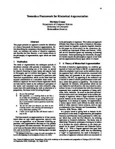
5. Implementation strategy illustration: Sobel edge detection The Sobel edge detection algorithm is one of the most commonly used techniques for edge detection [27]. It can be performed (approximately) by adding the absolute results of two separate convolutions (for horizontal and vertical edge strengths) as shown in Figure 8. In the following, we will present two possible FPGA implementations of the Sobel operation, both based on bit serial arithmetic. The first possible way of implementation is based on online arithmetic using Radix-2 Signed Digit number representation. This choice of arithmetic is motivated by the fact that an Absolute operation is needed after a convolution operation. This operation is naturally performed MSB first. Hence the choice of Most Significant Bit First arithmetic. Further, since a convolution is also involved, we need to use carry free arithmetic to be able to perform addition MSB first. Hence the choice of Signed Digit representation. The second implementation is based on two’s complement arithmetic LSBF for performing the two convolutions. Absolute operations will be performed in bit parallel using dedicated carry logic. A serial to parallel converter is hence needed. In both cases, the circuits are assembled by selecting the appropriate skeletons from the library. The corresponding FPGA configurations, with placement information, are generated automatically by the HIDE4k system. •
Online arithmetic based implementation
In this case, the Sobel circuit is assembled by selecting skeletons which use online arithmetic. For 8-bit input pixels, the minimum processing word length is 13 bits (because of the latency of the online adder). A floorplan of the resulting architecture for 256x256 image of 8-bits pixels on XC4036EX-2 (36x36 CLBs) is presented in Figure 9. The circuit occupies 475 CLBs. Timing simulation shows that the circuit can run at a speed of 75MHz which leads to a
9
theoretical frame rate of 88 frames per second. From experience, we note that a speed of 75MHz on XC4036EX-2 for this sort of operations is a very good figure. •
Two's complement LSBF based implementation
In this case, the Sobel circuit is assembled using skeletons which are implemented using 2's complement LSBF arithmetic. For 8-bit input pixels, the precision required in this case is only 11 bits. As stated above, in order to perform the ‘absolute’ operation in bit parallel, the two serial LSBF convolution outputs need first to be converted into bit parallel. The final addition is also performed in bit parallel. The latter is based on dedicated fast carry logic. A floorplan of the resulting architecture for 256x256 image of 8-bits pixels on XC4036EX-2 is presented in Figure 10. The circuit occupies 369 CLBs. This is more than 100 CLBs less than an online arithmetic based implementation. This is because of the reduced line buffer space since the required precision is just 11 bits (instead of 13 bits for an online based implementation). Timing simulation shows that the circuit can run at a speed of 75MHz which leads to a theoretical frame rate of 104 frames per second. Again, we note that such a speed is a very good figure on XC4036EX-2. Clearly, this solution is more efficient (in area and speed) than an online arithmetic based solution.
6. Summary In this paper, we have presented a framework for FPGA based Image Processing. Central to this framework is the Hardware Skeleton Library which contains a set of high level descriptions of task-specific architectures specifically optimised for Xilinx XC4000 FPGAs. The library also contains high level skeletons for compound operations, whose implementations include task-specific optimisations. Skeletons are parameterisable, and different skeletons for the same operation can be provided, for instance for different arithmetic representations. This gives the user a range of implementation choices. This in turn supports experimentation with different implementations and choosing the most suitable one for the particular constraints in hand (e.g. speed and area). We are investigating the possibility of doing some of this experimentation automatically, but for now we do it manually.
Given a complete algorithm description in terms of skeletons, an efficient
hardware configuration is generated automatically by our system. The paper shows that hardware skeletons are a promising approach to satisfy the dual requirement of achieving
10
very efficient hardware configurations while retaining the convenience and rapid development cycle of an application-oriented, high level programming model. Future directions include upgrading the system to handle other FPGA series (particularly Xilinx Virtex chips). The extension of the hardware skeleton library, both in supporting more arithmetic types and providing other skeletons for more sophisticated image processing operations (wavelet transform in particular), is being investigated. The automation of the process of selecting the appropriate implementation among different alternative solutions is also the subject of future work.
11
Input1 (e.g. image)
Input2 (e.g. image) image IP tasks
e.g.
Convolution
Convolution
+ Output (e.g. image, histogram etc.)
image
Figure 1. A hypothetical image processing algorithm modelled as a DAG graph
12
Int
Bit Serial SD, MSDF
Bit Serial 2’s complement, MSBF
Bit Parallel 2’s complement
Absolute value
Absolute value
Absolute value
Absolute value
Int
Bit Serial SD, MSDF (b)
Bit Serial 2’s complement, MSBF (c)
(a)
Bit Parallel 2’s complement (d)
Figure 2. A DAG node (a) with several possible implementations (b), (c) and (d)
13
Hardware Skeleton Library
Xilinx XC4000 FPGA
HIDE4k System
Bitstream DAG with logical data types
Solution generation
Optimisation
A DAG set of available implementations
Cost Based Analysis
A DAG set of optimised implementations
Code Generator
EDIF
DAG with specific data representation choices
Figure 3. Overall view of our implementation strategy
14
Xilinx PAR tools
To Image Processing Application Developer
High Level (compound) Skeletons library
Basic Image Operations Library (e.g. neighbourhood operations)
Arithmetic Cores Library
Figure 4. Hierarchical implementation of the Hardware Skeleton Library
15
Neighbourhood Operation
Local Op.
GlobalOp.
Convolution
*
Σ
Multiplicative maximum
*
Max
Multiplicative minimum
*
Min
Additive maximum
+
Max
Additive minimum
+
Min
Table 1. Image Algebra core operation set
16
Line Buffer1
Line BufferP-1
δLB
Processing Elements (PE)
δLB
Pixel Delays δ
δ
δ
δ
δ
δ
L
L
L
L
L
L
G
G
G
G
G
G
PE1
PEQ
PE Q*(P-2)+1
PE Q*(P-1) PE Q*(P-1)+1
PE Q*P
Figure 5. Architecture of a generic PxQ neighbourhood operation using P.Q Processing Elements (PEs)
17
Neighbourhood operation Nop-1
Neighbourhood operation Nop-2
Neighbourhood operation Nop-N
Figure 6. Parallel neighbourhood operations sharing the same input image
18
δCPE δCPE + δW A1,1
B1,1
L1
Compound Processing Element δW : Pixel delay (CPE)
Line BufferP-1
Line Buffer1 δCPE δCPE +δW A1,Q
L1
δCPE δCPE +δW AP-1,1
δCPE
δCPE δCPE +δW AP-1,Q
L1
L1
δCPE + δW AP,1
L1
δCPE δCPE + δW AP,Q
L1
G1
G1
G1
G1
G1
G1
δthru
δthru
δthru
δthru
δthru
δthru
L2 G2
CPE1
B1,Q
L2 G2
CPEQ
BP-1,1
BP-1,Q
L2 G2
L2
BP,1
G2
G2
CPEQ*(P-2)+1
CPEQ*(P-1)
L2
CPEQ*(P-1)+1
BP,Q
L2 G2
CPEQ*P
Figure 7. Architecture of a generic 2D, compound PxQ neighbourhood operation using P.Q Compound Processing Elements (CPEs)
19
convolution
convolution -1 -2 -1
~ ~ ~
-1 ~ 1
1 2 1
Absolute operation
-2 ~ 2
-1 ~ 1
Skeleton (see Figure 6)
Absolute operation
Absolute operation
Image-Image addition
Absolute operation
Image-Image addition
Figure 8. Sobel edge detection algorithm
20
Line Buffers
Absolute value unit
Input
Extra delay for data synchronisation Adder unit SDNR to binary converter
9 Compound Processing Elements
Output
Absolute value unit
Figure 9. Physical configuration of ‘Sobel’ on XC4036EX-2, using online arithmetic
21
Line Buffers
Serial to Parallel converter Parallel Absolute value Parallel Adder 9 Compound Processing Elements
Serial to Parallel converter
Parallel Absolute value
Figure 10. Physical configuration for ‘Sobel’ on XC4036EX-2, using 2’s complement LSBF
22
7. References [1]
Kean T, New B and Slous B, ‘A 800 MPixel/sec Reconfigurable Image Correlator on XC6216’, Proceedings of the 7th International Workshop on Field Programmable Logic and its Applications, FPL’ 97, pp 382-391.
[2]
Heron J, Trainor D, and Woods R, 'Implementation of the 2D DCT using a Xilinx XC6264 FPGA', IEEE Proceedings on the Workshop on Signal Processing systems, SiPS'97, IEEE Press, pp541-550.
[3]
Reza Ali M, Turney Robert D, ‘FPGA implementation of 2D wavelet transform’, Proceedings of the Asilomar Conference on Signals, Systems and Computers, Vol. 1, pp 584-588, 1999.
[4]
Synopsys Inc., ‘Behavioural Compiler’, Software documentation, 1998. http://www.synopsys.com/products/beh_syn/
[5]
C Level Design Inc, ‘C/C++ Synthesis System Compiler’, Product overview, 1998 http://www.cleveldesign.com/products/
[6]
The Embedded Solutions Limited, ‘Handel C information sheets’, 1999 http://www.embeddedsol.com
[7]
Scott Smith and David Black, ‘Pushing the Limits with Behavioral Compiler’, Synopsys Inc, 1999. http://www.synopsys.com/products/beh_syn/bc_compaq_wp.pdf
[8]
Zahir Jaffer and Bryan Piotto, ‘Experiences Using Behavioral Synthesis on an ATM Traffic & Queue Management ASIC’, Synopsys Inc, 1999 http://www.synopsys.com/products/beh_syn/bc_nortel_wp.pdf
[9]
Hutchings B, Bellows P, Hawkins J, Hemmert S, Nelson B and Rytting M, ‘A CAD suite for High-Performance FPGA design’, FCCM’99, Preliminary Proceedings.
[10] Benkrid K, ‘Design and Implementation of a High Level FPGA Based Coprocessor for Image and Video Processing’, PhD Thesis, Department of Computer Science, The Queen's University of Belfast, 2000. http://www.cs.qub.ac.uk/~K.Benkrid/MyThesis.html
[11] Cole M, ‘Algorithmic Skeletons: structured management of parallel computation’, MIT Press, 1989. [12] Darlington J, Ghanem M, and To H W, 'Structured Parallel Programming', In Programming Models for Massively Parallel Programming Computers, IEEE Computer Society Press, pp. 160-169, Sept 1993.
23
[13] Michaelson G J, Scaife N R, and Wallace A M, 'Prototyping parallel algorithms in Standard ML', Proceedings of British Vision Conference, Sep 1995. ftp://ftp.cee.hw.ac.uk/pub/funcprog/msw.bmvc95.ps.Z
[14] P. Dhaussy, J.-M. Filloque, B. Pottier, and S. Rubini. ArMen: an FPGA-based parallel architecture. In H.J. Siegel, editor, International Parallel Processing Symposium (Parallel System Fair), Cancùn, Mexico, April 1994. http://ubolib.univ-brest.fr/~armen/armen1-eng.html
[15] The ARDOISE project, “Architecture Reconfigurable Dynamiquement Orientée Image et Signal Embarquable”. http://www-etis.ensea.fr/Francais/AxesArchi/ai/dardoise/ardoise11.html
[16] Ritter G X, Wilson J N and Davidson J L, ‘Image Algebra: an overview’, Computer Vision, Graphics and Image Processing, No 49, pp 297-331, 1990. [17] Avizienis A, ‘Signed Digit Number Representation for Fast Parallel Arithmetic, IRE Transactions on Electronic Computer, Vol. 10, pp 389-400, 1961. [18] Moran J, Rios I and Meneses J, ‘Signed Digit Arithmetic on FPGAs’, More FPGAs, W Moore and W Luk (editors), Abington, EE&CS Books, pp 250, 1994. [19] Ercegovac M D, On-line arithmetic: an overview, SPIE Vol. 495, Real time signal processing VII, pp 86-93, 1984. [20] Crawford J D, ‘EDIF: A Mechanism for the Exchange of Design Information’, IEEE Design and Test of Computers, Vol. 2, No. 1, pp 63-69, 1984. [21] Crookes D, Alotaibi K, Bouridane A, Donachy P and Benkrid A, ‘An Environment for Generating FPGA Architectures for Image Algebra-based Algorithms’, ICIP98, Vol.3, pp. 990-994, 1998. [22] Benkrid K, Crookes D, Bouridane A, Corr P and Alotaibi K, ‘A High Level Software Environment for FPGA Based Image Processing’, Proc. IPA'99, IEE Seventh International Conference on Image Processing and its Applications, Manchester, pp. 112-116, 1999. [23] Xilinx Ltd, XC4000E and XC4000X Series Field Programmable Gate Arrays -Product Specification, 1999. http://www.xilinx.com/partinfo/4000.pdf
[24] Hwang K, ‘Computer Arithmetic Principles’, Architecture, and Design, Wiley, 1979. [25] Koren I, ‘Computer arithmetic algorithms’, Prentice-Hall, Inc, pp. 99-126, 1993. [26] Crookes D, Benkrid K, Bouridane A, Alotaibi K and Benkrid A, ‘Design and Implementation of a High Level Programming Environment for FPGA Based Image
24
Processing’, IEE proceedings: Vision, Image and Signal Processing, Vol. 147, No. 7, pp. 377-384. [27] Castleman K R, ‘Digital Image processing’, Prentice Hall, 1995, ISBN: 0132114674.
25